Transcription
TABLE OF CONTENTS1. GENERAL INFORMATION .31.1 PRODUCT DESCRIPTION FOR EQUIPMENT UNDER TEST (EUT) .31.2 TEST STANDARDS.31.3 OBJECTIVE .31.4 TEST METHODOLOGY .31.5 TEST FACILITY .32. SYSTEM TEST CONFIGURATION .32.1 JUSTIFICATION .32.2 EUT EXERCISE SOFTWARE .32.3 EQUIPMENT MODIFICATIONS .32.4 LIST OF MEASURING EQUIPMENTS USED .33. SUMMARY OF TEST RESULTS.34. ETSI EN 300 330-2 V1.1.1 (2001- 06)§4.1.1 – RADIATED FIELD STRENGTH OR POWER.34.1 STANDARD APPLICABLE .34.2 METHODS OF MEASUREMENT .34.3 BASIC TEST SETUP BLOCK DIAGRAM .34.4 TEST RESULT.35. ETSI EN 300 330-2 V1.1.1 (2001- 06)§4.1.2 – PERMITTED FREQUENCY RANGE OF THEMODULATION BANDWIDTH.35.1 STANDARD APPLICATION .35.2 LIMIT OF PERMITTED FREQUENCY RANGE OF THE MODULATION BANDWIDTH .35.3 METHODS OF MEASUREMENT .35.4 TEST RESULT.36. ETSI EN 300 330-2 V1.1.1 (2001- 06)§4.1.2A – SPURIOUS EMISSIONS .36.1 STANDARD APPLICATION .36.2 LIMIT OF SPURIOUS EMISSIONS .36.2.1 LIMIT OF RADIATED FIELD STRENGTH .36.2.2 LIMIT OF EFFECTIVE RADIATED POWER .36.3 METHODS OF MEASUREMENT .36.3.1 METHODS OF MEASUREMENT OF RADIATED FIELD STRENGTH ( 30 MHZ) .36.3.2 METHODS OF MEASUREMENT OF EFFECTIVE RADIATED POWER ( 30 MHZ).36.4 TEST RESULT.37. ETSI EN 300 330-2 V1.1.1 (2001- 06)§4.1.3 – DUTY CYCLE .37.1 STANDARD APPLICATION .37.2 DEFINITION.37.3 DUTY CYCLE CLASSES .37.4 TEST RESULT.38. ETSI EN 300 330-2 V1.1.1 (2001- 06)§4.2 – RECEIVER REQUIREMENTS.38.1 STANDARD APPLICATION .38.2 LIMIT OF SPURIOUS EMISSIONS .38.2.1 LIMIT OF RADIATED FIELD STRENGTH .38.2.2 LIMIT OF EFFECTIVE RADIATED POWER .38.3 METHODS OF MEASUREMENT .38.3.1 METHODS OF MEASUREMENT OF RADIATED FIELD STRENGTH ( 30 MHZ) .38.3.2 METHODS OF MEASUREMENT OF EFFECTIVE RADIATED POWER ( 30 MHZ).3ANNEX A: H-FIELD MEASUREMENTS AND LIMITS AT 3 M .3ANNEX B: EUT-SETUP PHOTO .3Report No.: BCT10FR-0853E-1Page 2 of 21
1. GENERAL INFORMATION1.1 Product Description for Equipment Under Test (EUT)Client InformationApplicant:Address of applicant:FINGERTEC WORLDWIDE SDN BHDNO.6, 8 & 10, JALAN BK 3/2, BANDAR KINRARA, 47100PUCHONG, SELANGOR, MALAYSIAManufacturer:Address of manufacturer:FINGERTEC WORLDWIDE LIMITEDPeking University Founder Shiyan Science Park, Bao’an, Shenzhen,China. 518108General Description of E.U.TItemsDescriptionEUT Description:RFID Access ControlModel No.:KadexTrademark:FINGERTECRF Output Power:26.82dBμA/mTransmit Frequency:125.2KHzNumber of Channels:1Emission designation:3K9N0NDuty cycle:100%Antenna Type:Built-in AntennaRated Voltage:DC 12V 1.5 AAdapter specification:Product name: AC ADAPTOR3 metersTrade Mark:KtecModel:KSAD1200 150W1UV-1Input:100-240V 50/60Hz 0.4AOutput: DC 12VClassification of Equipment:1.5AThe Transmitter is a narrow-band and without voice application.The Transmitter is ranged into Category I.* The test data gathered are from the production sample provided by the manufacturer.Category of EquipmentCategory IGeneralCategory IIPortable EquipmentCategory IIIEquipment for normal indoor useReport No.: BCT10FR-0853E-1Page 3 of 21
1.2 Test StandardsThe following Declaration of Conformity report of EUT is prepared in accordance withETSI EN 300 330-1V1.4.1 (2004-11)ETSI EN 300 330-2 V1.1.1 (2001-06)1.3 ObjectiveThe following Declaration of Conformity report of an ITE device is in accordance with ETSI EN300 330-1 V1.4.1 (2004-11), Electromagnetic compatibility and Radio spectrum Matters (ERM);Short Range Devices(SRD); Radio equipment in the frequency range 9KHz to 25 MHz andinductive loop systems in the frequency range 9KHz to 30MHz;and ETSI EN 300 330-2 V1.1.1(2001-06), Electromagnetic compatibility and Radio spectrum Matters (ERM); Short RangeDevices(SRD); Radio equipment in the frequency range 9KHz to 25 MHz and inductive loopsystems in the frequency range 9KHz to 30MHz; Part 2: Harmonized EN under article 3.2 of theR&TTE Directive.1.4 Test MethodologyAll measurement required was performed at laboratory of Bontek Compliance Testing LaboratoryLtd at 1/F, Block East H-3, OCT Eastern Ind. Zone, Qiaocheng East Road, Nanshan, Shenzhen,China1.5 Test FacilityThe test facility is recognized, certified, or accredited by the following organizations:FCC – Registration No.: 338263Bontek Compliance Testing Laboratory Ltd EMC Laboratory has been registered and fullydescribed in a report filed with the (FCC) Federal Communications Commission. The acceptanceletter from the FCC is maintained in our files. Registration 338263, March 24, 2008.IC Registration No.: 7631AThe 3m alternate test site of Bontek Compliance Testing Laboratory Ltd EMC Laboratory hasbeen registered by Certification and Engineer Bureau of Industry Canada for the performance ofwith Registration NO.: 7631A on August 2009.TUV - Registration No.: UA 50145371-0001Shenzhen Bontek Electronic Technology Co.,Ltd An assessment of the laboratory wasconducted according to the"Procedures and Conditions for EMC Test Laboratories"with referenceto EN ISO/IEC 17025 by a TUV Rheinland auditor. Audit Report NO. 17010783-001CNAS - Registration No.: L3923Bontek Compliance Testing Laboratory Ltd has been accredited by China National AccreditationService for Conformity Assessment (CNAS) for the competence in the field of EMC and Safetytesting with the Registration No.: L3923 on February, 2009.Report No.: BCT10FR-0853E-1Page 4 of 21
2. SYSTEM TEST CONFIGURATION2.1 JustificationThe system was configured for testing in a typical fashion (as normally used by a typical user).2.2 EUT Exercise SoftwareThe EUT exercising program used during radiated and conducted testing was designed toexercise the various system components in a manner similar to a typical use. The softwareoffered by BCT can exercise the EUT as data transferring between the EUT and the host.2.3 Equipment ModificationsBCT has not done any modification on the EUT.2.4 List of Measuring Equipments UsedItemsEquipmentManufacturerModel No.Last CalCalibrationPeriod1EMI Test ReceiverR&SESI 262010/61 year2Horn AntennaR/SCH14-H0522010/61 year33m Semi- AnechoicChamberETSN/A2010/61 year4Horn AntennaR/SHF9062010/61 year5Spectrum AnalyzerHP8594EM2010/61 yearLoop AntennaFor other test: Bontek Compliance Testing Laboratory LtdItemsEquipmentManufacturerModel No.Serial No.Last CalCalibrationPeriod1EMI Test ReceiverR&SESCI1006872010/61 Year2EMI Test ReceiverR&SESPI72010/61 Year3AmplifierHP8447D1000971937A024922010/61 Year43 phase ArtificialMains(L.I.S.N)SCHWARZBECKNSLK 812881282472010/61 Year5TRILOGBroadband TestAntennaSCHWARZBECKVULB91639163-3242010/61 Year6Horn AntennaSCHWARZBECKBBHA9120AD692502010/61 Year7High Field BiconicalAntennaELECTROMETRICSEM-69131662010/61 Year8Log PeriodicAntennaELECTROMETRICSEM-69508112010/61 Year9Remote ActiveVertical AntennaELECTROMETRICSEM-68923042010/61 Year10Power ClampSCHWARZBECKMDS-2138122010/61 Year11Temperature &Humidity ChamberTOPSTATTOS-831A3438A052082010/61 yearReport No.: BCT10FR-0853E-1Page 5 of 21
3. SUMMARY OF TEST RESULTSResults reported relate only to the product tested.ETSI EN 300 330-2V1.3.1Section 4.1.1Section 4.1.2Description of TestRadiated field strengthor powerPermitted range ofoperating frequenciesLimitResultsRadiated H-field 64.5 dBμA/mRadiated E-fieldnot applicableRF Carrierr currentnot applicableSee Section 7.3.3Conducted spuriousemissionnot applicableRadiated spuriousemissionSee Section 7.4.3.2table 6 And Section7.4.4.2 table 7PassPassSection 4.1.2aSpurious emissionsPassSection 4.1.3Duty cycleSee Section 7.5.3 table 8PassSection 4.2.3Receiver spuriousradiationsSee Section 8.3.3 table 11N/ATable 2: test summaryReport No.: BCT10FR-0853E-1Page 6 of 21
4. ETSI EN 300 330-2 V1.1.1 (2001- 06)§4.1.1 – Radiated Field Strength orPower4.1 Standard ApplicableThe limits presented in the present document are the required field strengths to allow satisfactoryoperation of inductive systems. These levels were determined after careful analysis within ETSIand ERC/ECC/CEPT.Maximum H-field strength under normal and extreme conditions is given in table 3.Exceptionally, some administrations may have a need to provide additional protection to someexisting services operating on frequencies covered by table 3.In all cases SRDs operate on a non-interference basis. Solutions can range from site engineeringto field strength modification and can be used on a case by case basis.Additional information is available in CEPT/ERC Recommendation 70-03 [3] and whereapplicable ERC or ECC Decisions.Warning: The limit be given in below test data and table 2 is at 3 m ,is convertedvalue( see Annex A ).Report No.: BCT10FR-0853E-1Page 7 of 21
4.2 Methods of MeasurementThe measurements of the transmitter radiated H-field shall be made on an open field test site asspecified in clause A.1.3. Any measured values shall be at least 6 dB above the ambient noiselevel.The H-field produced by the equipment shall be measured at standard distance of 10 m.Where this is not practical,e.g. due to physical size of the equipment including the antenna orwith use of special field cancelling antenna, then other distances may be used. When anotherdistance is used, the distance used and the field strength value measured shall be stated in thetest report. In this case, the measured value at actual test distance shall be extrapolated to 10 maccording to annex J and these calculations shall be stated in the test report.The H-field is measured with a shielded loop antenna connected to a measurement receiver. Themeasuring bandwidth and detector type of the measurement receiver shall be in accordance withclause 6.6.The equipment under test shall operate where possible, with modulation. Where this is notpossible, it shall be stated in the test report.For transmitters using a continuous wideband swept carrier, the measurement shall be made withthe sweep off. When itis not possible to turn the sweep off the measurements shall be made withthe sweep on and this shall be stated in the test report.For measuring equipment calibrated in dBμV, the reading should be reduced by 51,5 dB to beconverted to dBμA/m.Report No.: BCT10FR-0853E-1Page 8 of 21
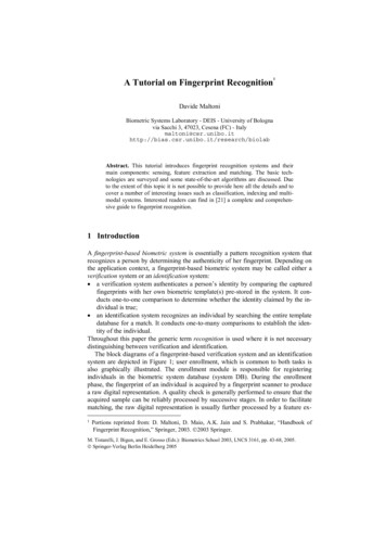
4.3 Basic Test Setup Block Diagram4.4 Test ResultTemperature ( ) : 22 23EUT: RFID Access ControlHumidity (%RH ): 50 54M/N: KadexBarometric Pressure ( mbar ): 950 1000Operation Condition: continue transmitting ModeIndicatedFrequencyAmpl./ PolarH/VTest 5H25.9264.538.58Note: The limit in above table is at 3 m measurement distance,and comply with table 3 note 1.Report No.: BCT10FR-0853E-1Page 9 of 21
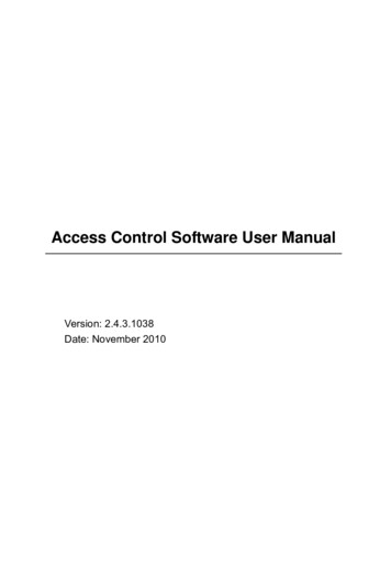
Antenna horizontalAntenna verticalReport No.: BCT10FR-0853E-1Page 10 of 21
5. ETSI EN 300 330-2 V1.1.1 (2001- 06)§4.1.2 – Permitted FrequencyRange of The Modulation Bandwidth5.1 Standard ApplicationAccording to ETSI EN 300 330-1 V1.4.1, This clause refers to clause 7.3.5.2 Limit of Permitted Frequency Range of The Modulation BandwidthThe permitted range of the modulation bandwidth shall be within the limits of the assignedfrequency band stated in CEPT/ERC Recommendation 70-03 [3] or ERC/ECC/CEPT Decisions.5.3 Methods of MeasurementThe transmitter shall be connected to an artificial antenna or if the transmitter has an integralantenna a test fixture shall be used (see clause 6.3). The RF output of the equipment shall beconnected to a spectrum analyser via a 50 Ω variable attenuator.The transmitter shall be operated at the nominal carrier power or field strength measured undernormal test conditions in clause 7.2. The attenuator shall be adjusted to an appropriate leveldisplayed at the spectrum analyser screen.The transmitter shall be modulated with standard test modulation (see clauses 6.1.1 and 6.1.2). Ifthe equipment cannot be modulated externally, the internal modulation shall be used.The output of the transmitter, with or without test fixture, shall be measured by using a spectrumanalyser with a resolution bandwidth appropriate to accept all major side bands.The power levelcalibration of the spectrum analyser shall then be related to the power level or field strengthmeasured in clause 7.2. The calculation will be used to calculate the absolute level of thesideband power.The frequencies of the upper and lower points, where the displayed power envelope of themodulation including frequency drift is equal to the appropriate level defined in clause 7.3.1 isrecorded as the modulation bandwidth.The measurements shall be made during normal and extreme test conditions (clauses 5.4.1 and5.4.2 applied simultaneously).5.4 Test ResultTemperature ( ) : 22 23EUT: RFID Access ControlHumidity (%RH ): 50 54M/N: KadexBarometric Pressure ( mbar ): 950 1000Operation Condition: continue transmitting ModeTest ConditionsFrequency (KHz)at -30dBm / 100KHz (eirp)fLfHTnor 20 C125.245125.252Tmin -20 C125.256125.261Tmax 55 C125.259125.273Report No.: BCT10FR-0853E-1Page 11 of 21
6. ETSI EN 300 330-2 V1.1.1 (2001- 06)§4.1.2a – Spurious emissions6.1 Standard ApplicationAccording to ETSI EN 300 330-1 V1.4.1, This clause refers to clause 7.4.6.2 Limit of Spurious Emissions6.2.1 Limit of Radiated Field StrengthRadiated emissions below 30 MHz shall not exceed the generated H-field dBμA/m at 10 m givenin below table.Note:The limit be given in below test data is at 3 m ,is converted value( see Annex A ).6.2.2 Limit of Effective Radiated PowerNote:The limit be given in below test data is at 3 m ,is converted value( see Annex A ).6.3 Methods of measurement6.3.1 Methods of measurement of Radiated Field Strength ( 30 MHz)The field strength shall be measured for frequencies below 30 MHz. The equipment under testshall be measured at a distance of 10 m on an outdoor test site. The test antenna shall be acalibrated shielded magnetic field antenna. The equipment under test and test antenna shall bearranged as stated in clause A.1.The equipment under test shall be switched on with normal modulation. The characteristics of themodulation signal used shall be stated on the test report. The measuring receiver shall be tunedover the frequency range 9 kHz to 30 MHz, except for the frequency band on which thetransmitter is intended to operate.At each frequency at which a relevant spurious signal is detected the equipment under test andthe test antenna shall be rotated until maximum field strength is indicated on the measuringreceiver. This level shall be noted.If the transmitter can be operated in the standby mode, then the measurements shall be repeatedin the standby mode.For measuring equipment calibrated in dBμV, the reading should be reduced by 51,5 dB to beconverted to dBμA/m.Report No.: BCT10FR-0853E-1Page 12 of 21
6.3.2 Methods of Measurement of Effective Radiated Power ( 30 MHz)The equipment shall be placed at the specified height on a non-conducting support and in theposition closest to normal use as declared by the provider.The test antenna shall be oriented for vertical polarization. The output of the test antenna shall beconnected to a measuring receiver.The transmitter shall be switched on with normal modulation, and the measuring receiver shall betuned over the frequency range 30 MHz to 1 000 MHz.At each frequency at which a relevant spurious component is detected, the test antenna shall beraised and lowered through the specified range of heights until a maximum signal level isdetected on the measuring receiver.The transmitter shall then be rotated through 360 in the horizontal plane, until the maximumsignal level is detected by the measuring receiver. The maximum signal level detected by themeasuring receiver shall be noted.The substitution antenna shall be oriented for vertical polarization and calibrated for thefrequency of the spurious component detected.The frequency of the calibrated signal generator shall be set to the frequency of the spuriouscomponent detected. The input attenuator setting of the measuring receiver shall be adjusted inorder to increase the sensitivity of the measuring receiver, if necessary.The test antenna shall be raised and lowered through the specified range of heights to ensurethat the maximum signal is received. When a test site according to clause A.1 is used, there is noneed to vary the height of the antenna.The input signal to the substitution antenna shall be adjusted until an equal or a known relatedlevel to that detected from the transmitter is obtained on the measuring receiver. The input signalto the substitution antenna shall be recorded as a power level and corrected for any change ofinput attenuator setting of the measuring receiver.The measure of the effective radiated power of the spurious components is the larger of the twopower levels recorded for each spurious component at the input to the substitution antenna,corrected for the gain of the substitution antenna if necessary.If an unmodulated carrier cannot be obtained then the measurements shall be made with thetransmitter modulated by the normal test signal (see clause 6.1.2) in which case this fact shall berecorded in the test report.If standby mode is available, the measurements shall be repeated in that mode.6.4 Test ResultTemperature ( ) : 22 23EUT: RFID Access ControlHumidity (%RH ): 50 54M/N: KadexBarometric Pressure ( mbar ): 950 1000Operation Condition: continue transmitting ModeReport No.: BCT10FR-0853E-1Page 13 of 21
egreeSubstitutedTest tdBuA/mMargindBbelow 30MHzTx mode0.25131.21001.50H0.251-2 uV/mTableAngleDegreeStand byH0.232-------SubstitutedTest e 30MHzTx 842.94Stand 1.4981.056.561001.46Report No.: BCT10FR-0853E-1V81.05Page 14 of 21
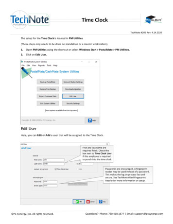
7. ETSI EN 300 330-2 V1.1.1 (2001- 06)§4.1.3 – Duty Cycle7.1 Standard ApplicationAccording to ETSI EN 300 330-1 V1.4.1, This clause refers to clause 7.5;7.2 DefinitionFor the purpose of the present document the term duty cycle refers to the ratio of the total ontime of the "message" during any one hour relative to one hour period. The device may betriggered either automatically or manually and depending on how the device is triggered will alsodepend on whether the duty cycle is fixed or random.7.3 Duty Cycle ClassesIn a period of 1 hour the duty cycle shall not exceed the values given in below table.7.4 Test ResultTemperature ( ) : 22 23EUT: RFID Access ControlHumidity (%RH ): 50 54M/N: KadexBarometric Pressure ( mbar ): 950 1000Operation Condition: continue transmitting ModeTest plots see following pagesThe Duty Cycle 1 100%Report No.: BCT10FR-0853E-1Page 15 of 21
Report No.: BCT10FR-0853E-1Page 16 of 21
8. ETSI EN 300 330-2 V1.1.1 (2001- 06)§4.2 – Receiver Requirements8.1 Standard ApplicationThe adjacent channel selectivity in-band, as defined in EN 300 330-1 [2], clause 8.1.1, shall notbe less than the limits in EN 300 330-1 [2], clause 8.1.3, table 10.8.2 Limit of Spurious Emissions8.2.1 Limit of Radiated Field StrengthRadiated emissions below 30 MHz shall not exceed the generated H-field dBμA/m at 10 m givenin below table.8.2.2 Limit of Effective Radiated PowerThe measured values shall not exceed 2 nW.Report No.: BCT10FR-0853E-1Page 17 of 21
8.3 Methods of measurement8.3.1 Methods of measurement of Radiated Field Strength ( 30 MHz)The field strength shall be measured for frequencies below 30 MHz. The equipment under testshall be measured at a distance of 10 m on an outdoor test site. The test antenna shall be acalibrated shielded magnetic field antenna. The equipment under test and test antenna shall bearranged as stated in clause A.1.The equipment under test shall be switched on with normal modulation. The characteristics of themodulation signal used shall be stated on the test report. The measuring receiver shall be tunedover the frequency range 9 kHz to 30 MHz, except for the frequency band on which thetransmitter is intended to operate.At each frequency at which a relevant spurious signal is detected the equipment under test andthe test antenna shall be rotated until maximum field strength is indicated on the measuringreceiver. This level shall be noted.If the transmitter can be operated in the standby mode, then the measurements shall be repeatedin the standby mode.For measuring equipment calibrated in dBμV, the reading should be reduced by 51,5 dB to beconverted to dBμA/m.8.3.2 Methods of Measurement of Effective Radiated Power ( 30 MHz)The equipment shall be placed at the specified height on a non-conducting support and in theposition closest to normal use as declared by the provider.The test antenna shall be oriented for vertical polarization. The output of the test antenna shall beconnected to a measuring receiver.The transmitter shall be switched on with normal modulation, and the measuring receiver shall betuned over the frequency range 30 MHz to 1 000 MHz.At each frequency at which a relevant spurious component is detected, the test antenna shall beraised and lowered through the specified range of heights until a maximum signal level isdetected on the measuring receiver.The transmitter shall then be rotated through 360 in the horizontal plane, until the maximumsignal level is detected by the measuring receiver.The maximum signal level detected by themeasuring receiver shall be noted.The substitution antenna shall be oriented for vertical polarization and calibrated for thefrequency of the spurious component detected.The frequency of the calibrated signal generator shall be set to the frequency of the spuriouscomponent detected. The input attenuator setting of the measuring receiver shall be adjusted inorder to increase the sensitivity of the measuring receiver, if necessary.The test antenna shall be raised and lowered through the specified range of heights to ensurethat the maximum signal is received.When a test site according to clause A.1 is used, there is noReport No.: BCT10FR-0853E-1Page 18 of 21
need to vary the height of the antenna.The input signal to the substitution antenna shall be adjusted until an equal or a known relatedlevel to that detected from the transmitter is obtained on the measuring receiver. The input signalto the substitution antenna shall be recorded as a power level and corrected for any change ofinput attenuator setting of the measuring receiver.The measure of the effective radiated power of the spurious components is the larger of the twopower levels recorded for each spurious component at the input to the substitution antenna,corrected for the gain of the substitution antenna if necessary.If an unmodulated carrier cannot be obtained then the measurements shall be made with thetransmitter modulated by the normal test signal (see clause 6.1.2) in which case this fact shall berecorded in the test report.Note: The EUT have not clarify receiver ,so this test is not applicableReport No.: BCT10FR-0853E-1Page 19 of 21
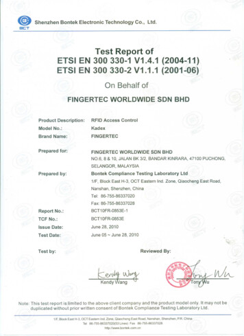
Annex A: H-field measurements and limits at 3 mThe H-field limit in dBμA/m at 3 m, H3m, is determined by the following equation:H3m H10m C3where:H10m is the H-field limit in dBμA/m at 10m distance according to the present document; andC3 is a conversion factor in dB determined from figure A.Correction factor, C3, for limits at 3 m distance, dBFrequency , MHzFigure A: Conversion factor C3 versus frequencyReport No.: BCT10FR-0853E-1Page 20 of 21
Annex B: EUT-Setup photoReport No.: BCT10FR-0853E-1Page 21 of 21
2. SYSTEM TEST CONFIGURATION 2.1 Justification The system was configured for testing in a typical fashion (as normally used by a typical user). 2.2 EUT Exercise Software The EUT exercising program used during radiated and conducted testing was designed to exercise the various system components in a manner similar to a typical use. The software