Transcription
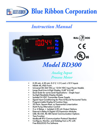
Blue Ribbon CorporationInstruction ManualModel BD300Analog InputProcess Meter 0-20 mA, 4-20 mA, 0-5 V, 1-5 V, and 10 V InputsNEMA 4X, IP65 FrontUniversal 85-265 VAC,or 12/24 VDC Input Power ModelsLarge Dual-Line 6-Digit Display, 0.60” & 0.46”Dual-Scale for some Level Applications – Single InputSunlight Readable Display ModelsIsolated 24 VDC Transmitter Power SupplySignal Input Conditioning for Flow & Round Horizontal TanksProgrammable Display & Function Keys32-Point, Square Root, or Exponential LinearizationMulti-Pump Alternation Control2 or 4 Relays Isolated 4-20 mA Output OptionsExternal 4-Relay & Digital I/O Expansion ModulesUSB, RS-232, RS-485 Serial Communication OptionsTare FunctionModbus RTU Communication Protocol StandardConfigure, Monitor, and Datalog from a PC withFree BULLDOG Pro Software
Model BD300 Analog Input Process MeterInstruction ManualDISCLAIMER: The information contained in this document is subject to change without notice. Blue Ribbon Corp. makes no representationsor warranties with respect to the contents herein and specifically disclaims any implied warranties of merchantability orfitness for a particular purpose.CAUTION: Read completeinstructions prior to installationand operation of the meter.WARNING!WARNING: Risk ofelectric shock orpersonal injury.This product is not recommended for life supportapplications or applications where malfunctioningcould result in personal injury or property loss.Anyone using this product for such applications doesso at his/her own risk. Blue Ribbon Corporationshall not be held liable for damages resulting fromsuch improper use.Limited WarrantyBlue Ribbon Corporation warrants this product against defects in material orworkmanship for the specified period under “Specifications” from the date ofshipment from the factory. Blue Ribbon’s liability under this limited warranty shallnot exceed the purchase value, repair, or replacement of the defective unit.Registered TrademarksAll trademarks mentioned in this document are the property of their respectiveowners. 2011-2012 Blue Ribbon Corporation. All rights reserved.www.blueribboncorp.com2
Table of Contents1. Introduction . . . . . . . . . . . . . . . . . . . . 12. Ordering Information. . . . . . . . . . . . . . . . 23. Specifications . . . . . . . . . . . . . . . . . . . . . 43.1.General. . . . . . . . . . . . . . . . . . . . . . . . . . . . . . . . . . . . . 43.2.Process Input. . . . . . . . . . . . . . . . . . . . . . . . . . . . . . . . . 63.3.Relays. . . . . . . . . . . . . . . . . . . . . . . . . . . . . . . . . . . . . . 73.4.Isolated 4-20 mA Transmitter Output. . . . . . . . . . . . . . 83.5.ModBUS RTU Serial Communications. . . . . . . . . . . . . 83.6.COMPLIANCE INFORMATION. . . . . . . . . . . . . . . . . . . . 93.7.Electromagnetic Compatibility. . . . . . . . . . . . . . . . . . . . 94. Safety Information . . . . . . . . . . . . . . . . . 105. Installation . . . . . . . . . . . . . . . . . . . . . 105.1.Unpacking. . . . . . . . . . . . . . . . . . . . . . . . . . . . . . . . . . 105.2.Panel Mounting Instructions. . . . . . . . . . . . . . . . . . . . 115.3.Configuration for 12 or 24 VDC Power Option. . . . . . 135.4.Transmitter Supply Voltage Selection (P , P-). . . . . . 145.5.Connections. . . . . . . . . . . . . . . . . . . . . . . . . . . . . . . . . 14Model BD300 Analog Input Process Meter - Instruction Manual
6. Setup And Programming . . . . . . . . . . . . . . 226.1.Front Panel Buttons and Status LED Indicators. . . . . . 236.2.Display Functions & Messages. . . . . . . . . . . . . . . . . . 246.3.Main Menu. . . . . . . . . . . . . . . . . . . . . . . . . . . . . . . . . 286.4.Setting Numeric Values. . . . . . . . . . . . . . . . . . . . . . . . 296.5.Setting Up the Meter (SEtuP). . . . . . . . . . . . . . . . . . . 306.6.Setting the Relay Operation (rELAy). . . . . . . . . . . . . . 416.7.Relay and Alarm Operation Diagrams. . . . . . . . . . . . 446.8.Relay Operation Details. . . . . . . . . . . . . . . . . . . . . . . 526.9.Scaling the 4-20 mA Analog Output (Aout). . . . . . . . 626.10. Reset Menu (rESEt). . . . . . . . . . . . . . . . . . . . . . . . . . . 636.11. Control Menu (Contrl). . . . . . . . . . . . . . . . . . . . . . . . 636.12. Setting Up the Password (PASS). . . . . . . . . . . . . . . . . 646.13. Advanced Features Menu. . . . . . . . . . . . . . . . . . . . . . 667. Meter Operation . . . . . . . . . . . . . . . . . . 837.1.Front Panel Buttons Operation. . . . . . . . . . . . . . . . . . 837.2.Function Keys Operation. . . . . . . . . . . . . . . . . . . . . . . 847.3.F4 Operation. . . . . . . . . . . . . . . . . . . . . . . . . . . . . . . . 847.4.Maximum/Minimum Readings. . . . . . . . . . . . . . . . . . 848. Troubleshooting . . . . . . . . . . . . . . . . . . 858.1.Diagnostics Menu (d iAG). . . . . . . . . . . . . . . . . . . . . . 858.2.Reset Meter to Factory Defaults. . . . . . . . . . . . . . . . . . 868.3.Troubleshooting Tips. . . . . . . . . . . . . . . . . . . . . . . . . . 918.4.Alphabetical List of Display Functions & Messages. . 929. How To Contact Blue Ribbon . . . . . . . . . . 101Model BD300 Analog Input Process Meter - Instruction Manual
Table of FiguresFigure 1. 1/8 DIN Panel Cutout Dimensions. 11Figure 2. Panel Mounting Details. 11Figure 3. Meter Dimensions - Side View. 12Figure 4. Meter Dimensions - Top View. 12Figure 5. Jumper Configuration for 12/24 VDC Power. 13Figure 6. Transmitter Supply Voltage Selection. 14Figure 7. Connector Labeling for Fully Loaded BD300. 15Figure 8. Power Connections. 15Figure 9. Transmitters Powered by Internal Supply. 16Figure 10. Transmitter Powered by Ext. Supply or Self-Powered. 16Figure 11. Voltage Input Connections. 17Figure 12. Relay Connections. 17Figure 13. AC and DC Loads Protection. 18Figure 14. Low Voltage DC Loads Protection. 18Figure 15. F4 Digital Input Connections. 19Figure 16. 4-20 mA Output Connections. 19Figure 17. Expansion Modules & DIN Rail Mounting Kit. 20Figure 18. External Relays Module Connections. 21Figure 19. Digital I/O Module Connections. 21Figure 20. Interlock Connections. 21Figure 21. Acknowledge Relays w/Function Key or Digital Input. 57Figure 22. 1/8 DIN Panel Cutout Template. 97Model BD300 Analog Input Process Meter - Instruction Manual
Return to Table of ContentsModel BD300 Analog Input Process MeterInstruction ManualDISCLAIMER: The information contained in this document is subject to change without notice.Blue Ribbon Corp. makes no representations or warranties with respect to the contents herein and specifically disclaims any implied warranties of merchantability orfitness for a particular purpose.1. IntroductionThe BULLDOG BD300 is a multi-purpose, easy to use digital process meter ideal forlevel, flow rate, temperature, or pressure transmitter applications. It accepts currentand voltage signals (e.g. 4-20 mA, 0-10 V). Three of the front panel buttons can becustom-programmed for a specific operation. The analog input can be scaled todisplay the process in two different scales; for example the main display could indicatelevel in feet and the second display could indicate the volume in gallons.The basic model includes an isolated 24 VDC transmitter power supply that can beused to power the input transmitter or other devices. An additional isolated 24 VDCpower supply is included with the 4-20 mA output option. A digital input is standard.A fully loaded BD300 meter has the following: four SPDT relays, 4-20 mA output, and two24 VDC power supplies. The BD300 capabilities may be enhanced by adding thefollowing external expansion modules: four SPST relays (creating an eight-relay processmeter), two digital I/O modules with four inputs and four outputs each, and USB, RS-232or RS-485 communication adapters.The eight relays can be used for alarm indication or process control applications, such aspump alternation control. The 4-20 mA isolated output, Modbus RTU serialcommunications, and digital I/O options make the BD300 an excellent addition to anysystem.1
Return to Table of ContentsModel BD300 Analog Input Process MeterInstruction Manual2. Ordering Information2.1.Standard Models85-265 VAC Model2.2.12/24 VDCOptions InstalledBD300-10BD300-20No OptionsBD300-12BD300-222 RelaysBD300-11BD300-214-20 mA OutputBD300-14BD300-244 RelaysBD300-13BD300-232 Relays & 4-20 mA OutputBD300-15BD300-254 Relays & 4-20 mA OutputSunBright Display Models85-265 VAC Model12/24 VDCOptions InstalledBD300-10XBD300-20XNo OptionsBD300-12XBD300-22X2 RelaysBD300-11XBD300-21X4-2 mA OutputBD300-14XBD300-24X4 RelaysBD300-13XBD300-23X2 Relays & 4-20mA OutputBD300-15XBD300-25X4 Relays & 4-20mA Output2
Return to Table of ContentsModel BD300 Analog Input Process Meter2.3.Instruction ManualAccessoriesModelDescriptionBDRMKDIN rail mounting kit for two expansion modulesBDXM4 SPST (Form A) relaysBDIO4 Digital inputs & 4 digital outputs (2 may be connected)BDCCCMeter copy cableBD232SARS-232 serial adapterBD422SARS-485 serial adapterBDI232-422/485RS-232 to RS-422/485 isolated converterBDN232-422/485RS-232 to RS-422/485 non-isolated converterBDUSBSAUSB serial adapterBDNUSB-232USB to RS-232 non-isolated converterBDIUSB-422/485USB to RS-422/485 isolated converterBDNUSB-422/485USB to RS-422/485 non-isolated converterBD6901Suppressor (snubber): 0.01 µF/470 Ω, 250 VAC2.4.EnclosuresModelDescriptionBD2811 Meter Plastic NEMA 4X EnclosureBD2822 Meter Plastic NEMA 4X Enclosure3
Return to Table of ContentsModel BD300 Analog Input Process MeterInstruction Manual3. SpecificationsExcept where noted, all specifications apply to operation at 25 C ( 77 F).3.1.GeneralDISPLAYDISPLAY INTENSITYDISPLAY UPDATE RATEOVERRANGEUNDERRANGEDISPLAY ASSIGNMENTMain display: 0.60” (15mm) high, red LEDsSecond display: 0.46” (12mm) high, red LEDs6 digits each (-99999 to 999999), with lead zero blankingEight user selectable intensity levels5/second (200 ms)Display flashes 999999Display flashes -99999The main (Big) and small (Little) displays may be assigned to PV1, PV2, PCT, dr4-u, d gross, d-nt-g, max/min max & min, set points, units (small display only, orModbus input.PROGRAMMING METHODS Four front panel buttons, digital inputs, PC and BULLDOG Pro software, Modbusregisters, or cloning using Copy function.NOISE FILTERFILTER BYPASSRECALIBRATIONProgrammable from 2 to 199 (0 will disable filter)MAX/MINDISPLAYPASSWORDMax/Min readings reached by the process are stored until reset by the user or untilpower to the meter is turned off.POWER OPTIONS85-265 VAC 50/60 Hz, 90-625 VDC, 20 W max or jumper selectable 12/24 VDC 10%, 15 W maxISOLATED TRANSMITTERPOWER SUPPLYTerminals P & P-: 24 VDC 10%. 12/24 VDC powered models selectable for24, 10, or 5 VDC supply (internal jumper J4). 85-265 VAC models rated @ 200mA max, 12/24 VDC powered models rated @ 100 mA max, @ 50 mA max for 5or 10 VDC supply.NON-VOLATILE MEMORYAll programmed settings are stored in non-volatile memory for a minimum of tenyears if power is lost.FUSERequired external fuse: UL Recognized, 5 A max, slow blow; up to 6 meters mayshare one 5 A fuseProgrammable from 0.1 to 99.9% of calibrated spanAll ranges are calibrated at the factory. Recalibration is recommended at least every12 months.Three programmable passwords restrict modification of programmed settings.Pass 1: Allows use of function keys and digital inputsPass 2: Allows use of function keys, digital inputs, and editing set/reset pointsPass 3: Restricts all programming, function keys, and digital inputsNORMAL MODE REJECTION Greater than 60 dB at 50/60 Hz4 kV input/output-to-power line 500 V input-to-output or output-to-P supplyISOLATIONOVERVOLTAGE CATEGORY Installation Overvoltage Category II: Local level with smaller transient overvoltagesthan Installation Overvoltage Category III.4
Return to Table of ContentsModel BD300 Analog Input Process MeterInstruction Manual3.1 General (cont.)ENVIRONMENTALOperating temperature range: -40 to 65 CStorage temperature range: -40 to 85 CRelative humidity: 0 to 90% non-condensingCONNECTIONSRemovable screw terminal blocks accept 12 to 22 AWG wire, RJ45 for externalrelays, digital I/O, and serial communication adapters.ENCLOSUREMOUNTING1/8 DIN, high impact plastic, UL 94V-0, color: black1/8 DIN panel cutout required:3.622” x 1.772” (92 mm x 45 mm)Two panel mounting bracket assemblies are provided.TIGHTENING TORQUEOVERALL DIMENSIONSWEIGHTWARRANTYScrew terminal connectors: 5 lb-in (0.56 Nm)4.68” x 2.45” x 5.64” (119 mm x 62 mm x 143 mm) (W x H x D)9.5 oz (269 g)3 years parts & labor5
Return to Table of ContentsModel BD300 Analog Input Process Meter3.2.Instruction ManualProcess InputINPUTSACCURACYField selectable: 0-20, 4-20 mA, 10 V (0-5, 1-5, 0-10 V), Modbus PV (Slave)TEMPERATURE DRIFT0.005% of calibrated span/ C max from 0 to 65 C ambient,0.01% of calibrated span/ C max from -40 to 0 C ambientSIGNAL BLEEXPONENTROUND H TANKLinear, square root, programmable exponent, or round horizontal tank volumecalculationLOW -FLOW CUTOFFDECIMAL POINT0-999999 (0 disables cutoff function)CALIBRATION RANGEINPUT IMPEDANCEINPUT OVERLOADF4 DIGITAL INPUTCONTACTSF4 DIGITAL INPUT LOGICLEVELS 0.03% of calibrated span 1 count,square root & programmable exponent accuracyrange: 10-100% of calibrated span2 to 32 points for PV or PV12 to 8 points for PV2 (Dual-scale Level feature)1.0001 to 2.9999Diameter & Length: 999.999 inch or cm calculates volume in gallons or litersrespectively.Up to five decimal places or none:d.ddddd, d.dddd, d.ddd, d.dd, d.d, or ddddddInputMinimum SpanRangeInput 1 & Input 24-20 mA 0.15 mA 10 V0.10 VAn Error message will appear if the input 1 and input 2 signals aretoo close together.Voltage ranges: greater than 500 kΩCurrent ranges: 50 - 100 Ω (depending on resettable fuse impedance)Current input protected by resettable fuse, 30 VDC max.Fuse resets automatically after fault is removed.3.3 VDC on contact. Connect normally open contacts across F4 toCOM.Logic High: 3 to 5 VDCLogic Low: 1 to 1.25 VDC6
Return to Table of ContentsModel BD300 Analog Input Process Meter3.3.Instruction ManualRelaysRATING2 or 4 SPDT (Form C) internal and/or 4 SPST (Form A) external; rated 3 A @ 30VDC and 125/250 VAC resistive load; 1/14 HP ( 50 W) @ 125/250 VAC forinductive loads.NOISE SUPPRESSIONNoise suppression is recommended for each relay contact switching inductiveloads; see page 18 for details.DEADBANDHIGH OR LOW ALARM0-100% of span, user programmableRELAY OPERATIONAutomatic (non-latching) and/or manual resetLatching (requires manual acknowledge) with/without clearPump alternation control (2 to 8 relays)Sampling (based on time)Off (disable unused relays and enable interlock feature)Manual on/off control modeRELAY RESETUser selectable via front panel buttons or digital inputsUser may program any alarm for high or low trip point.Unused alarm LEDs and relays may be disabled (turn off).1.2.3.4.Automatic reset only (non-latching), when the input passes the reset point.Automatic manual reset at any time (non-latching)Manual reset only, at any time (latching)Manual reset only after alarm condition has cleared (latching)Note: Front panel button or digital input may be assigned to acknowledge relaysprogrammed for manual reset.TIME DELAY0 to 999.9 seconds, on & off relay time delaysProgrammable and independent for each relayFAIL-SAFE OPERATIONProgrammable and independent for each relay.AUTO INITIALIZATIONWhen power is applied to the meter, relays will reflect the state of the inputto the meterNote: Relay coil is energized in non-alarm condition.In case of power failure, relay will go to alarm state.7
Return to Table of ContentsModel BD300 Analog Input Process Meter3.4.Instruction ManualIsolated 4-20 mA Transmitter OutputOUTPUT SOURCEProcess variable (PV), max, min, set points 18, ModBUS input, or manual controlmodeSCALING RANGECALIBRATIONANALOG OUTPROGRAMMINGACCURACYTEMPERATURE DRIFT1.000 to 23.000 mA for any display rangeISOLATED TRANSMITTERPOWER SUPPLYEXTERNAL LOOP POWERSUPPLYOUTPUT LOOP RESISTANCE3.5.Factory calibrated: 4.000 to 20.000 4-20 mA output23.000 mA maximum for all parameters:Overrange, underrange, max, min, and break 0.1% of span 0.004 mA0.4 µA/ C max from 0 to -65 C ambient,0.8 µA/ C max from -40 to 0 C ambientNote: Analog output drift is separate from input drift.Terminals I & R: 24 VDC 10%. May be used to power the 4-20 mA output orother devices. Refer to Figure 5 on page 17 and Figure 16 on page 23.All models rated @ 40 mA max.35 VDC maximumPower SupplyMinimumMaximum24 VDC10 Ω700 Ω35 VDC (external)100 Ω1200 ΩModBUS RTU Serial CommunicationsSLAVE IDBAUD RATETRANSMIT TIME DELAYDATAPARITYBYTE-TO-BYTE TIMEOUTTURN AROUND DELAY1-247 (Meter address)300 – 19,200 bpsProgrammable between 0 and 199 ms8 bit (1 start bit, 1 or 2 stop bits)Even, Odd, or None with 1 or 2 stop bits0.01 – 2.54 secondLess than 2 ms (fixed)Note: Refer to the BULLDOG ModBUS Register Tables located at www.blueribboncorp.com for details.8
Return to Table of ContentsModel BD300 Analog Input Process Meter3.6.COMPLIANCE INFORMATIONSafetyUL & c-UL LISTEDUSA & CanadaUL 508 Industrial Control EquipmentUL FILE NUMBERFRONT PANELLOW VOLTAGE DIRECTIVEE3506693.7.Instruction ManualUL TYPE 4X, NEMA 4X, IP65; panel gasket providedEN61010-1:2001Safety requirements for measurement, control, and laboratory useElectromagnetic CompatibilityEMISSIONSEN 55022:2006/A1:2007Radiated EmissionsClass AAC MainsConductedEmissionsClass AIMMUNITYEN61326-1:2006Measurement, control, and laboratory equipmentEN61000-6-2:2005EMC heavy industrial generic immunity standardRFI - AmplitudeModulated80 - 1000 MHz 10 V/m 80% AM (1 kHz)1.4 - 2.0 GHz 3 V/m 80% AM (1kHz)2.0 - 2.7 GHz 1 V/m 80% AM (1kHz)Electrical FastTransients 2kV AC mains, 1kV otherElectrostaticDischarge 4kV AC contact, 8kV airRFI - Conducted10V, 0.15-80 MHz, 1kHz 80% AMAC Surge 2kV Common, 1kV DifferentialSurge1KV (CM)Power-FrequencyMagnetic Field3 A/m 70%V for 0.5 periodVoltage Dips40%V for 5 & 50 periods70%V for 25 periodsVoltageInterruptions 5%V for 250 periods9
Return to Table of ContentsModel BD300 Analog Input Process MeterInstruction ManualNOTE:Testing was conducted on BD300 meters installed through the covers ofgrounded metal enclosures with cable shields grounded at the point ofentry representing installations designed to optimize EMC performance.Declaration of Conformity available at www.blueribboncorp.com4. Safety InformationCAUTION: Read completeinstructions prior to installationand operation of the meter.WARNING!WARNING: Risk ofelectric shock orpersonal injury.Hazardous voltages exist within enclosure.Installation and service should be performed only bytrained service personnel.5. InstallationThere is no need to remove the meter from its case to complete the installation, wiring, and setup of the meter for most applications.Instructions are provided for setting up a 12/24 VDC powered meter to operate from 12 VDCand for changing the transmitter power supply to output 5 or 10 VDC instead of 24 VDC, seepage 13.5.1.UnpackingRemove the meter from box. Inspect the packaging and contents for damage. Report damages,if any, to the carrier.If any part is missing or the meter malfunctions, please contact your supplier or the factory forassistance.10
Return to Table of ContentsModel BD300 Analog Input Process Meter5.2.Instruction ManualPanel Mounting Instructions Prepare a standard ⅛ DIN panel cutout – 3.622” x 1.772” (92 mm x 45 mm).Refer to Figure 1 below, for more details. Clearance: allow at least 6.0” (152 mm) behind the panel for wiring. Panel thickness: 0.04” - 0.25” (1.0 mm - 6.4 mm). Remove the two mounting brackets provided with the meter (back-off the twoscrews so that there is ¼” (6.4 mm) or less through the bracket. Slide thebracket toward the front of the case and remove). Insert meter into the panel cutout. Install mounting brackets and tighten the screws against the panel. To achievea proper seal, tighten the mounting bracket screws evenly until meter is snugto the panel along its short side. DO NOT OVER TIGHTEN, as the rear of thepanel may be damaged.11
Return to Table of ContentsModel BD300 Analog Input Process MeterMounting Dimensions12Instruction Manual
Return to Table of ContentsModel BD300 Analog Input Process Meter5.3.Instruction ManualConfiguration for 12 or 24 VDC Power OptionDo not exceed voltage rating of the selectedconfiguration.WARNING!Meters equipped with the 12/24 VDC power option are shippedfrom the factory ready to operate from 24 VDC.To configure the meter for 12 VDC power.1.2.3.4.Remove all the connectors.Unscrew the back cover.Slide the back cover about 1 inch.Configure the J9 jumper, located behind the powerconnector, for 12 V as shown below.13
Return to Table of ContentsModel BD300 Analog Input Process Meter5.4.Instruction ManualTransmitter Supply Voltage Selection (P , P-)All meters, including models equipped with the 12/24 VDC power option, are shipped from thefactory configured to provided 24 VDC power for the transmitter or sensor.If the transmitter requires 5 or 10 VDC excitation, the internal jumper J4 must be configuredaccordingly.To access the voltage selection jumper:Remove all the wiring connectors.1.2. Unscrew the back cover.3. Slide out the back cover by about 1 inch.4. Configure the J4 jumper, located behind the input signal connector,for the desired excitation voltage shown.5.5.ConnectionsAll connections are made to removable screw terminal connectors located at the rear of themeter.Use copper wire with 60 C or 60/75 C insulation for all line voltageconnections. Observe all safety regulations. Electrical writing should beperformed in accordance with all applicable national, state, and localcodes to prevent damage to the meter and ensure personnel safety.14
Return to Table of ContentsModel BD300 Analog Input Process Meter5.6.Instruction ManualConnectors LabelingThe connectors’ label, affixed to the meter, shows the location of all connectors available withrequested configuration.WARNING!5.7.Do not connect any equipment other than Blue Ribbon’sexpansion modules, cables, or meters to the RJ45 M-LINKconnector. Otherwise damage will occur to the equipmentand the meter.Power ConnectionsPower connections are made to a two-terminal connector labeled POWER on Figure 7 on page19. The meter will operate regardless of DC polarity connection. The and – symbols are onlya suggested wiring convention.15
Return to Table of ContentsModel BD300 Analog Input Process Meter5.8.Instruction ManualSignal ConnectionsSignal connections are made to a six-terminal connector labeled SIGNAL on Figure 7. The COM(common) terminal is the return for the 4-20 mA and the 10 V input signals.5.9.Current and Voltage ConnectionsThe following figures show examples of current and voltage connections.There are no switches or jumpers to set up for current and voltage inputs. Setup and programming is performed through the front panel buttons.The current input is protected against current overload by a resettable fuse. The display may ormay not show a fault condition depending on the nature of the overload.The fuse limits the current to a safe level when it detects a fault condition, and automaticallyresets itself when the fault condition is removed.16
Return to Table of ContentsModel BD300 Analog Input Process MeterInstruction ManualThe meter is capable of accepting any voltage from -10 VDC to 10 VDC5.10. ModBUS RTU Serial CommunicationsSerial communications connection is made to an RJ45 connector labeled M-LINK on Figure 7.For interfacing to the BULLDOG, use the BD232SA for RS-232, the BD422SA for RS-485, or theBDUSBSA for the USB. The same port is used for interfacing with all expansion modules (e.g.external relays, digital I/O).Using the BDCCC meter copy cable for meter-to-meter interfacing for cloning purposes (i.e.copying settings from one meter to other meters).5.11. Relay ConnectionsRelay connections are made to two six-terminal connectors labeled RELAY1 – RELAY 4 on Figure7. Each relay’s C terminal is common only to the normally open (NO) and normally closed (NC)contacts of the corresponding relay. The relays’ C terminals should not be confused with theCOM (common) terminal of the INPUT SIGNAL connector.17
Return to Table of ContentsModel BD300 Analog Input Process MeterInstruction Manual5.12. Switching Inductive LoadsThe use of suppressors (snubbers) is strongly recommended when switching inductive loads toprevent disrupting the microprocessor’s operation. The suppressors also prolong the life of therelay contacts. Suppression can be obtained with resistor-capacitor (RC) networks assembledby the user or purchased as complete assemblies. Refer to the following circuits for RC networkassembly and installation:Choose R and C as follows:R: 0.5 to 1 Ω for each volt across the contactsC: 0.5 to 1 µF for each amp through closed contractsNotes:1. Use capacitors rated for 250 VAC2. RC networks may affect load release time of solenoid loads. Check to confirm properoperation.3. Install the RC network at the meter’s relay screw terminals. An RC network may alsobe installed across the load. Experiment for best results.18
Return to Table of ContentsModel BD300 Analog Input Process MeterInstruction Manual5.13. RC Networks Available from Blue Ribbon CorpRC networks are available from Blue Ribbon Corp and should be applied to each relay contactswitching an inductive load. Part number: BD6901.Note: Relays are de-rated to 1/14th HP (50 watts) with an inductive load.5.14. F4 Digital Input ConnectionsA digital input, F4, is standard on the meter. This digital input is connected with a normally opencontact across F4 and COM, or with an active low signal applied to F4.5.15. 4-20 mA Output ConnectionsConnections for the 4-20 mA transmitter output are made to the connector terminals labeledMA OUT. The 4-20 mA output may be powered internally or from an external power supply.19
Return to Table of ContentsModel BD300 Analog Input Process MeterInstruction Manual5.16. Analog Output Transmitter Power SupplyThe internal 24 VDC power supply powering the analog output may be used to power otherdevices, if the analog output is not used. The I terminal is the 24 V and the R terminal is thereturn.5.17. External Relays & Digital I/O ConnectionsThe relay and the digital I/O expansion modules BDXM & BDIO are connected to the meterusing a CAT5 cable provided with each module. The two RJ45 connectors on the expansionmodules are identical and interchangeable; they are used to connect additional modules to thesystem.Note: The jumper located between the RJ45 connectors of the BDIO must be removed on thesecond digital I/O module in order for the system to recognize it as module #2.Do not connect ar disconnect the expansion modules withthe power on!WARNING!More detailed instructions are provided each optionalexpansion module.20
Return to Table of ContentsModel BD300 Analog Input Process MeterInstruction Manual5.18. Interlock Relay FeatureAs the name implies, the interlock relay feature reassigns one or more alarm/control relays foruse as interlock relay(s). Interlock contact(s) are wired to digital input(s) and trigger the interlockrelay. This feature is enabled by configuring the relay, and relative digital input(s) (see page 61).In one example, dry interlock contacts are connected in series to one digital input which will beused to force on (energize) the assigned interlock power relay when all interlock contacts areclosed (safe). The interlock relay front panel LED flashes when locked out. The interlock relaywould be wired in-series with the load (N/O contact). See below.21
Return to Table of ContentsModel BD300 Analog Input Process MeterInstruction Manual6. Setup And ProgrammingThe meter is factory calibrated prior toshipment to read in milliamps and voltsdepending on the input selection. Thecalibration equipment is certified to NISTstandards.OverviewThere are no jumpers to set for the meter input selection. Setup and programming is donethrough the front panel buttons. After power and input signal connections have been completedand verified, apply power to the meter.22
Return to Table of ContentsModel BD300 Analog Input Process Meter6.1.Instruction ManualFront Panel Buttons and Status LED larm 1-8 IndicatorRight Arrow/F11-8 MFlashing: Relay inmanual control modeUp Arrow/F2TFlashing: TareEnter/F31-8Flashing: Relayinterlock switch openNote:LEDs for relays in manual mode flashwith the “M” LED every 10 seconds.“M” flashing by itself indicates Aout manual control is used.Note
Blue Ribbon Corporation Instruction Manual Model BD300 Analog Input Process Meter 0-20 mA, 4-20 mA, 0-5 V, 1-5 V, and 10 V Inputs . Blue Ribbon's liability under this limited warranty shall not exceed the purchase value, repair, or replacement of the defective unit.