Transcription
Control SolutionsVFC400-WiFiWireless Vaccinetemperaturemonitoring DataLoggerProduct UserGuideDocument Release Version: 1.3Published 29. May 2019Copyright Control Solutions, 2018-2019www.vfcdataloggers.com
VFC400-WiFi User Guide2ContentsSafety InformationLiabilityBattery LifeDisclaimerTypographical ConventionsIntroductionFeaturesCaseButtonsDisplay and LEDSensorsCommunicationPower SupplyPDFWhat You NeedRequired ItemsOptional ItemsPreparing a VFC400-WiFi for first useIn the officeOn-siteInserting the BatteriesConfiguring the VFC400-WiFi for loggingFinalizing the configurationAdding the Sensor and the Power SupplyWireless ConnectivityTransferring data to LogTag OnlineWireless and Cloud SymbolsTesting your wireless and network connectionTroubleshootingDisplay OverviewPowering the VFC400-WiFiLow power operationAudible AlarmReal Time ClockStarting the LoggerPush button startPush Button Start with Start DelayDuring RecordingMarking a reading with an inspection markClearing an AlarmPaused ReadingsSensor is disconnectedPower SaveClearing the Min/Max ValuesReviewing Day Statistics on the DisplayStopping the VFC400-WiFiPlugging the VFC400-WiFi into a USB portAccessing the 282929303133333434363637414243
VFC400-WiFi User GuideInterpreting the DataData Evaluation - ReportData Evaluation - Data ListData Evaluation - Day SummaryResetting the LoggerHibernating a VFC400-WiFiAirplane ModeReplacing the BatteriesTechnical Specifications3444446484949515152
Safety InformationVFC400-WiFi User Guide4Safety InformationThe VFC400-WiFi PDF USB temperature logger contains two "AAA" non-rechargeable backup batteries. Thesebatteries can be replaced as detailed in Replacing the AAA batteries.The logger also contains a non-rechargeable secondary backup battery (LiMnO2 CR2032 coin cell).When this battery indicates “LOW” (), it can be replaced by a qualified technician.Please contact your distributor for further information and also refer to the sectionabout Powering the VFC400-WiFi on page 26.Keep out of the reach of children!Do not expose the logger to extreme temperatures as it may lead to the destructionof the battery and may cause injuries.Empty batteries should be recycled or disposed of according to your local regulations.LiabilityControl Solutions’s standard warranty terms apply. A copy can be requested by emailingsupport@vfcdataloggers.com. In addition, Control Solutions shall not be held liable:llllllIf the device was used beyond Control Solutions’s stated limitationsFor any claims due to the improper storage and use of the deviceFor any problems with refrigeration unitsFor the bad quality of the monitored goods, if anyFor incorrect readings if the device was used with a low batteryFor consequential lossBattery LifeThe batteries in the VFC400-WiFi are designed to power the device for up to 3 months in case of a powerfailure, provided:llllllfresh batteries from a reputable manufacturer are useddata are reviewed on the display no more than once daily for 30 secondsthe recording interval is not shorter than 5 minutesa strong wireless signal is available where the VFC400-WiFi is deployedthe acoustic alarm is not active over long periodsthe device is stored and operated according to Control Solutions’ recommendationsPlease refer to Powering the VFC400-WiFi on page 26 for more information.DisclaimerThe VFC400-WiFi monitors temperature exposure and not the quality of the goods it accompanies. Its purposeis to signal if product quality evaluation/testing is required.Typographical ConventionsText in this font refers to buttons on the VFC400-WiFi.Text in this font refers to option settings, dialogue boxes or actions to be taken in Control Solutions VTMC.Text in this font describes features of the product.WiFi, cloud connection, airplane, power and low battery symbols may not be shown on all screens.
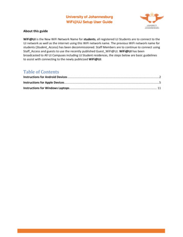
IntroductionVFC400-WiFi User Guide5IntroductionThe Control Solutions VFC400-WiFi temperature data logger automatically uploads real-time temperaturedata1 to your Control Solutions Online cloud account via your existing wireless network. It features a large,easy-to-read display, along with many familiar attributes known from the Control Solutions family of dataloggers. These include non-volatile memory for up to 16129 temperature readings and a statistical memory,storing maximum and minimum reading as well as alarm duration for each of the last 30 days.During recording the display shows the current temperature (of the most recent reading)the alarm status, current time and battery statusan alarm trigger summary of up to the last 30 days (today and 29 days previous)the wireless and cloud connection statesAt set intervals the VFC400-WiFi uploads these data to your Control Solutions Online cloud account, where theycan be viewed, analyzed and shared with others, or downloaded for further analysis.Logged temperature data can also be viewed on any PC by plugging the unit into a computer’s USB port via amicro-USB cable, for example if a Wireless Network is unavailable. View a PDF file, which can be accessedusing PDF software such as Acrobat Reader, or download the data to the free companion software ControlSolutions VTMC, where you can display data in chart, list or summary formats.FeaturesThe VFC400-WiFi temperature logger features a large display, wireless and USB connectivity with a familiarLogTag feel.1 Please refer to Transferring data to LogTag Online (on page 18) for detailed information about upload frequency
FeaturesVFC400-WiFi User Guide6CaselllllMounting lug for secure fastening of logger to fixturesMicro-USB socket with attached protective capGold-plated, high-quality temperature sensor socketRobust polycarbonate case, IP512 user replaceable AAA backup batteries, accessible via a compartment at the rear of the productButtonslllSTART/CLEAR/STOP button( ); can be used to start and stop the unit. An active alarm is cleared usingthis button. It is also used to exit the statistics review.REVIEW/MARK button ( ); can be used to enter the statistics review and to scroll through thestatistical data directly on the display. It is also used to place an inspection mark in the data listing andto reset the min/max display.FN button ( ); press together with one of the other buttons to upload data or enter Airplane mode.Display and LEDThe extra large display shows current, minimum and maximum temperatures and if alarm events haveoccurred for the current day and up to 29 days in the past. Details of any alarm event can be checked byinspecting the statistics history on the logger's display or in more detail via your LogTag Online cloudaccount. In addition, a red Alarm LED shows if an alarm event has occurred.SensorsThe VFC400-WiFi will accept any sensor from the ST100 product range, up to 3m length.CommunicationThe VFC400-WiFi offers two means of downloading data1. Via the built-in Micro USB socket and connection to a PC2. Via WiFi connection to Control Solutions OnlineThe unit is configured via a PC using Control Solutions VTMC.Power SupplyThe same USB socket that is used for communication is also used for providing power to the VFC400-WiFi,using an external 5V USB power supply. The AAA backup batteries maintain all functionality when USB poweris not connected. A long-life CR2032 lithium backup battery maintains essential functions if the AAA batteriesare empty and external power is not supplied.PDFThe VFC400-WiFi will generate a detailed PDF report when plugged into a USB port of a PC. The PDF reportshows a summary of the trip, presents the data in chart and list format and also includes a day summary page,showing an overview of the statistics collected. A CSV file of the data list is also available.
What You NeedVFC400-WiFi User Guide7What You NeedRequired ItemsIn addition to your Control Solutions VFC400-WiFi Vaccine wireless temperature monitoring logger you willneed the following:llllllla Control Solutions Cloud Account for storing and accessing uploaded dataa PC or mobile device with a modern web browser to set up your account and to view the dataa WiFi network capable of WPA/WEP security and an internet connection for uploading data to the cloudservera Micro-USB to USB-A cable to connect the VFC400-WiFi to your PCan external probe.You can use any probe of the ST100 seriesfor configuration - a PC running Windows 7 or later and Control Solutions VTMC version 3 installeda 5V/5W USB power supply to power the unit permanently via the USB socketOptional ItemsIn addition to the above, following items are useful accessories:l2 x AAA batteries as a backup if main power failsFor optimum performance we recommend Lithium Iron Disulphide batteries, such asEnergizer Ultimate Lithium Batteries, or similar batteries from other reputablemanufacturers.la small Phillips screwdriver to open the battery compartmenta wallmount bracket, which can be used, for example, to attach the VFC400-WiFi to the side of a fridgela Glycol buffer, which simulates environmental behaviour of a vaccine viall
Preparing a VFC400-WiFi for first useVFC400-WiFi User GuidePreparing a VFC400-WiFi for first useBefore your VFC400-WiFi can record temperature data and upload readings to LogTag Online you need toperform a few setup steps.In the officeThese steps are completed in your office, using a PC connected to the internet.lllllinstall the backup batteries into the unitdownload and install the latest version of Control Solutions VTMC 3. You can do this from the ControlSolutions, Inc. Software Download pageconfigure the unit using Control Solutions VTMCconnect the VFC400-WiFi to your wireless network using the LogTag Online Connection Wizardcomplete the device setup in LogTag Online, including associating the VFC400-WiFi with a locationOn-siteOnce you have completed this process you can take the logger to the location where it will be installed andllllconnect external powerconnect a sensor and place the unit, preferably using a wall mount bracketstart the loggertest the connection to LogTag Online to verify data can be successfully uploaded.You can find more information about connecting and setting up your network connection in WirelessConnectivity on page 18.8
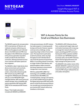
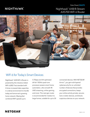
Preparing a VFC400-WiFi for first useVFC400-WiFi User GuideInserting the BatteriesThe VFC400-WiFi operates with two AAA backup batteries.1. Remove the screw from the rear compartment lid.2. Remove the lid, exposing the battery compartment.3. Insert the AAA batteries in the correct orientation, as shown. The polarity is marked inside the batterycompartment.4. Replace the rear cover and the screw.5. Press any button to turn on the display.9
Preparing a VFC400-WiFi for first useVFC400-WiFi User Guide10Configuring the VFC400-WiFi for loggingBefore a VFC400-WiFi logger can be used, it must be configured with the parameters required forllllstarting and recording temperature valuestriggering alarmsconnecting to the local WiFi networkconnecting to your cloud accountThis is done using Control Solutions VTMC software, which can also be used for downloading and analyzingdata. Control Solutions VTMC includes the LogTag Online Connection Wizard, which will allow you to setwireless and network settings and register the VFC400-WiFi against your Control Solutions Online account.llllStart the Control Solutions VTMC software.Remove the protective cap from the logger's USB socket and plug the Micro USB end of the cable intothe socket. Plug the other end of the cable into a USB socket on your computer and wait for the drivers tobe installed.Slot the logger into the interface, contacts facing down and towards the rear of the interface.From the menu click LogTag - Configure; Control Solutions VTMC will display the contents of yourVFC400-WiFi for reviewing or editing configuration settings.Standard Configuration SettingsThe standard configuration is similar to those of other LogTag logger products and includes settings such asUser ID, start method, pre-start recording, logging interval and duration, start delay, and password.Adjust the settings as required. For detailed information about each parameter please read the section aboutConfiguring a LogTag for logging in Control Solutions VTMC’s User Guide or press F1 for help.
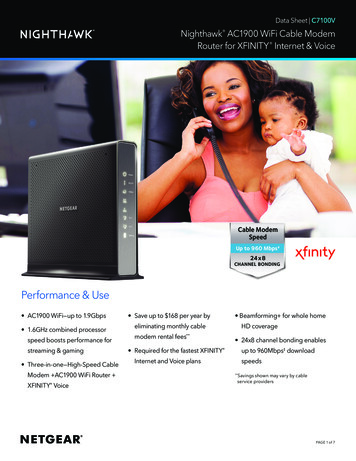
Preparing a VFC400-WiFi for first useVFC400-WiFi User Guide11VFC400-WiFi Start OptionsDuring configuration with Control Solutions VTMC you can decide when the VFC400-WiFi starts takingtemperature readings:Push button startThe logger will start taking temperature readings as soon as you have pressed the START/CLEAR/STOP button(see Starting the Logger on page 29).When you choose the push button start option, you can select to record Pre-start readings or Begin recordingafter a delay:llIf you select pre-start readings, the VFC400-WiFi starts recording as soon as it is configured and willcontinue to do so until you start the unit. No alarms are processed while pre-start readings are beingtaken, pre-start readings will not appear in the PDF file, and no PDF file will be generated. Using pre-startreadings is a good way to avoid data loss if you forget to start the unit, as you can still access the datausing Control Solutions VTMC.If you configure the VFC400-WiFi to start after a delay period, the logger will not immediately recordtemperature readings after you have pressed START/CLEAR/STOP, but start a countdown timer instead,and record readings only after the timer has ended. The value for the timer is set during configuration. Ifenabled, it will continue to take pre-start readings.Date/Time startThe logger will start taking temperature readings at the date and time you specify (local time). You cannotcombine a date/time start with pre-start readings or the start delay function.Alarm Configuration OptionsThe VFC400-WiFi can display an alarm if either of the configured alarm trigger conditions have been met. Thisis indicated on the display by showing the Alarm Indicator ( ) and the Day Alarm Marker fortoday (). Additionally, the red LED will blink every 4 seconds.If an alarm is triggered, a notification is also sent immediately to your LogTag Online account.Each alarm trigger condition consists of a threshold temperature value, an activation type (which can beinstant, consecutive or accumulative1) and a delay time, if it is not an instant alarm.If an alarm trigger condition requires readings to exceed an upper threshold temperature it is called an upperalarm. If an alarm trigger condition requires readings to go below a lower threshold it is called a lower alarm.All alarm trigger conditions are configured in the Alarm Settings tab during configuration of the logger withControl Solutions VTMC.The screen shows an example where:1lllInstant one temperature reading is above (below) the thresholdConsecutive temperature readings are above (below) the threshold for the time defined in the activation delay without interruptionAccumulative temperature readings are above (below) the threshold for the total time defined in the activation delay time, but may not necessarilybe sequential
Preparing a VFC400-WiFi for first usellVFC400-WiFi User Guide12the upper alarm is triggered when the temperature is 10.0 C or above for an accumulative time of 10hours.the lower alarm is triggered when the temperature is -0.5 C or below continuously for 1 hour.Once an alarm has triggered, the alarm indicator ( ) remains shown until the unit is reconfigured. The dayremains shown until midnight, then it turns off and the marker for the previous day is shownalarm marker() to indicate the alarm was registered against what is now the previous day. When midnight passes next,this marker will move to and so on.Alarm Re-triggeringA note on alarm re-triggering: As soon as an alarm is triggered, the corresponding delay time (but notany others) resets to zero and alarm processing starts again. The alarm processing for all other alarmdelays is not affected. Therefore, accumulative or consecutive alarms will re-trigger, if the alarmconditions are met again, and the Alarm Indicator ( ) and the Day Alarm Marker () will be shown,even if any previous alarm was cleared. Clearing an Alarm does not reset any of the delay values.File SettingsSelect the File Settings tab for the settings that decide which files are generated when the VFC400-WiFi isplugged into a computer's USB port, and what information these files contain.Select as many file formats as you wish to generate.Parameters that influence the appearance of all files are:lsetting of the temperature units used in the filesThe temperature unit for the PDF file is also used for the units shown on the display.
Preparing a VFC400-WiFi for first usellVFC400-WiFi User Guide13date and time formattime zone and MKT valuesParameters specifically influencing the appearance of the PDF file are:llllscaling parameters for the chartshowing or hiding gridlinesshowing or hiding alarm threshold linescreation of the data listFor detailed information about each parameter please read the section about Configuring a LogTag for loggingin Control Solutions VTMC’s User Guide or press F1 for help.These settings only apply to the files generated when plugging the VFC400-WiFi directly into a PC.Settings for the appearance of online reports are made in LogTag Online.
Preparing a VFC400-WiFi for first useVFC400-WiFi User Guide14Advanced SettingsSelect the Advanced Settings tab for additional configuration settings. These settings decide how some of theelements are displayed on the unit's own display and also set other options specific to the VFC400-WiFi.Parameters that influence the appearance of the display arelAllowing a user to reset the trip's minimum and maximum values on the display during recordingParameters influencing specific behaviour of the VFC400-WiFi arellleaving the alarm turned on, even if readings return to the normal temperature range againallowing the user to stop the logger with the START/CLEAR/STOP buttonFor detailed information about each parameter please read the section about Configuring a LogTag for loggingin Control Solutions VTMC’s User Guide or press F1 for help.Wireless and Network Connection SettingsThe VFC400-WiFi's wireless connection parameters are set up on the WiFi Settings tab.Select Leave wireless and network settings unchanged if you are only changing the logging parameters, butwant the VFC400-WiFi to connect to the same network as before. Selecting this option will retain the wirelessand network parameters currently stored inside the unit.Select Start the Control Solutions Online Connection Wizard if you need to enter new settings, or amendexisting settings. In this case the Control Solutions Online Connection Wizard will start as soon as ControlSolutions VTMC has finished configuring the VFC400-WiFi for logging. Factory-new units do not have anysettings and you will need to run the wizard to connect these to LogTag Online.
Preparing a VFC400-WiFi for first useVFC400-WiFi User Guide15Finalizing the configurationClick Configure to upload the configuration data to the VFC400-WiFi.If selected, the LogTag Online Connection Wizard will now start.When the configuration is complete, unplug the VFC400-WiFi from the USB socket and replace the protectivecap.If you wish to configure more VFC400-WiFi units with the same configuration, insert the next loggers into theUSB socket, wait until they are ready for configuration and click Repeat Configure. Alternatively you can use theProfile function to configure multiple units with the same settings.You can upload the configuration to a VFC400-WiFi logger as often as required.LogTag Online Connection WizardIf you have selected Start the Control Solutions Online Connection Wizard during the configuration of theVFC400-WiFi, the wizard will now start.The LogTag Online Connection Wizard is a separate program thatlllregisters the VFC400-WiFi against your accountenables you to create an account with Control Solutions Online (or sign in if you already have an account)allows configuration of wireless and network parameters of your VFC400-WiFiYou can find detailed information about the LogTag Online Connection Wizard in its online help athttp://www.vfcdataloggers.com/lto/.The LogTag Online Connection Wizard starts after the logger has been configured for other parameters suchas logging and alarms. When the wizard runs, the wireless and network parameters you enter are used tocheck that the VFC400-WiFi can establish a connection with your wireless network and the LogTag Onlinecloud server. The VFC400-WiFi's display will update during these connection checks.Initially, the display shows the logger is ready to be started.When the Wizard displays Testing Connection, please wait,first, the wireless connection is tested. If the connection issuccessful, the screen on the right shows.If the wireless connection does not succeed, the "No wirelessconnection" symbol () is shown instead, and the testaborts.Please refer to the section about Troubleshooting (on page 22)for reasons why the wireless connection can fail.
Preparing a VFC400-WiFi for first useVFC400-WiFi User GuideAfter successful completion of the wireless network test, theWizard establishes a connection between the VFC400-WiFiand the LogTag Online cloud server. When completedsuccessfully, the screen on the right shows.Please refer to the section about Troubleshooting (on page 22)for reasons why the cloud server connection can fail.The VFC400-WiFi is now ready to be deployed.16
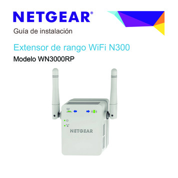
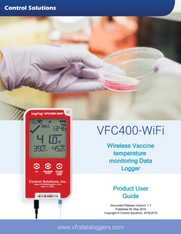
Preparing a VFC400-WiFi for first useVFC400-WiFi User GuideAdding the Sensor and the Power SupplyBefore the VFC400-WiFi can record temperature data you will need to connect an external sensor.The VFC400-WiFi accepts any ST100 sensor. Plug the sensor into the socket located at the bottom of thedevice, as shown below.For stationary applications we strongly recommend you connect a powersupply (see Powering the VFC400-WiFi).Remove the protective cap and insert the USB connector.Note that the wider part of the connector is oriented towards the rear of theproduct.17
Wireless ConnectivityVFC400-WiFi User Guide18Wireless ConnectivityThe VFC400-WiFi is designed to upload real time data to the LogTag Online cloud application. To do this, thelogger must be connected to a wireless network (WLAN) and be able to connect to Control Solutions's cloudservice on the internet.Before real-time data can be uploaded, a number of setup steps need to be completed:lYou need to have access to a LogTag Online account.lYou can create an account by navigating to http://logtagonline.com and clicking Create an Account. Youcan also use the LogTag Online Connection Wizard to navigate to this page.The logger needs to be configured for connecting to your network and to LogTag Online.llThis is done with the Control Solutions Online Connection Wizard during the logger's configuration.The logger needs to be registered against your team's account.The LogTag Online Connection Wizard will automatically register the VFC400-WiFi for you if youprovide your sign in details when you run the Wizard. You can also register the device by signing in toyour LogTag Online account at http://logtagonline.com and completing the steps for deviceregistration.The logger needs to be associated ("attached") to a location.The logger's uploaded real-time readings will only appear in LogTag Online, if you have allocated aplace where the data can be stored. In LogTag Online this is called a location, and associating thelogger with this location is called attaching the logger.Unlike other loggers uploaded via one of the wireless interfaces a VFC400-WiFi does notgenerate files on Control Solutions Drive.You can find more information about locations, device registration and attaching loggers in the LogTag Online help.Before you start the LogTag Online Connection Wizard please make sure you have following information:lllllYour wireless network name (the network SSID)Your wireless network password (WiFi password)Your LogTag Online account name (email address)Your LogTag Online sign in passwordIf you are part of more than one team, the name of the team for which you want to register the loggerTransferring data to LogTag OnlineTemperature readingsData recorded by the VFC400-WiFi are stored in internal memory, ready to be uploaded to the LogTag Onlinecloud server. The upload to the server is taking place at pre-determined times that cannot be changed:lIf the logger is permanently powerd via USB power supplyThe upload to the server takes place every log interval, or multiple thereof, but no sooner than every 5minutes.For example, a logger that records every 2 minutes will upload readings to the cloud server every 6minutes, a logger that takes a reading every 15 minutes will upload readings to the cloud server every 15minutes.
Wireless ConnectivityVFC400-WiFi User Guide19If a logger is scheduled to take a temperature reading and also upload readings to the server atthe same time, the temperature reading will always be taken first before the upload starts.lIf the logger is powered via the AAA batteriesThe upload to the server takes place every log interval, or multiple thereof, but no sooner than every 60minutes.For example, a logger that records every 15 minutes will upload readings to the cloud server every 60minutes, a logger that records every 45 minutes will upload readings every 1½ hours.AlarmsAs soon as a VFC400-WiFi triggers an alarm, this is reported to the cloud server immediately, regardless of theupload interval for temperatures.Wireless and Cloud SymbolsOn the display, wireless connection and link to the LogTag Online cloud server are shown using the wirelessand cloud connectivity symbols.This symbol shows the status of the last connection to the wireless network (WLAN). If the circleshows a tick, the VFC400-WiFi 's last connection to the wireless network was successful.When USB power is supplied, the VFC400-WiFi remains connected to the WLAN.This symbol is shown when the last connection to the wireless network was successful and thedevice is powered by batteries.When the VFC400-WiFi is powered by the AAA batteries, it does not remain connected to the WLANto preserve battery power. Instead, the connection is re-established automatically at the nextscheduled data upload to the LogTag Online cloud server.This symbol shows the status of the last connection to the LogTag Online cloud server. If the circleshows a tick, the VFC400-WiFi 's last connection to LogTag Online was successful.This symbol shows while the VFC400-WiFi is transmitting data to the LogTag Online cloud server.Typically you will see wireless and cloud symbols together, unless there is an issue. Please seeTroubleshooting on page 22 for further details about the various symbol combinations that can be displayed.
Wireless ConnectivityVFC400-WiFi User Guide20Testing your wireless and network connectionYou can verify that uploading data to the LogTag Online cloud server is working by initiating a ConnectionTest directly from the VFC400-WiFi.During the connection test the logger willllllllconnect to your wireless network using the network name and password you entered during the setupwith the LogTag Online Connection Wizardconnect to the LogTag Online cloud serverexchange a pre-defined set of messages with the cloud server that verify the device's identityrequest any information from the server such as the current timeupload any new temperature and event data that have been recorded since the last connection to thecloud serverclose the connectionThis will give you immediate feedback if the logger's wireless and network settings were configured correctly.To initiate the connection test, press and hold the FN andREVIEW/MARK buttons simultaneously for approx. 6seconds. During this time the Upload arrow symbol ( ) on thedisplay blinks.Release the buttons when the symbol stops blinking and turnson permanently.The VFC400-WiFi will now attempt to access the wirelessnetwork (the WLAN symbol shows an empty circle).This process is typically very short, so you may not see thisscreen.Once the VFC400-WiFi has successfully connected to thewireless network (the WLAN symbol shows a tick) it willattempt to connect to the LogTag Online cloud server (Cloudsymbol shows an empty circle).Depending on network traffic this can take a few seconds.
Wireless ConnectivityVFC400-WiFi User GuideThe VFC400-WiFi has successfully established a connectionto the LogTag Online cloud server (Cloud symbol shows atick).The VFC400-WiFi is now exchanging data with LogTag Online, indicated by an arrow inside the cloud symbol ( ).The arrow may turn on and off repeatedly during the dataexchange.The logger has successfully completed its initial connectionprocess.The Cloud and WLAN symbols remain to indicate that the lastconnection was successful.The Devices page in LogTag Online will be updated with the last connection time.If the wireless or cloud communication fail, WLAN or Cloud symbols may show a cross. Please refer to thesection about Troubleshooting (on the next page) for further details.This connection test is performed automatically every time the VFC400-WiFi takes the first reading of a newtrip.You can initiate this test manually at any other time, provided valid wireless and network conection settingsare stored in the logger.21
Wireless ConnectivityVFC400-WiFi User Guide22TroubleshootingTo successfully upload data to LogTag Online, your VFC400-WiFi needs to be connected to your wirelessnetwork and be able to access the LogTag Online cloud server. It also needs to be registered to your team'saccount and must be attached to a location.If the connection has succeeded and data have been uploaded the wireless and cloud indicators on the displayshow as follows:lIf your logger is connected to power:lIf your logger operates on batteriesIf yo
The VFC400-WiFi will accept any sensor from the ST100 product range, up to 3m length. Communication The VFC400-WiFi offers two means of downloading data 1.Via the built-in Micro USB socket and connection to a PC 2.Via WiFi connection to Control Solutions Online The unit is configured via a PC using Control Solutions VTMC. Power Supply