Transcription
Technical ReportESSA RESEARCH LABORATORIESA Survey of Microwave FadingMechanisms Remedies andApplicationsMARCH 1968Boulder, ColoradoERL 69-WPL 4
ESSA RESEARCH LABORATORIESThe mission of the Research Laboratories is to study the oceans, inland waters, thelower and upper atmosphere, the space environment, and the earth, in search of the understanding needed to provide more useful services in improving man's prospects for survivalas influenced by the physical environment. Laboratories contributing to these studies are:Earth Sciences Laboratories: Geomagnetism, seismology, geodesy, and related earthsciences; earthquake processes, internal structure and accurate figure of the Earth, anddistribution of the Earth's mass.Atlantic Oceanographic Laboratories and Pacific Oceanographic Laboratories: Oceanography, with emphasis on ocean basins and borders, and oceanic processes; sea-air interactions; and land-sea interactions. (Miami,, Florida)Atmospheric Physics and Chemistry Laboratory: Cloud physics and precipitation;chemical composition and nucleating substances in the lower atmosphere; and laboratoryand field experiments toward developing feasible methods of weather modification.Air Resources Laboratories: Diffusion, transport, and dissipation of atmosphe'r ic contaminants; development of methods for prediction and control of atmospheric pollution. (Silver Spring, Maryland)Geophysical Fluid Dynamics Laboratory: Dynamics and physics of geophysical fluidsystems; development of a theoretical basis, through mathematical modeling and computersimulation, for the behavior and properties of the atmosphere and the oceans. (Washington,D. C.)National Hurricane Research Laboratory: Hurricanes and other tropical weather phenomena by observational, analytical, and theoretical means; hurricane modification experiments to improve understanding of tropical storms and prediction of their movement andseverity. (Miami, Florida)National Severe Storms Laboratory: Tornadoes, squall lines, thunderstorms, and othersevere local convective phenomena toward achieving improved methods of forecasting, detecting, and providing advance warnings. (Norman, Oklahoma)Space Disturbances Laboratory: Nature, behavior, and mechanisms of space disturbances; development and use of techniques for continuous monitoring and early detectionand reporting of important disturbances.Aeronomy Laboratory: Theoretical, laboratory, rocket, and satellite studies of the physical and chemical processes controlling the ionosphere and exosphere of the earthand other planets.Wave Propagation Laboratory: Development of new methods for remote sensing of thegeophysical environment; special emphasis on propagation of sound waves, and electromagnetic waves at millimeter, infrared, and optical frequencies.Institute for Telecommunication Sciences: Central federal agency for research and services in propagation of radio waves, radio properties of the earth and its atmosphere, natureof radio noise and interference, information transmission and antennas, and methods forthe more effective use of the radio spectrum for telecommunications.Research Flight Facility: Outfits and operates aircraft specially instrumented for research; and meets neecls of ESSA and other groups for environmental measurements foraircraft. (Miami, Florida)ENVIRONMENTAL SCIENCE SERVICES ADMINISTRATIONBOULDER, COLORADO
U. S. DEPARTMENT OF COMMERCEc.R. Sm ith, SecretaryENVIRONMENTAL SCIENCE SERVICES ADMINISTRATIONRobert M. White, Adm in istratorESSA RESEARCH LABORATORIESGeorge S , Benton, DirectorESSA TECHNICAL REPORT ERL69- WPL 4A Survey of Microwave FadingMechanisms Remedies andApplicationsH. T.DOUGHERTYWAVE PROPAGATION LABORATORIESBOULDER, COLORADOMarch 1968For sale by the Superintendent of Documents, U.S. Government Printing Office, Washington, D.C. 20402Price 50 cents .
TABLE OF CONTENTSLIST OF FIGURESivABSTRACT . . .11.INTRODUCTION12.REFRACTIVE INDEX GRADIENTS43.FADING MECHANISMS103. 1.Mu1tipath Fading123.2.Power Fading .3.3.4.5.6.173.2. 1.Power Fading Due to Diffraction193.2.2.Power Fading Due to Antenna .243.2.3.Power Fading Due to Ducts and Layers253.2.4.Fading Due to Precipitation.26Combinations of Fading Mechanisms263.3. 1.K- Type Fading263.3.2.SurfaceDuctFading29DISTRIBUTION CURVES FOR MULTIPATH FADING334. 1.The Relative Amplitudes of the Mu1tipath Components334.2.The Received Signal Amplitude Distributions35PROTECTION AGAINST MULTIPATH FADING455. 1.Separations for Frequency Diversity .465.2.Multipath Parameters .5.3.Separations for Space Diversity.5259FADING REMEDIES AS MEASUREMENT TECHNIQUES606. 1.Diffraction Fading as a Measurement Technique .616.2.Diversity Reception as a Measurement Technique.63CONCLUSION . . . . . . . . . . . . . . .8.ACKNOWLEDGMENT709.REFERENCES.71APPENDIX . . . . .687.A-IIII
LIST OF FIGURESFigure 1.The bending of radio rays for linear gradients6Figure 2.Effective earth radius factor versus the linear refractiveindex gradient7A distribution of refractive index gradients averaged overthe first 50 and 100 mete rs above the surface .8Figure 3.Figure 4.Surface superrefractive layer due to radiation11Figure 5.Multipath fading mechanisms .13Figure 6.Example of multipath fading .14Figure 7.Example of frequency selectivity for multipath fading16Figure 8.A ttenuation fading mechanisms18Figure 9.Attenuation curves for a 2-GHz propagation path20Figure 10.Diffraction fading due to layering .22Figure 11.Attenuation of a field due to diffraction by a smoothspherical earth at exactly grazing conditions and relativeto the free space field .23Figure 12.Illustration of the variation of field strength with refractiveindex gradient, k-type fading .28Figure 13.Surface duct fading mechanism30Figure 14.Examples of surface duct propagation for effective earthradius and true earth radius32The amplitude distributions for a constant componentplus a Rayleigh distribution, K2: 1 .36The amplitude distributions for a constant componentplus a Hoyt distribution, K2 238The amplitude distributions for a constant componentplus a Hoyt distribution, K2: 339The amplitude distributions for a constant componentplus a Hoyt distribution, K2: 540The amplitude distributions for a constant componentplus a Hoyt distribution, K2: 10 .41Figure 15a.Figure 15b.Figure 15c.Figure 15d.Figure 15e.lV
Figure l6a.Figure l6b.Figure 17.Figure 18.Figure 19.Figure 20.The distribution for two-component multipath (direct plusa reflected field) .The distribution for two-component multi path (aplus a Rayleigh distributed signal43 1.0)44Diagram for deriving the minimum frequency diversityseparations49Minimum frequency diversity separations for reflectiveand refractive multipath50Graphical location of some of the permissible andforbidden frequency separations for a specified protectionagainst multipath fading51Illustrative interference pattern for multipath fading dueto specular ground reflection and the minimum frequencydiversity for protection to 20 dB .53Figur e 21 a.The normalized relationship between path length differ enc eand effective earth curvature54Figur e 21 b.The normalized relationship between path length differ enc eand effective earth curvature56Figure 21c.The normalized relationship between path length differenceand effective earth curvature57Figure 22.An illustration of space and frequency diversity dependenceupon path length difference59Figure 23.Attenuation versus gradient of refractive index for pathswhich are grazing for k 4/362Figure 24.A sweep frequency display of diversity reception64Figure 25.Graphical determination of the received signal envelopes66Figure A-I. Schematic diagram for the derivation of the angle of arrival A2v
A SURVEY OF MICROWAVE F ADillG MECHANISMS AND REMEDIESH. T. Doughe rtyAfter a brief description of the significance of theradio refractive index and its variation in the lowertroposphere, a catalog of fading mechanisms is presented. Attention is directed to the supporting refractive index structure, the characteristics of thefading signal, and the available remedie s. Thephenomena of multi path fading are de sc ribed, andthe theo retical amplitude distributions are pre sented.Diversity reception (frequency or space) is outlinedfor reducing the fading due to multipath. Specificexpressions are given for determining the frequencyor space separations.Successful remedies for microwave fading that arekeyed to specific fading mechanisms also constitute ameans of measuring the characte ristic s of the prevailing meteo rological condition s. Specific expre s sionsare given to accomplish this for the multipath anddiffraction fading mechanisms.1.INTRODUC TIONIt is well known that changes in the radio refractive indexstructure along nominally line-of-sight propagation paths cause variationof the received signal level.For most line-of-sight communicationsystems most of the time, this signal variation is not serious.se rious variation, fading,Theis gene rally limited to systems ope ratingin the upper UHF and the SHF frequency bands in certain geographicallocations and at particular times of the day and year.A wealth ofexperience pertinent to this fading has been provided by the effortsof experimentalists and system operators over the last two decades.
Much of the experimental data has been de'scribed by Beckmann andSpizzichino (1963) and abstracts of many of the published reports areavailable (Dougherty, 1964).This experience must now be madeavailable in a form readily assimilated by the systems engineer andfuture investigators.This requires a proper cataloging of fading mterms of the prevailing propagation mechanisms, the associatedmeteorological and terrain conditions, the observable fading characte ristic s, and the advantage s and limitations of the available remedie s.This is the first report of a study undertaken at the ESSARe search Laboratories.The pur pos e is to determine a proper cataloging,with two applications in mind.First, the cataloging should permit thesystems engineer to diagnose a fading situation and select the mosteconomic and effective remedy--at least to the extent permitted bythe expe rience accumulated to date.Second, the cataloging shouldpermit the design of critical experiments to test and to extend ourunderstanding of fading phenomena.Initially, the study involves thefields of wave propagation, meteorology and statistics, but musteventually involve the fields of modulation systems and techniques.The latter is necessary because fading involves not just variations ofsignal amplitude, but also of the phase, angle of arrivaljand polarizationof the received signal.The most basic definitions of fading are in terms of the propagationmechanisms involved: refraction, reflection, diffraction, scattering,focusing, attenuation, etc., as well as the guiding of radio waves.These are basic because they determine the statistical behavior withtime of the measurable field parameters (amplitude, phase} and polarization) and the frequency and spatial selectivity of the fading.Thesemechanisms are also basic because the most efficient fading remedie sare keyed to recognizing the causative mechanism.2They are encountered,
however, only in the presence of certain associated conditions classifiedas meteorological situations and terrain geometry.The se conditionsare usually related in severe fading situations, and, in most cases,sufficiently understood to be categorized in terms of why, where, and when.Although the predictability of these associated conditions is not suitablefor inclusion in the formal telecommunication system design procedures,it can be described so that the systems engineer can avoid the more obvious·· causes of fading in the course of his site survey.Because some systems engineers may not be familiar with thevariation of radio refractivity near the earth·s surface, this reportwill first attempt to summarize (section 2) what is known about certainaspects of the radio refractive index (its structure and variation) thatare significant for microwave fading.In section 3, the fading mechanismsare classified and illustrated in terms of the supporting refractive indexstructure and the terrain geometry.The fading characteristics aredescribed, qualitatively, and the available remedies are discussed ingeneral.Section 4 presents the families of theoretical distributions,i. e., the amplitude fading distributions that would be expected formultipath fading mechanisms.The multi path fading mechanisms arediscussed further in section 5)and the reduction of their effects, bydiversity system design, is detailed.Section 6 treats the use ofmultipath and diffraction fading remedie s, as technique s to measurethe characteristics of the supporting meteorological and terrainconditions.Section 7 briefly summarize s the regions in whichfurther study is particularly needed.3
2.REFRACTIVE INDEX GRADIENTSThis section briefly desc ribe s some of the available informationabout the refractive index structure near the earth's surface that issignificant in connection with mic rowave fading mechanisms.The average bending of an electromagnetic wave propagatedthrough the troposphe re may usually be repre sented by ray theory(Bean, 1964; Born and Wolf, 1964; Bean and Dutton, 1966) in terms ofa radius of ray curvature related to the average gradient of refractiveindex (Schelleng, Burrows and Ferrell, 1933; Millington, 1946, and1957; Dutton and Thayer, 1961; and Beckmann, 1962).If we assumethat the refractive index n of the air varies linearly with the height hfor the first few tenths of a kilometer above the earth's surface anddoes not vary In a horizontal direction, then the radius of curvaturer of the radio ray relative to the radius of the earth, rO 6370 km,may be expressed in terms of the gradient, D.n/D.h, by:( 1)The parameter k is sometimes known as the effective earth-radiusfactor.The gradient is usually expressed in terms of the refractivity,6N ::: (n-1) 10 , so that::: N H10-6N units/km ,(2)and(3)4
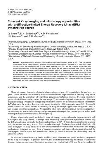
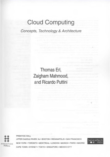
Several values of k and N/Ah are listed in figure 1, where the corresponding ray paths are illustrated.The vertical scale of figure 1 isexaggerated, relative to the horizontal scale, to ITlake the differencesin curvature noticeable.For 0 k 1.0, encountered for positive gradients (subrefractiveconditions), the ray curves away froITl the earth so that the ray joiningtwo terITlinals passes close to the earth.The ray ITlay even be interruptedby the surface (k::: 0.33 in fig. 1) so that the receiving terITlinal isbeyond radio line of sight.For the cOITlITlonly encountered situations-157 ANI Ah ::; 0 wh8re co k 1.0, the rays are bent toward theearth's surface.At the critical value AN/Ah::: -157 N units/kITl,Ik I::: co and the curvature of the ray path is equal to the curvature ofthe earth; the rays follow straight paths relative to the earth's surface.For ANI Ah -157, the situation is supe rrefractive and the value of k,given by (3), is negative.For negative values (Hufford, 1967), theray paths are bent sufficiently toward the earth's surface so thattrapping of the radio rays is possible.ANI Ah Because of that possibility,-157 is cOITlITlonly referred to as a trapping or ducting condition.The relation between the values of k and e::.N/A h, discussed above andgiven by (3), is plotted in figure 2.To illustrate that the range of conditions shown in figure 1 isrealistic, a distribution of average gradients for Cape Kennedy,Florida) is pre sented in figure 3.The distribution was dete rITlined froITlFebruary, May, August) and NoveITlber data selected froITl a 7· yearperiod.This figure is based on data froITl the World Radio RefractiveIndex Data Center at the EnvironITlental Science Services AdITlinistration,Boulde r, Colorado.PreliITlinary inve stigations for othe r locationsthroughout the world indicate that figure 3 at least exeITlplifies ITlaritiITleor coastal locations with relatively SITlooth terrain.5Much of the
THE BENDING OF RADIO RAYS FOR LINEAR GRADIENTSk -\k rok I""'k 0.5. --.k 0.33-----------,-./"A'.//"/"*,0.N,0.hl/'3141 0.330'*TERRAINFigure Ik1570.501.0-157ro-314-1.0N UNITS! km
EFFECTIVEEARTHRADIUS FACTOR VERSUS THELINEARREFRACTIVEINDEXGRADIENT109'8 f- ·. i.'! '!!"1I;"!: !! , ; c' '-I-T, ;-,.,-t' ,T; ' -Jfl'm-t'\t' ,-t,- ,-c, :- ;- ;-,; '-t·.i'- ' .l- ;- ;-i'-i-i-i-i-rlf-Ho-H-i-i;'--:'-;"-:-i-i'; ·.-;-.i- I-.1-.1-. 1-;L:I .i ' -;4-1;CCof-U11.(f) o ICCIfCC I.T .ww 0.9I-: 1 t, . l, ! j.:; i, '"0.' "-, .;i:' f-;u.-:'"L-lwu.u.wu.jowo fZ .: I::;:" 1t-. C NVEX0.3CONCAVE EARTHJ -EARTH-, t ttttl', -1It -, :.1. ." J -157.1 (PLANE EARTH CONDITION:tI- :iki-ro)i-t " .-H- - TT I':-t t H-tH ,H- 300REFRACTIVE-200o-100100200INDEX GRADIENT, LlN/Llh, IN N UNITS PER KILOMETERFigure72300400
A DISTRIBUTION OF REFRACTIVE INDEX GRADIENTSAVERAGED OVER THE FIRST 50 AND 100 METERSABOVE THE SURFACEIE(f)IZ I.x.200I--- - \1\I \III:::JZIZII000IIL. J:zIII. JI-zw0 I0:: .9IIIIIIIIIIIIICOMBINED DIST1RIBUTION OF INITIAL N-GRADIENTSFOR 4 MONTHS I-200IIII FEB.- MAY.-AUG.- NOV. I1660 PROFILES (EACH CURVE)100.r, . KCONVEXEFFECTIVEI I. , -50m.0-100 m VEARTH -I-400I-430 f-- -r- I - - l - 1- - -""'" t--- r-- t--l"- I"-r-- I1----1----I-- -:0.01 0.050.5 I5 100.50.7300::0I-u ILL(f):::J0 I0::- 5025-- -5- -2 ,- ,"-EXTrAPOLyEp 90 9570% OF TIME ORDINATE VALUEFigure 3--- "r . '"CONCAVEEFFECTIVEEARTH-0.4-ICAPE KENNEDY, FLA.7 YEARS DATA:I.x-EXTRAPOLATED"1':'-IS : ' . ",r-.99 99.5EXCEEDED-II0:: Iww I--IuwLLLL-0.7 w-0.5753-0.599.95 99.99.
available information is included in a recent world atlas of refractiveindex gradients (Beanet a1., 1966).Note that the median value of figure 3 is approximately -60 Nunits/km, a departure from the commonly used median value ofapproximately -40 N units/km that is associated with the 4/3 earth.Such differences are generally negligible for transmission frequenciesof several hundreds of megahertz, or less.At microwave frequencies,however, this difference can be significant.A similar situation existsin the plotting of propagation path profiles; a 4/3 earth path profilecan be misleading--it corresponds to a situation that is not particularlysignificant for fading situations and can obscure the dynamic nature ofmicrowave propagation through the lower atmosphere.procedures are available.PreferableFor example, charts are commerciallyavailable for plotting the various ray paths between two terITlinals(such as in fig. 1) for a range of k values.This is applicable to anyprofile but avoids much computation when the profile is a simplerectangular height-versus-distance profile taken directly from a map.The ITleteorological conditions that support the microwave fadingmechanisms commonly take the form of marked departure s from medianconditions.Strong refractive index gradients occur over a limitedrange of elevation (layers) at, or above, the terrain surface.In mostcases they can be associated with known meteorological processesand described in terms of typical geographical locations and weatherconditions recognizable to the systems engineer.They also exhibittypical behavior in terms of meteorological measurements availablefrom stations of the U. S. Weathe r Bureau and can be systematizedfor quick refe rence.9
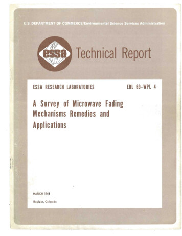
This is illustrated in figure 4, a schematic description of thosesuperrefractive surface gradients that are caused by the radiation ofheat from the surface to a clear sky.At night, clear skies and lightsurface winds permit conside rable cooling of the earth I s surface.Thiscan cause the formation of a temperature inversion (an increase oftemperature with height) and produce a strong superrefractive gradientnear the surface - -a condition that can dramatically affect mic rowavepropagation.The likelihood of extreme subrefractive or superrefractivegradients is reduced for propagation above rough terrain.Line-of-sight propagation paths between high points of mountainous te rrainwill, in general, experience more linear distributions of gr-adientswith reduced standard deviations (compared to that depicted in fig. 3).They, the refore, exhibit only slight variations in signal level (Kleinand Libois, 1953).There are exceptions to this, such as in the coastalrange of mountains of northern Chile, which are attributable to theintrusion of the trade wind inversion among the mountain peaks .Similarly, the distribution of refractive index gradients exhibit amore negative median for oversea paths (Ikegami, 1964).A detailed,informative treatment of the refraction of radio waves and the refractiveindex structure of the lowe r atmosphere may be found in a recent U. S.Department of Commerce publication (Bean and Dutton, 1966) .3.FADING MECHANISMSThe significance of the refractive index structure for microwavefading is best illustrated by the variety of the propagation situationsthat produce such fading.Here we classify and illustrate these pro-pagation fading mechanisms and identify the supporting refractive indexstructures.Only a general discussion of the fading signal characteristicsand their remedies is provided; detailed treatments are deferred tosubsequent sections.10
gicalRefractivity ProfileData200(/) (l) (l)2 (l)u0-.::J(J)100(l). :r-.(l) 0.Q !" -. :0'"wI0Warm290Dew Point, C.Refractivity in N-units / kmTemperature,Figure 4.OCCURRENCE: Clear skies and light surface winds at night penuit a considerablecooling of the earth's surface due to the radiation of heat to space.The air near the surface also cools, resulting in a temperatureinversion.0c.
The fading experienced at microwave frequencies for troposphericline-of-sight paths may be considered under two general categories:multipath fading and power fading.Each category includes severalfading mechanisms that exhibit characteristic s that often pe rmit theiridentific at ion .3. 1.Multipath FadingAs the refractive index gradient varies, multipath fading resultsfrom inte rference between the direct wave .and(a)the specular component of the ground-reflected wave;(b)the nonspecular component of the ground-reflected wavej(c)partial reflections from atmosphe ric sheets or elevatedlayers; or(d)additional direct (nonreflected) wave paths.These additional direct wave paths can occur due to either the surfacelayers of strong positive refractive index gradients (Magnuski, 1956 Nicolis, 1966) or the horizontally distributed changes inrefractive index--as may be encountered with a weather front (Misme,1957).The multipath fading mechanisms are illustrated in figure 5.The depths of fades encountered for these multipath phenomenacan be quite severe, depending upon the effective reflection coefficientsor the relative amplitudes of the component waves.and (c) can produce fades persisting for minutes.Mechanisms (a)During such fadesthe nonspecular ground·-reflected components (normally small forsmall grazing angles) can cause additional interference (with the directplus specular component»providing even deeper, more rapid, fadeshaving durations of the orde r of seconds.An illusiration of multi pathfading (direct plus ground-reflected wave) is presented in figure 6 toshow the characteristic return of signal level to, or above, the freespace value.In figure 6, a basic transmission loss (Rice12et al., 1966)
zzzen::EenZ.c.c.c«IIIu1-0W::E(.9lI)z(l)0 ::::J01Lti.L,,IIt-«0. I:::J \0vr--41\0We::.c WZ-.J-lW l W I:130-.J I:1\.cI- Z-z l
EXAMPLE OF MULTI PATH FADING(f)-'wCDuwo135z140-1'" (f)(f)g 145.,. z0(f)(f)150I z155r-160(f) l:0::1r"If 7.135 GHzd 30.5 kmh l 47.7mh2 41.2 mOCTOBER 10,1963u(f) l:165CD .0-'020003000400HOURFigure 605000600F c ""W
of approximately 139 dB co rresponds to that for thelevel.f ee - spacesignalThe multipath fading tends to be less frequen1 during the day,particularly during the afternoon hours, when conditions more closelyapproach a median or refe rence atmosphe ric structure, a condition forwhich most paths are designed.Figure 7 presents an illustration of the frequency selectivityof multipath fading.There, the recordings of received signals oftwo transmission frequencies are presented for a common propagationpath.On an instantaneous basis the two recordings appear uncorrelated.Note, howeve r, that with an allowance for time lag the two signalshighly correlated.areThis time lag for high correlation, which is a measureof the effective (frequency) diversity separation, is a function not onlyof the frequency separation, but also of the refractive index gradientand its tiYLe rate of change.Clearly, the frequency spacing of figure7 is inadequate if fades of 20 dB below the 139-dB free-space level areunacceptable.The multipath fading due to the interference from specularground reflections can be avoided by eliminating one of the fieldcomponents,by specialKawazuIIThe specularly reflected wave can be seve rely reducedanti-reflective wave" antenna arrays (Bateman, 1946;et al., 1959) or by the use of Fresnel zone screens (Bussey,1950; Ugai, et al., 1963; Preikschat, 1964).These devices assumethat the range of refractive index gradients will not be too wide.For propagation over rough irregular terrain, this last condition isusually met, and the effects of ground reflections may then, be avoidedb y the proper choice of antenna sites or antenna deSigns.To date,however, the most effective counter measure for gene ral multipathfading over wide ranges of refractive index gradients is diversity reception(Cabessa, 1955; Magnuski, 1956; Lewin, 1962; Albertson, 1964).will be treated in further detail in section 5.15This
EXAMPLE OF FREQUENCY SELECTIVITYFOR MULTI PATH FADI NG(f)--1WmUw0z 135140(f)(f)0--1z0(f)145150f 7.135 GHzd 30.5 km (f)z155hi !0:::f- 47.7mh2 41.2 mSEPTEMBER 18,1963160u(f) !m165.0--10200040003000500HOUR(f)--1WmCd 1350z (f)(f)1409z1450(f)(f) 150fd(f)z !0:::f-U(f)155 7.385 GHz 30.5 kmhi 47.7 mh2 41.2 mSEPTEMBER 18, 1963160 !m.c--1020004000300HOURFigure 7160500
3.2.Power FadingPower fading results from the partial isolation of the transmittingand receiving antennas because of:(a) intrusion of the earth's surface or atmospheric laye rs into,: the propagation path (earth-bulge fading or diffraction fading );(b)antenna decoupling due to variation of the refractive indexgradient;(c)partial reflection from elevated layers interpositionedbetween the te rminal antenna elevations;(d)IIducting" formations containing only one of the terminalantennas; and(e)precipitation along the propagation path (R yde and R yde,1945;Hunter, 1964; Medhurst, 1965; Kuhn, 1967).The received signal for the se po we r fading mechanisms is characterizedby a marked decrease in median signal level below that for free spaceand fo r extended pe riods of time.Some example s of th es e fadingmechanisms are given in figure 8 .','',When a strong atmospheric layer intrudes into the direct propagationpath between transmitter and receiver, the effect is much like thatfor intrusion of the earth's surface. For example, the ene rgy represented by ray paths which strike the surface of a superrefractivelayer, at grazing angles of more than a few milliradians, penetratesthe layer and is diverted from the direct path to the receiver location.The ray path at grazing incidence and those ray paths which pass abovethe laye r provide a contribution to the receive r in the radio hole orII shadow" of the layer via the diffracted mode of propagation.Thereceived field may be determined by ap lying the Leontovitch boundaryconditions at grazing incidence where n -1 «1 (Hufford, 1952) .17
ATTENUATIONFADINGMECHANISMShhk 1dN/dh O----- NLhELEVATEDLAYERt-oo------ I'-NhATMOSPHERICDUCTd-----IFigure 8'-N
3.2.1.Power Fading Due to DiffractionThe power fades that occur due to diffraction by the earth'ssurface are generally supported by a subrefractive (positive) gradientof refractive index.of figure 8.The situation is illustrated by the uppe r diagramThis type of fading can persist for several hours and todepths of 20 or 30 dB.The fading is essentially independent of smallscale changes of frequency, but may be reduced or avoided by a properchoice of terminal antenna heights.In mountainous terrain where terminals are located on dominatingridges or peaks, a single Fresnel zone clearance, or even less, willusually be sufficient.The clearance corresponding to n Fresnel zonesin mete rs isCn 8.66",jnd/ ,( 4)whe re the path length d is in kilomete rs and the transmis sion frequencyf is gigahertz.If only a limited range of refractive index gradients isencountered, a first Fresnel zone clearance, C , or less is sufficientl(Klein and Libois, 1953; Troitskii, 1960). For those microwave pathswhe re sub refractive index gradients are encounte red, inc rea sedclearances are required.Consider a 2-GHz, 50- kIn propagation pathwith terminal antennas at equal heights.The smooth spherical earthdiffraction loss for such a path is shown in figure 9 as a function ofantenna height and path length when the refractive index gradient is80 N units/kIn.The path length d in kilometers, the effective earthradius factor k (related to the gradient AN/Ah through (3)), and theantenna heights, hI and h2 in meters, for which the path would be justgrazing (i. e., barely line Of sight) are related by d ",j 1 Z. 74 kh 1r-::---I'.12 C). 'l"-GtI)t.\t.19",j lZ.74 khZ\'-'t,(5 )
ATTENUATION CURVES FOR A 2"- GHz PROPAGATION -----r--'----,--------,----,-.,--,--r-r-1700500 w GRADIENT :boN/boh 80 N UNITS/km300-.JW0::::200N(f)f.0::::-w5I- wZ100 «70zO::::wI-500::::1- .9IZ .9-wt;I«0::::«LLZLLZOWI-WZI«I-oW0::::30201075 oW0::::321015202530ATTENUATION IN DECIBELSBELOW FREE SPACE2351072030PATH LENGTH, d, IN KILOMETERSFigure 9.2050 70 100
This expression involves the familiar relation between antenna heightIand horizon distance over smooth ear
Re search Laboratories. The pur pos e is to determine a proper cataloging, with two applications in mind. First, the cataloging should permit the systems engineer to diagnose a fading situation and select the most economic and effective remedy--at least to the extent permitted by the expe rience accumulated to date. Second, the cataloging should