Transcription
ESP-12S User ManualREV:1.02016.7
ESP-12S User ManualFCC STATEMENTThis device complies with Part 15 of the FCC Rules. Operation is subject to the following two conditions:(1) This device may not cause harmful interference.(2) This device must accept any interference received, including interference that may cause undesired operation.Any changes or modifications not expressly approved by the party responsible for compliance could void the user’sauthority to operate the equipment.Please notice that if the FCC identification number is not visible when the module is installed inside another device,then the outside of the device into which the module is installed must also display a label referring to the enclosedmodule. This exterior label can use wording such as the following: “Contains FCC ID: 2AHMR-ESP12S” any similarwording that expresses the same meaning may be used.This equipment complies with FCC radiation exposure limits set forth for an uncontrolled environment.This equipmentshould be installed and operated with a minimum distance of 20cmbetween the radiator & your body. This transmittermust not be co-located or operating inconjunction with any other antenna or transmitter.CE Mark WarningThe module is limited to OEM installation ONLY.The OEM integrator is responsible for ensuring that the end-user has no manual instruction to remove or installmodule.The module is limited to installation in mobile application;A separate approval is required for all other operating configurations, including portable configurations with respect toPart 2.1093 and difference antenna configurations.There is requirement that the grantee provide guidance to the host manufacturer for compliance with Part 15Brequirements.
ESP-12S User ManualTable Of Contents1. Preambles . 21.1.Features . 31.2.Parameters . 42. Pin Descriptions. 52.1.Interfaces . 62.2.Pin Mode. 82.3.Antenna interface . 83. Package information and OEM installation method . 93.1.Package information . 103.2.OEM installation mathod . 104. Absolute Maximum Ratings . 114.1Recommended Operating Conditions . 114.2.AT commend Testing. 114.3.AT commend . 124.3.1.AT Command Description . 124.3.2.Basic AT Command Set . 121
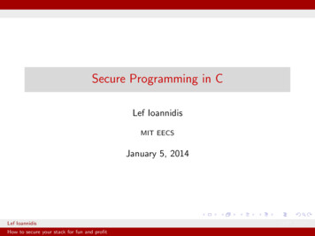
ESP-12S User Manual1. PreamblesESP-12S WiFi module is developed by AI-Thinker Co.,Ltd, core processor ESP8266 in smaller sizes of the moduleencapsulates Tensilica L106 integrates industry-leading ultra low power 32-bit MCU micro, with the 16-bit short mode,clock speed support 80 MHz, 160 MHz, supports the RTOS, integrated Wi-Fi MAC/BB/RF/PA/LNA, on-board antennas.The module supports standard IEEE802.11 b/g/n agreement, complete TCP/IP protocol stack. Users can use theadd modules to an existing device networking, or building a separate network controller.ESP8266 is high integration wireless SOCs, designed for space and power constrained mobile platform designers.It provides unsurpassed ability to embed Wi-Fi capabilities within other systems, or to function as a standaloneapplication, with the lowest cost, and minimal space requirement.Figure 1ESP8266EX Functional Block DiagramESP8266EX offers a complete and self-contained Wi-Fi networking solution; it can be used to host the applicationor to offload Wi-Fi networking functions from another application processor.When ESP8266EX hosts the application, it boots up directly from an external flash. In has integrated cache toimprove the performance of the system in such applications.Alternately, serving as a Wi-Fi adapter, wireless internet access can be added to any micro controllerbased designwith simple connectivity (SPI/SDIO or I2C/UART interface).ESP8266EX is among the most integrated WiFi chip in the industry; it integrates the antenna switches, RF balun,power amplifier, low noise receive amplifier, filters, power management modules, it requires minimal external circuitry,and the entire solution, including front-end module, is designed to occupy minimal PCB area.ESP8266EX also integrates an enhanced version of Tensilica’s L106 Diamond series 32-bit processor, with on-chipSRAM, besides the Wi-Fi functionalities. ESP8266EX is often integrated with external sensors and other applicationspecific devices through its GPIOs; codes for such applications are provided in examples in the SDK.2
ESP-12S User Manual1.1.Features 802.11 b/g/n Integrated low power 32-bit MCU Integrated 10-bit ADC Integrated TCP/IP protocol stack Integrated TR switch, balun, LNA, power amplifier and matching network Integrated PLL, regulators, and power management units Supports antenna diversity Wi-Fi 2.4 GHz, support WPA/WPA2 Support STA/AP/STA AP operation modes Support Smart Link Function for both Android and iOS devices SDIO 2.0, (H) SPI, UART, I2C, I2S, IRDA, PWM, GPIO STBC, 1x1 MIMO, 2x1 MIMO A-MPDU & A-MSDU aggregation and 0.4s guard interval Deep sleep power 10uA, Power down leakage current 5uA Wake up and transmit packets in 2ms Standby power consumption of 1.0mW (DTIM3) 20dBm output power in 802.11b mode Operating temperature range -40C 85C3
ESP-12S User Manual1.2.ParametersTable 1 below describes the major parameters.Table 1 ParametersCategoriesWiFi ParamtersItemsValuesWiFi Protocles802.11 b/g/nFrequency Range2.4GHz-2.5GHz (2400M-2483.5M)UART/HSPI/I2C/I2S/Ir Remote ContorlPeripheral BusGPIO/PWMOperating Voltage3.3VHardwareOperating CurrentAverage value: 80mAParamatersOperating Temperature Range-40 125 Ambient Temperature RangeNormal temperaturePackage Size18mm*20mm*3mmExternal InterfaceN/AWi-Fi modestation/softAP/SoftAP areFirmware UpgradeParametersSsoftware DevelopmentNetwork ProtocolsUser ConfigurationUART Download / OTA (via network) /download and write firmware via hostSupports Cloud Server Development / SDKfor custom firmware developmentIPv4, TCP/UDP/HTTP/FTPAT Instruction Set, Cloud Server, Android/iOS APP4
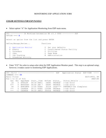
ESP-12S User Manual2.Pin DescriptionsThere are altogether 16 pin counts, the definitions of which are described in Table 2 below.Figure 2 ESP-12S pinoutTable 2 ESP-12S pin descriptionPin numberPin namefunction1RSTReset module2ADCA/d conversion result. Input voltage range 0 1V, value range: 0 10243ENChip enable pin. Active high4GPIO16GPIO16; can be used to wake up the chipset from deep sleep mode5GPIO14GPIO14; HSPI CLK6GPIO12GPIO12; HSPI MISO7GPIO13GPIO13; HSPI MOSI; UART0 CTS8VCC3.3V power supply (VDD)5
ESP-12S User Manual2.1.GND9GND10GPIO15GPIO15; MTDO; HSPICS; UART0 RTS11GPIO2GPIO2; UART1 TXD12GPIO0GPIO013GPIO4GPIO414GPIO5GPIO515RXD0UART0 RXD; GPIO316TXD0UART0 TXD; GPIO1InterfacesTable 3InterfaceDescriptions of InterfacesDescriptionPin NameIO12(MISO),HSPIIO13(MOSI)SPI Flash , display screen, and MCU can be connected using IO13(B)Currently the PWM interface has four channels, but users can extendthe channels according to their own needs. PWM interface can beused to control LED lights, buzzers, relays, electronic machines, andso on.The functionality of Infrared remote control interface can beIR RemoteIO14(IR T),ControlIO5(IR R)implemented via software programming. NEC coding, modulation,and demodulation are used by this interface. The frequency ofmodulated carrier signal is 38KHz.ESP8266EX integrates a 10-bit analog ADC. It can be used to test theADCTOUTpower supply voltage of VDD3P3 (Pin3 and Pin4) and the inputpower voltage of TOUT (Pin 6). However, these two functions cannotbe used simultaneously. This interface is typically used in sensor6
ESP-12S User Manualproducts.I2CIO14(SCL),I2C interface can be used to connect external sensor products andIO2(SDA)display screens, etc.Devices with UART interfaces can be connected with the module.Downloading: U0TXD U0RXD or GPIO2 3(CTS)Communicating: UART0: U0TXD, U0RXD, MTDO (U0RTS), MTCK(U0CTS)Debugging: UART1 TXD (GPIO2) can be used to print debugginginformation.By default, UART0 will output some printed information when thedevice is powered on and is booting up. If this issue exerts influenceUART1:IO2(TXD)on some specific applications, users can exchange the inner pins ofUART when initializing, that is to say, exchange U0TXD, U0RXD withU0RTS, U0CTS.I2S Input:IO12 (I2SI DATA) ;IO13 (I2SI BCK );IO14 (I2SI WS);I2SI2S Output::I2S interface is mainly used for collecting, processing, andtransmission of audio data.IO15 (I2SO BCK );IO3 (I2SO DATA);IO2 (I2SO WS ).7
ESP-12S User Manual2.2.Pin ModeTable 4 Pin ModeModeGPIO15UARTlowFlash BootlowGPIO0GPIO2lowhighhighhigh2.3. Antenna interfaceESP-12S Modules through the IPEX interface to connect to external antenna.The antenna must be in line with the 802.11g/802.11b IEEE standard, and the antenna parameters are shown inthe following table:Table 5 Antenna parametersRatingFrequency rangeImpedanceValue2.4 2.4825GHz50Ω8
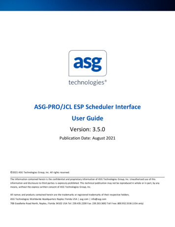
ESP-12S User Manual3.Package information and OEM installation methodThe external size of theESP-12S WiFi module is 16mm*17mm*3mm, as is illustrated in Figure 4 below:Figure 3 Top View of ESP-07s WiFi ModuleFigure 4 Dimensions of ESP-12S WiFi ModuleTable 5 Dimensions of ESP-12S WiFi ModuleLength16mmwidth17mmHeight3 mmPAD Size(Bottom)Pin Pitch1 mm x 1.2 mm2mm9
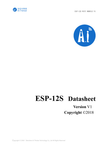
ESP-12S User Manual3.1.Package informationESP-12S use a half hole patch package, Module PCB Footprint shown in the following figure:Figure 5 Module PCB Footprint3.2.OEM installation mathodUsing ESP-12S module Please reference in front of the package information in the Layout on the main board forOEM factory .Please pay more attention Module's direction and the antenna close to the edge of board is better ,theComponents and layout should not be on the bottom of antenna then soldering the module.when the module besoldering can not in the environment of high temperature ,We recommend the reflow soldering temperature curves isshown in figure 6:Figure 6Recommend reflow soldering temperature curves10
ESP-12S User Manual4. Absolute Maximum RatingsTable 6 Absolute Maximum RatingsRatingConditionValueUnitStorage Temperature-40 to 125 Maximum Soldering Temperature260 3.0 to 3.6VSupply VoltageIPC/JEDEC J-STD-0204.1Recommended Operating ConditionsTable 7 Recommended Operating ConditionsOperating ConditionSymbolOperating TemperatureSupply voltageVDDMinTypMaxUnit-4020125 3.03.33.6V4.2.AT commend Testing1.Hardware connectionAs shown in Figure 7, ESP-12S via a USB to TTL Tool connected to the computer, software tool through the serialport on the computer can be AT instruction testFigure 7 ESP-12S connect with computer11
ESP-12S User Manual4.3.AT commendEspressif AT instruction set functions and methods of useAT commands set is divided into: Basic AT commands, WiFi related AT commands, TCP / IP AT4.3.1.AT Command DescriptionTable 8 Each Command set contains four types of AT commands.Notes:1. Not all AT Command has four commands.2. [] default value, not required or may not appear3. String values require double quotation marks, for example:AT CWSAP "ESP756290","21030826",1,44. Baudrate 1152005. AT Commands has to be capitalized, and end with "/r/n"4.3.2.Basic AT Command SetThe ESP8266 wireless WiFi modules can be driven via the serial interface using the standard ATcommands. Here is a list of some basic AT commands that can be used.12
ESP-12S User ManualTable9 basic AT commandsAT – Test AT startupThe type of this command is "executed". It's used to test the setup function of your wireless WiFimodule.13
ESP-12S User ManualAT RST – Restart moduleThe type of this command is "executed". It’s used to restart the module.AT GMR – View version infoThis AT command is used to check the version of AT commands and SDK that you are using, the typeof which is "executed".AT GSLP – Enter deep-sleep modeThis command is used to invoke the deep-sleep mode of the module, the type of which is "set". Aminor adjustment has to be made before the module enter this deep sleep mode, i.e., connectXPD DCDC with EXT RSTB via 0R.14
ESP-12S User ManualATE – AT commands echoThis command ATE is an AT trigger command echo. It means that entered commands can be echoedback to the sender when ATE command is used. Two parameters are possible. The command returns"OK" in normal cases and "ERROR" when a parameter other than 0 or 1 was specified.AT RESTORE – Factory resetThis command is used to reset all parameters saved in flash (according to appendix), restore thefactory default settings of the module. The chip will be restarted when this command is executed.Detailed instruction test, please refer to the Esp8266 AT Instruction Set, can be downloaded to shun official website。15
ESP-12S User Manual 12. 4.3.AT commend . Espressif. AT instruction set functions and methods of use . AT commands set is divided into: Basic AT commands, WiFi related AT commands, TCP / IP AT . 4.3.1.AT Command Description . Table 8 Each Command set contains four types of AT commands. Notes: 1. Not all AT Command has four commands. 2.