Transcription
PCC (TS)
Thank you for choosing L&T Electrical & Automation (E&A)as your supplier of Low Voltage Switchgear and giving usthe opportunity to serve you. Please read this manualcarefully for proper installation, safe, easy and efficientoperation.Reference list of drawings (RLD)Single line drawingsGeneral Arrangement (GA) drawingsMaster bill of materials (MBOM)Scheme drawingsOnly authorized and qualified personnel should be allowedto work on the switchgear. An authorized and qualifiedoperator is a person having detailed information aboutinstallation and commissioning of switchgear or speciallytrained for the maintenance of the switchgear and fullyaware of the hazards caused by unsafe operation. Anoperator should also have basic knowledge of First Aid.The information herein is general for all specifications, partof which may not be applicable for specific applications orvariants. Refer the following 'as built' documents for anyparticular installation:In case of any conflict between this manual and drawingsavailable with you, the drawings shall take precedence.For additional information or clarification please sendyour queries to AtYourService@Lntebg.com for quickresolution.All our switchgear undergo rigorous testing and qualitychecks at our factory. However, we recommend verificationand testing at site, especially after storage.Following symbols have been used in this manual to indicate varying levels of danger:Warning-Highly dangerous- can cause death or serious injuryCaution-Dangerous- can cause injuries or damage the switchgear.Type TS PCC
CONTENTS1 INTRODUCTION12 CONSTRUCTION2TECHNICAL DATA4PANEL CONFIGURATIONS6BUSBARS AND DROPPERS10AUXILIARY BUSBARS113 HANDLING & TRANSPORTATION12RECEIVING13HANDLING134 STORAGE165 GENERAL SAFETY186 INSTALLATION20TYPICAL ARRANGEMENTS21TOOLS22SITE PREPARATION22ERECTION22FLOOR PREPARATION & PANEL MOUNTING22CONNECTION OF TRANSPORT UNITS & BUSBARS24CONNECTION OF EARTHBARS25-PCC (TS) - PCC (TS)25-PCC (TS) - MCC (TX)25POWER CABLE26CONTROL CABLES28INTERPANEL WIRING28Type TS PCC
CONTENTSINSTALLATION OF LOOSE MATERIAL29-METERING AND CONTROL DEVICES29-ACB29-CONTROL TRANSFORMERS31INSTALLING AN EXTENSION PANEL7 SITE TESTING3234TESTING SWITCHBOARDS35TESTING CURRENT TRANSFORMERS35TESTING POTENTIAL TRANSFORMERS35TESTING METERS AND TRANSDUCERS35TESTING RELAYS36TESTING CONTROL CIRCUITS368 PRE-ENERGIZING ECAUTIONS47-ROUTINE CHECKS47-ACB MAINTENANCE48-REMOVAL OF ACB49-REMOVAL OF DOORS499 TROUBLE SHOOTING5010 RECOMMENDATIONS5311 LIST OF FIGURES5412 LIST OF TABLES54Type TS PCC
INTRODUCTIONIMPORTANT NOTEOnly the Specific written Technical Instructions supplied by E&A must be used. Our products must only be commissioned,operated, serviced, repaired or decommissioned in accounts with Technical Instructions which have been supplied by themanufacturer. Non Compliance with this instruction may result in serious damage to the product and its associated items, aswell as health hazard or mortal danger.WARRANTYOur products are subjected to factory inspection and testing according to the applicable standards and provisions.The correct function and the service life of the switchgear are influenced greatly by compliance with the installation,commissioning and operating conditions stipulated in this manual.Non-compliance with these provisions may compromise warranty claims.Any local provision which does not contradict the specifications of this document, especially as regards safety for personneland buildings, must be complied with.E&A cannot be held liable for the possible consequences of:Non-compliance with the provisions contained in this manual, which refer to international regulations.Non-compliance with the instructions of the suppliers of cables and connecting accessories as regards application andinstallation.Any aggressive climate conditions (humidity, pollution etc.) prevailing in the immediate environment of switchgear notsuitable to this effect or not protected accordingly.This manual does not contain any instructions regarding the mechanical lock-outs to be performed. The work described isperformed on de-energized (on installation) or mechanically locked - out (decommissioned) switchgear.Type TS PCC1
CONSTRUCTIONType TS PCC2
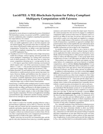
CONSTRUCTION1. Power Control Centre type TS is a free-standing andfloor mounting switchboard suitable for indoorinstallation.AuxiliaryBusbars2. The frames are of bolted construction with welded baseand top.HorizontalWirewayUnitCompartment3. Each vertical panel is divided into distinct zones forbusbars, droppers, auxiliary busbars, unit compartment,power cabling and control terminals Figure 2.4. The unit compartments houses main equipment like AirCircuit Breakers, Fuse Switches, Moulded Case CircuitBreakers and associated auxiliary equipment.5. For optimum utilization of panel space, compartmenthave variable heights with a minimum of 220 mm.Aux.Compartment6. Up to two tiers of ACB can be mounted in TS panel.7. Compartment doors are provided with twin-actiondoor fasteners (Cam Lock). While closing, the fastenerengages with the frame in the first quarter turn, and inthe second quarter turn, it pulls the door towards theframe. This ensures compression of gasket between doorand frame. The fasteners are operated by special key.TerminalChamberFigure 2 - Door Open view8. The rear doors are hinged and provided with twin actiondoor fasteners.Figure 1 - Typical PCC panelType TS PCC3
CONSTRUCTIONTECHNICAL DATAE&A s TS range of Low Voltage Power Control Centers comply with IEC 61439-Part1 & 2. TS is designed to enhancesafety of the users. Its modular construction facilitates logistics, installation, commissioning and maintenance.DesignationStandards and specificationsInsulation characteristicsElectricalcharacteristicsVoltage ratingsPower Control Centre (PCC)Type TSPower Switchgear and Controlgear (PSC)AssembliesIEC 61439 - 2, BS EN 61439 - 2Testing under conditions of arcing due tointernal faultsIEC 61641Clearance 20 mmCreepage distances 20 mmOvervoltage categoryII / III / IVPollution degree3Field conditionInhomogeneous (non-uniform)Rated operational voltage (Ue)up to 690 VRated insulation voltage (Ui)1000 VRated impulse withstand voltage (Uimp)6 / 8 / 12 kVRated frquency (fn)50 / 60 HzTable No. 1To increase cabling area, add-on-chambers (AOCs) with a depth of 300 mm are provided on the rear side.Type TS PCC4
CONSTRUCTIONMain Horizontal busbars:Rated current (InA)up to 6300 ARated peak withstand current (Ipk)up to 220 kARated short-time withstand current (Icw)up to 100 kA, 1sup to 50 kA, 3sCurrent ratingsElectricalcharacteristicsVertical Distribution busbars for PCC:Rated current (InA)up to 2000 ARated peak withstand current (Ipk)up to 220 kARated short-time withstand current (Icw)up to 100 kA, 1sup to 50 kA, 3sInternal Arcfault conditionsRated conditional short-circuit current (Icc)up to 80 kAPermissible conditional short-circuit currentup to 100 kADuration500 msAcceptance Criteria as per IEC 616411 to 7In accrodance with IEC 60529:Degree ofProtectionMechanicalImpactForms faceTreatmentResitance toCorrosionPlasticcomponentsExternalIP 30 / IP 40 / IP 42 / IP 54InternalIP 2X / IP XXB / IP 4X / IP XXDas per IEC 62262IK 08 / IK 09 / IK 10as per IEC 61439 - 2Form 1 to Form 4as per BS EN 61439 - 2upto Form 4, Type 6Height (mm)2200, 2400Width (mm)700, 900, 1000 (PCC)Depth (mm)600, 1000, 1100 (PCC)StructureAlu-zinc / powder coated / paintedInternal ComponentsAlu-zinc / powder coated / paintedExternal Componentspowder coated / paintedDamp heat cycling testIEC 60068-2-30Salt mist testIEC 60068-2-11Flame retardant, self-extinguishing,Halogen-freeIEC 60695-2-10, IEC 60695-2-11Table No. 1Type TS PCC5
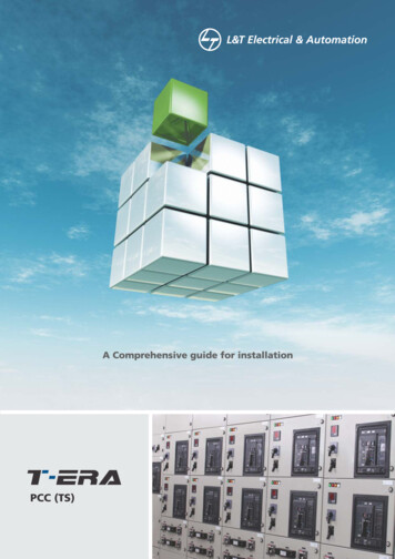
CONSTRUCTIONPANEL CONFIGURATION(Depth 600mm)*F*F*F3004406008002200 / 21530155.25*F800Power cable areaControl cable area*F*Dimensions do not include doorsFront Side(All dimensions are in mm)Type TS PCC6
CONSTRUCTIONPANEL CONFIGURATION(Depth 1000mm)*F*F*F*F30044060080010002200 / 15*F295615*F295295615155.25*F8001000Power cable areaControl cable area*F*Dimensions do not include doorsFront Side(All dimensions are in mm)Type TS PCC7
CONSTRUCTIONPANEL CONFIGURATION(Depth 1100mm)*F*F*F*F30044060080010002200 / 15*F295715*F29529571530155.258001000Power cable areaControl cable area*F*Dimensions do not include doorsFront Side(All dimensions are in mm)Type TS PCC8
CONSTRUCTIONPANEL CONFIGURATION(Depth 1260mm)*F*F*F*F30044060080010002200 / 75*F295875*F295295875155.25*F8001000Power cable areaControl cable area*F*Dimensions do not include doorsFront Side(All dimensions are in mm)Type TS PCC9
CONSTRUCTIONBUSBARS AND DROPPERS1. Bus-bars are arranged in a Double deck Figure 3. Theyare available in two variations depending on the rating /busbar material (Aluminum or Copper), - Double decknon-interleaved (DDNIL) arrangementwith phasesequence of B-Y R-N -Double deck interleaved (DDIL)arrangement with phase sequence of B-Y-R-B-Y-R-N with50% neutral ( B-Y-R-B-Y-R-N-N in 100% neutral).2. In case of DDIL arrangement the busbars are interleaved.The links connecting ACB to busbars or droppers areconnected to both packets of busbars and droppers. Tofacilitate cable / duct termination, cable / duct links arenot interleaved. They are stacked together for eachphase.Figure 3 - Double Deck arrangement of busbarsFigure 4 - Busbar SupportsNNRYBRDDIL systemFigure 5 - Four links supportYBNRYBDDNIL systemFigure 6 - Two links supportType TS PCC 10
CONSTRUCTIONAUXILIARY BUSBARSAuxiliary busbars are located in the top front chamber of thepanel and segregated from main busbars by a metallicpartition.A horizontal wireway is provided immediately below theauxiliary busbar for interpanel wiring. Shipping sectionterminals if required are mounted in the horizontal wirewayFigure 7.Shipping section terminalsHorizontal wirewayFigure 7 - Aux bus chamberUp to 12 Auxiliary busbars of 63 A rating can be provided. The Auxiliary busbars are mounted in Nylon Housing to providesegregation and prevent accidental contact.Block1 stblock2 ndblockSr. No.123456789101112DescriptionSpace Heater - PhSpace Heater - N240 / 110 AC V Aux supply - Ph / Clean Earth Bus240 / 110 AC V Aux supply - N110 V DC Aux Bus supply - ve110 V DC Aux Bus supply - -veAnnunciation Test BusAnnunciation Accept BusAnnunciation Reset BusAnnunciation Alarm BusClean Earth BusConfigurableWire WayTable No. 2* The above table is indicative and can be configured based on actual requirements.Type TS PCC 11
HANDLING ANDTRANSPORTATIONType TS PCC 12
HANDLING AND TRANSPORTATIONReceiving:Handling:On receipt of the PCCs at site:TUs can be handled either by fork-lift or overhead cranesin an upright position depending on where they have tobe placed. Care should be taken to see that the TUs don ttopple during transportation.Verify the following details on packing case Figure 8 :Item no.:Description of material:Package No.:Avoid tilting of TUs (Panels).Gross weight:Dimensions:While transporting the panel using a forklift, ensure thatthe distance between the legs of the forklift and groundis at least 12 cm.Volumes:Limit the speed of the forklift to 10 kmph.Storage of goods:Use both legs of the forklift.Net weight:Special instruction:Verify the quantity of TUs & loose material as per thepacking list.If switchgear are to be installed at higher elevations, shiftthem from the unloading spot through the openingplanned in the building for this purpose. This should be onewith all safety precations and strict supervision by trainedpersonnel.If the packing case is damaged, open the cases andinspect the PCCs. Report any damage or loss ofcomponents to the transport/carrier and lodge a claimwith the insurance agency or inform your nearestE&A office.Figure 9 - Positioning of TU on truckFigure 8 - Packing case DetailsType TS PCC 13
HANDLING AND TRANSPORTATIONIn case of handling by lifting crane,Suspend ropes from the hook and pass them under thewooden pallet at the bottom of the TU.Center of gravity indicators and chain marks areprovided on the TU as shown in Figure11.Use PP (Poly-propylene) ropes of minimum 1 diameterfor this purpose. Choose the diameter of the ropeaccording to the weight of the TU which is mentionedin GA your drawing.Verify that the route from the unloading spot to theerection spot has free access.Unload the TUs after reaching the unloading spot.Figure 11 - Chain marks on packed TUsooooooooWe recommend handling and shifting panelsin packed condition only.DO NOT MOVE THE PANEL BY INSERTING ACROWBAR BELOW THE BASE FRAME. Thismay cause damage to the base frame.In case the TU is unpacked before reaching the site, usethe lifting channel provided at the top of the panel foreasy transportation Figure 9 & Figure 10 .Figure 10 - Lifting anglesWhile unloading a TU, ensure that the remainingTUs are placed securely on the truck and are notin danger of toppling over.If rollers are used for placing the sections on the foundation,retain the base plank to avoid damage to the baseframe.Ensure that:The load of the TU is equally distributed by using allthe lifting angle holes.The sling of the crane is in good condition.The TU does not tilt or topple during transit.Type TS PCC 14
RECEIPT AND HANDLINGTo facilitate transportation and handling, the Power ControlCentre (PCC) TS is split into multiple sections/ transport units(TUs). Each section is wrapped with a HDPE (High DensityPolyethylene) cover and packed in a wooden case. To arriveat the approximate overall dimensions of thepacking cases, add 300 mm to the dimensions of therespective section.List of equipments and special tools for site erectionand assemblyCrane and truck for equipment shifting.Slings and ropes - As per requirement.Rolling pipes - 10 Nos.Channels - 10 m.Crowbars - 4 Nos.Welding machines - 1 No.Spanner sets - 1 Set.(Ring & Open spanner size 13mm, 17mm, 19mm, and24mm. Box or pipe spanner 13mm.)For safe handling lifting angle (θ) should be greaterthan 45 Figure 9 & Figure 10.Type TS PCC 15
STORAGEType TS PCC 16
STORAGEIf the PCC is to be commissioned at a later date, thefollowing precautions should be taken.OUTDOOR STORAGE SHOULD BE AVOIDED. Store allcases indoors, in a clean, dry and well ventilated placewhere seepage of water and condensation does notoccur.Maintain a minimum temperature of - 5 C and humidityof less than 50%.If civil construction is being carried out in the vicinity,ensure that the PCC is completely protected fromdebrisand dust.Keep proper tags / markings on the panels for easytraceability.Unpacking of the TUs at site is preferable. In case itbecomes necessary to unpack the TUs during storage,make sure that packing of all the internal componentse.g. covers on the relays and meters mounted on thedoor etc remain intact (Highlighted in the figurebelow). Also inspect the PCC for scratches, if any.Please use paint supplied with the loose materials totouch up scratch marks.The switchboard should be stored indoorswith proper ventilation. Moist / corrosiveenvironments may affect the metallic partsand cause their insulation to deteriorate.Type TS PCC 17
GENERAL SAFETYType TS PCC 18
GENERAL SAFETYWhile shifting the panel from storage point to erection site:Use a lifting crane to load the panel on to the truck.Ensure that TUs are placed in a vertical position on thetruck.Tie the TUs properly to prevent unwanted movement.Refer the previous section for TU handling instructions.(Page No.12).Personnel handling the equipment must be skilled andauthorised to handle the intended voltage level.All working personnel must be aware of safetypractices.Safety shoes should be worn so as to avoid the risk ofany electric shock while at work.Gloves and goggles should be used while working in theproximity of hot and hazardous materials to avoid bodilyinjury.Appropriate tools and instruments should be used asstated on page no. 16 for precise workmanship.Suitable Caution labels and sign boards should beerected at the time of installation and testing of boardsas a mark of caution.Type TS PCC 19
INSTALLATIONType TS PCC 20
INSTALLATIONTypical arrangements2200 mm1000 mmPower Control CentreFigure 12 - Typical arrangementsType TS PCC 21
INSTALLATION5. Place the first TU over the base channel frames erectedin the floor concrete by the civil contractor. Checkcorrectness of leveling ( 1 mm tolerance per meter isallowed) and alignment of panels & proceed as perGeneral Arrangement (GA) Drawings.TOOLSTorque wrenchBush RatchetHydraulic jack6. Maintain clearances as mentioned in GA drawings.Provide sufficient space on all sides of the panel forpersonnel to work conveniently.Rubber malletClampsFigure13 - ToolsFLOOR PREPARATION AND PANEL MOUNTINGSITE PREPARATIONPanel can be mounted on the floor either by bolting or tackwelding with the ISMC Base Channel / Base Frame.1. The installation site must be clean and the surface even.The panel is provided with integral 50 mm base Frame madeof 3mm sheet metal.Use shims if the floor is uneven. An uneven foundationmay cause misalignment of sections, bus-bars andhinged doors of the unit.2. Walls and ceilings must be plastered with paintingcompleted.3. Doors and windows must be installed.4. Openings in the floor, wall and ceiling for cables,conductor pipes, bars and ventilation must be inaccordance with the construction drawings provided.Follow the steps listed below to mount the panel.Grout / weld the ISMC Base Channel / Base Frame on theinserts in the floor. Make sure that it is perfectly leveled.Place the panel on to the ISMC Base Channel / BaseFrame.Refer Figure 14 for placing the panel on to the ISMC Basechannel / Base frame5. Supporting brackets, beams, enclosures and foundationframes must be assembled and painted.6. lf necessary, braces appropriate to the basicdimensions of the switchgear installation with crossstruts corresponding to the panels must be assembled.Suitable indoor conditions must be maintainedand necessary emergency exits must be providedin the switchgear room.Excessive temperature fluctuations and highhumidity should be prevented.Condensation should be prevented.If the plant s atmosphere is likely to containexcessive steam or reactive gases comprisingsulphur or chlorine, ensure that the Switchboardis placed in a separate pressurized room.Panel 1Panel 2Panel 3ISMC Base Channel/BaseFigure 14 - Panel Mounting onISMC Base Channel / Base FrameERECTION1. After TUs have reached the installation site, unpack theTUs and move the packing material to its allocatedarea.Tack-weld or bolt the panel with the ISMC BaseChannel / Base Frame.When bolting the panel, drill the required holes in theISMC Base Channel/Base Frame, so that it matches withthe holes provided in the integral base Frame.2. Check if all components are in place as per yourdrawings (MBOM) and the packing list.3. Vertical sections should be shifted sequentially into theinstallation site for ease of installation.4. The TUs must be carried in an upright position to avoidthe risk of toppling. Refer the section Floor preparation &panel mounting.Type TS PCC 22
INSTALLATIONA typical drawing is shown below for reference:FRONTA typical drawing for the ISMC base Frame with the holespunched is shown below along with the coupling of theintegral base frame to the ISMC Frame: Figure 15.Coupling of ISMC Frame to the integralIntegralBase FrameISMC Base FrameFoundationholesTo access the foundation holes given on the integralbase Frame, open the front & rear doors and removethe gland plate.Bolt or tack-weld the panel to the ISMC Base Channel/Base Frame.Figure15 - Integral Base FramePlease ask for project specific drawings if you arebolting the panel to an ISMC base channel/frame.If you decide tp tack-weld the panels to the basechannels/frames, such drawings are not requiredFigure 14.Figure16 - ISMC Base FrameEnsure that the board is properly aligned whilebolting / tack-welding.Type TS PCC 23
INSTALLATIONCONNECTION OF TRANSPORT UNITS AND BUSBARS1. For access to the horizontal busbars, remove top platesand hoods (if provided) by removing all the boltsprovided on the top Figure 16.2. Remove the fish plates provided on the right side of thebusbar to connect it with subsequent TUs placedsequentially.3. Clean the fishplates with a wire brush. Wipe them with asoft, dry cloth and then immediately apply contactgrease on them. Hindustan Petroleum, MPL (EXXON) /Petroleum Jelly J. P. grade contact grease or equivalentis recommended.4. Bolt adjacent TUs together - holes are provided in thegasketted side pillar. This should be done before joiningthe busbars.5. Join horizontal bus bars using the fishplates as shown inFigure17.Figure 18 - Busbar joining6. Tighten all electrical connections, except Hole-lessHorizontal busbar joints (HBB) ,with a torque wrench tothe torque values as mentioned in table no.3. For Holeless HBB joints, torque values to be as mentioned in table3A Figure18.Figure 19 - Tightning of Busbar jointsSize of bolt Torque in m.kgFigure 17 - Top plateEnsure bus bars are properly aligned so that thereis no strain on any of the support insulators.KgfmThread(Bolt size)NmNormal High Tensile Normal High TensileBoltBoltBoltBolt(Grade: 4.8) (Grade: 8.8) (Grade: 4.8) (Grade: 63.7419/18Table No. 3For aluminum bus bar system normal torque to be applied even if the bolt is HT. HT torque values are applicableonly for hole less bus bar joints.Type TS PCC 24
INSTALLATIONThread(Bolt size)Cumulative thickensof conductor at joint(T) mmTorque(kgfm)T 205.75 0.2520 T 356.25 0.25T 356.75 0.25M12High TensileBolt(Grade 8.8)SocketNo.(mm)18/19Table No. 3AEARTHBARFISHPLATE7. Join the auxiliary busbars by joining the auxbus fish plateprovided for the same in the left side TU Figure 19.Figure 21 - PCC - PCC Earthbar CouplingPCC (TS)-MCC (TX)1. Open the rear door of the PCC.2. Remove the fishplate provided at the end of horizontalearthbar at the bottom.Figure 20 - Auxbus joiningCONNECTION OF EARTHBARS3. Connect the fishplate with the already extended MCCearthbar.4. Tighten the connection with a torque wrench to thetorque values as mentioned in Table No.3.PCC (TS) - PCC (TS)1. For single front panels, open the rear door of the panel toaccess the horizontal earthbar.2. In case of a back to back arrangement, open the cablealley to access horizontal earthbar.3. Remove the fishplate provided on left hand side TU toconnect it with subsequent TUs placed sequentially.4. Join the earth bars using the fishplate provided and checkcorrectness.5. Tighten the connection with a torque wrench to thetorque values as mentioned in Table no. 3.PCC HORIZONTALEARTHBARMCC HORIZONTALEARTHBARFigure 22 - PCC - MCC Earthbar CouplingType TS PCC 25
INSTALLATIONPower cableterminalPOWER CABLE:TOP CABLE ENTRY1. Remove the top plate Figure 24.2. Punch the required holes on the top plate depending oncable size and gland type.3. Follow the instruction given under cable termination.Figure 25 - Power cable terminalsPunch the required holes on the gland plate depending oncable size and gland type Figure 27.Figure 23 - Top plateBOTTOM CABLE ENTRYRemove the gland plate-provided at the rear bottom side ofthe panel in two sections Figure 25.Figure 26 - Power cable terminals bottom cable entry12*RCable termination:1. Remove insulation from cable ends without damagingthe conductor strands.Power cableterminals2. In case sector shape conductors are used, form theconductor using a circular forming die.3. Refer following section for terminating power cables.3. Clean the conductor and coat immediately withinhibiting compound like petroleum jelly.Gland Plate4. Crimp the lug terminals properly as improper crimpingmay result in higher temperature rise at the joints.5. Coat the lug barrel with an inhibiting compound frominside.Forming should be done prior to cleaning andapplying inhibiting compound.Figure 24 - Power Cable terminalsType TS PCC 26
INSTALLATION6. Use lugs with serrated barrels for crimping aluminiumconductors (Serration increases the pull strength aftercrimping. It also cuts through the oxide film, if any,formed on the conductor).7. Use proper crimping dies, as recommended by the lugmanufacturer. For aluminium conductors, use ring orhexagonal dies. Ensure that the die surfaces meetduring crimping. Incomplete crimping will result inhigher temperature rise at the joints.BOTTOM BUSDUCT ENTRYRemove the gland plate provided at rear bottom side ofthe feeder.Connect the flats of the busduct with the links at theend of the busduct link using the flexibles Figure 29.8. Ensure proper clamping of cables on the glands andcableclamps to avoid weight of cables acting directly onthe termination.9. Block all the unused holes Figure 27.10. Ensure no free hanging of cable wire.11. All cable wires should be supported appropriately &rigidly at required no. of locations. Ensure cables are at asafe distance (min 50 mm) from live parts.Duct linkBUSDUCT TERMINATION:TOP BUSDUCT ENTRYRemove the top plate of the incomer or outgoingfeeder.Bus ductterminationConnect the flats of the busduct with the links at theend of the busduct riser using the flexibles Figure28.Figure 28 - Bottom Busduct terminationBus ductterminationIn case Busduct flats and links are of differentmaterial, use bimettalic flexibles to joint thebusduct flats and links.Figure 27 - Top Busduct terminationType TS PCC 27
INSTALLATIONCONTROL CABLES:Interpanel wiring1. Remove the gland plate / base plate.1. Wiring is through the horizontal wire-way at the topalong the auxiliary bus.2. Punch the required holes on the gland plate / base platedepending on cable size and gland type.3. Route the wires through the holes punched in to thebase plate and terminate the cables in the terminalblock provided at the bottom of the panel as per theschemes.Use of copper wire is recommended.Ensure that the connection of the wire is as perthe scheme drawing provided.2. For wiring, separate terminals are provided in the lefthand side of the right most TU which are named XS-YY(X - terminal no. and YY - panel no. (01, 02, 03 etc.)). Thewire bunch to be connected to these terminals is in theleft-hand side transport unit. The wires have ferrules withthe terminal no. and should be connected their respectiveterminals. The no. of terminals and no. of wires to beto be connected are equal.For example, consider the panels and transport units shownin the sketch. The transport unit (TU) consists of panel1F and 2F, while TU-2 consists of panel 3F and 4F. Theterminals named 1,2,3. -XS03 are mounted in panel 3Fas shown in the figure. The mounted terminals areconnected to their respective equipment in panels 3F and4F. The wires going from TU-1 to TU-2 are bunched and keptwith panel 2F. The wire which is to be connected to terminal1 of panel 3F will have a ferrule marked 1XS03 at the end ofit and will be kept in e bunch tobe connectedhavingcorrespondingferrules marked1,2,3.XS03Figure 30 - Interpanel WiringShipping sectionterminalsTerminal BlockHorizontal wirewayBase plate/ gland plateFigure 29 - Control Cable terminalsType TS PCC 28
INSTALLATIONInstallation of loose material:Metering and control devices:Unpack the metering and control devices (like metersand relays) if they were sent as separate packages.Position the device in the apt cut-out or base plateprovided.Wire them as per the scheme drawing provided.Refer to the device leaflet for further details about thedevice.Carry out the settings of magnitude and time delay (ifany) for the installed protective and control devices asshown in scheme drawing and MBOM (Master Bill ofMaterials).Place the terminal covers properly to adhere to statedingress protection (IP) level.ACBUnpack the ACB properly to avoid damaging it usingcrowbar Figure 32.Open the ACB compartment door using the camlockkey provided.Rack out the cradle using the racking handle.If cradle movement is not smooth, apply contact grease.Also check for the free movement of safety shutters.Put the ACB on the cradle with the help of ACB liftingtruck Figure 33.Note that ACB lifting truck will be supplied only if asked bythe customers.In case if you dont have ACB lifting truck please contactthe sales team for ordering the same or email toAtYourService@Intebg.comCheck alignment of operating handles for all switches.While dispatching the switchboard, secondaries of allcurrent transformers are shorted. Remove these shortingwhile connecting relays/meters and store themseparately.Ensure again that all doors are closed and no connectionis left loose.Figure 32 - ACB lifting truckFigure 31 - Unpacked ACBType TS PCC 29
INSTALLATIONLoading in panel:1. Pull-out the Cradle Rails & ensure that position indicationshows DISCONNECTED2. Load the ACB using crane. Even bottom trolley can beused.4. Gently push the ACB to DISCONNECTED position andclose the Panel door.If equipped with Rating Error Preventor, Cradle will notaccept ACB of different rating.5. Keeping the OFF button pressed, open the RackingShutter. In case panel door is open, also gently defeatRacking Interlock.3. Ensure that ACB rests correctly in 2 slots on either sideof cradle rail.6. Rack-in the ACB to Service position. Two almost-simultaneous Click sounds confirm CONNECTEDposition.Improper loading of ACB may lead to personalinjury and damage to product.Excessive forceful racking-in beyond Connectedposition lead to product damage.Type TS PCC 30
INSTALLATIONControl Transformers1. Unpack the Control Transformer.2. Open the compartment door in which the ControlTransformer is to be installed.3. Bolt the Contr
Type TS PCC 5 CONSTRUCTION Table No. 1 Main Horizontal busbars: Rated current (I nA) up to 6300 A Rated peak withstand current (I pk) up to 220 kA Rated short-time withstand current (I cw) up to 100 kA, 1s up to 50 kA, 3s Vertical Distribution busbars for PCC: Rated current (I nA) up to 2000 A Rated peak withstand current (I pk) up to 220 kA