Transcription
ICND1 -100-101 Study Guide (CCENT)SECTION I (6%) – Purpose & Function of Various Network Devices (Routers, Switches, Bridges,Hubs)1.1 – Recognize Purpose & Functions of Various Network Devices (Routers, Switches, Bridges, Hubs)a. Repeater1) Purpose: unintelligent Layer 1 device to resolve attenuation (media distance constraints)2) Function: 2-port device that regenerates signals to span greater than media distances allow;doesn’t alter or interpret signal just listens to signal & reproduces itb. Hub1) Purpose: multiport Layer 1 repeater to resolve attenuation issues (media distance constraints)2) Function: Advg – extends networks like repeaters, allows connection of more than 2 devices(than repeaters), central point for cabling; Disadvg – creates more collisions (sharedbandwidth), greater congestion, no traffic control (filtering), & only Half-Duplex (one-directionalcommunication)c. Bridges1) Purpose: intelligent Layer 2 (Data Link) control2) Function: joins/extends LAN segments, regenerates signals, reduces collisions, learn & filtertraffic based on MAC Address; Half-Duplexa) Floods Frames – sends out every port except port was received on; unknown unicast nodestination MAC address in Frame; Broadcasts; Multicastsb) Forwards Frames – concept of MAC Address Tables (learns source MAC & Port the devicesconnected to it)c) Filter – based off MAC Address Table entries, may drop Frames depending on source &destination addresses in a Framed. Switches1) Purpose: multiport bridges with additional features; intelligent Layer 22) Function: Full-Duplex (bi-directional communication at same time); faster than Bridges (Gb);switching done in hardware3) Switching Methods Flood, Forward, Filter (see the Bridge Section above)4) Benefitsa) Each port micro-segments LAN providing dedicated bandwidth to the connected deviceb) Allows multiple simultaneous conversations between devices on different portsc) Full-Duplex support, in effect doubling bandwidth available to connected deviced) Support for rate (speed) adaptation for devices configured with different speeds5) Memory Types:a) ROM – bootstrap executed upon bootup; POST; hard-coded onto Switch motherboardb) NVRAM – non-volatile RAM; stores startup config permanently upon rebootc) Flash – NVRAM type that stores IOS image; retained upon shutdownd) RAM – active memory; running configuration, committed to NVRAM upon using “copy” cmd
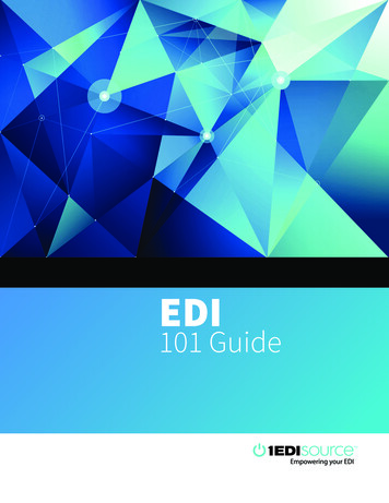
e. Routers1) Purpose: enables data to transfer from one IP network to a different IP network2) Function: allows “internal” networks to communicate with “external” networks (NAT)3) Bootup Process:a) Run POST1. Configuration Register (0x21xx) is checked; 0x2102 Default; 0x2142 Pwd changeb) Find IOS in Flash (if none found, loads from ROM)c) Load IOS to RAMd) Find the (Startup) Config in NVRAM (if none found, broadcast to a TFTP server for Config)e) Load (Startup) Config to RAM4) Router Files:1.2 – Select Components Required to Meet a Given Network Specificationa. This is relative; I would probably think in terms of the capabilities of each device, for examplewhat creates or segments Broadcast vs Collision Domainsb. Where is a given device used (i.e. which Layer uses Repeaters, Hubs, Bridges, Switches, Routers)c. Think of device function what it does or is capable of doing with network traffic1.3 – Identify Common Applications & Their Impact on the Networka. DNS – TCP/UDP 53; Domain Name Service, translating Hostnames to IPs1) Hosts/devices send DNS Requests to resolve a hostname to an IP Address2) Once hostname is resolved to an IP Address, the client begins TCP connection process
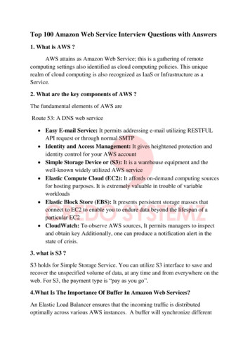
b. DHCP – UDP 67/68; Dynamic Host Configuration Protocol, assigns IPs & other options dynamicallyc. FTP – TCP 20/21; File Transfer Protocold. HTTP (WWW) – TCP 80; Hyper-Text Transfer Protocol, web server access1) Web clients send HTTP GET Requests for web page files; the web server sends an HTTP OKresponse2) Ex. http://www.certskills.com/ICND1 http protocol used; www.certskills.com hostname;ICND1 web page namee. POP3 – TCP 110; Post Office Protocol, email accessf. SMTP – TCP 25; Simple Mail Transfer Protocol, email accessg. SNMP – UDP 161; Simple Network Management Protocol, device monitoring & managementh. SSH – TCP 22; Secure Shell, encrypted remote management (using PuTTy e.g.)i. SSL – TCP 443; HTTPS, encrypted web server accessj. Telnet – TCP 23; unencrypted remote management (using PuTTy e.g.)k. TFTP – UDP 69; basic version of FTPl. QoS – Quality of Service; 4 QoS characteristics/components:1) Bandwidth – volume of bits/second2) Delay – amount of time it takes one IP Packet to flow from sender to receiver3) Jitter – variation in delay4) Loss - % of Packets discarded by network before they reach the receiver/destinationAPPLICATION CATEGORYWeb Browsing (Interactive)VoIPVideo SMediumLowLow1.4 – Describe the Purpose & Basic Operation of Protocols in the OSI & TCP/IP ModelsOSI MODELa. Application Layer (L7):1) Interface between network & application software; user authentication; provides services toapplications but is NOT the application itself2) Data Unit Data3) Protocols SMTP, POP3 – email; SSH – Secure Shell & Telnet for remote console access (Putty,WinSCP); DNS – resolves Hostname to IP & vice versa; FTP – file transfer protocol4) Workstations, Servers, Firewallsb. Presentation Layer (L6):1) Defines data format & encryption; this Layer no longer in use
2) Data Unit Data3) Protocols ASCII, JPEG, Binary, EBCDIC4) Workstations, Serversc. Session Layer (L5):1) How to start & end conversations between endpoints; manages the point-to-pointcommunication; this Layer no longer in use2) Data Unit Data3) Protocols NETBIOS4) Workstations, Serversd. Transport Layer (L4):1) Provides flow control & error recovery to prevent data loss; focuses on data delivery to otherendpoints/devices2) Data Unit Segment3) Protocols TCP, UDP; also uses Port #’s (e.g. 21 [ftp], 22[ssh], 25[smtp], 53[dns], 80[http],139[ldap], 443[https], etc.)4) Connection-Oriented (TCP) – uses acknowledgment & flow control, sets up a virtual circuit;Connectionless-Oriented (UDP) – unreliable, uses best effort; fast; relatively no overhead; novirtual circuit; e.g. Radio, Streaming Video, TVa) Three-Way Handshake SYN SYN, ACK ACK1. Sender sends a Segment incorporated with a Sequence Number2. The Receiver responds with an ACK with its own Sequence Number & what the Sender’snext Sequence Number should be3. The Sender responds with a Segment with the data stream’s next Sequence Numberb) Positive Acknowledgment & Retransmission (PAR) – continued guaranteed communicationafter the 3-Way Handshake process1. Sender starts a timer when sending a Segment; retransmits Segment if timer expires beforean ACK is received from the Receiver2. Sender keeps record of all Segments sent & expects an ACK for each one sent3. Receiver sends an ACK after each Segment indicating the expected next Sequence NumberSegmentc) Sliding Window – process of a Receiver telling Sender to slow its Segment transfer rate if it(Receiver) is getting more Segment ‘hits’ than it can handle1. Number of Segments a Sender can send in a transmission before Receiver sends an ACK; ifReceiver isn’t busy, the window size can be large; more congestion smaller window size2. Windows size is included in Segment headers and can change during conversation lifespan5) Routers, Firewallse. Network Layer (L3):1) Routing (forwarding), path determination, & logical addressing2) Data Unit Packet3) Protocols IP, ICMP4) Routers, Layer-3 Switchesf. Data Link Layer (L2):1) Provides media access control (MAC Address), error detection & assembles bits from frames &vice versa; rules to determine when a device can transmit data; defines formats of Frame
headers/trailers2) Data Unit Frame3) Protocols Ethernet, Serial, PPP, ATM, DOCSIS, DSL4) Switches, Bridges, WAP (Wireless Access Point), Cable/DSL Modemsg. Physical Layer (L1):1) Sends & receives bits and provides specification of voltage, wire speed, & cable pin-outs; bits(on/off electrical pulses); physical characteristics of transmission medium (connectors, pins, etc)2) Data Unit Bits3) Protocols Glass (Fiber), Copper (CAT-3/5/6), RJ454) Hubs, Repeaters, Cables, Radio WavesEncapsulation – process of lower level OSI or TCP/IP Model layers encapsulating data unit created atthe upper layer levels; then transformed to 1s/0s (electrical impulses/voltages) at the physical layerTCP/IP MODELa. Applicationb. Transportc. Internetd. Network Interface1.5 – Predict the Data Flow Between Two Hosts Across a Networka. Begin with 4.1 a. below – Packet Forwarding process; otherwise, thinking through the belowbriefly discussed items should provide you with info needed to work through network traffic flowb. Think about what happens from source Host to target Host, name resolution, MAC identification(ARP), to Subnet identification (Route lookup), to VLAN accessibility, to Internet accessc. Think of traffic flow in terms of protocol process; e.g. how is ARP handled on an Internetwork (i.e.LAN vs remote Subnet)
d. How are Frames handled by PCs, Switches, Routers; Encapsulation & De-encapsulation1.6 – Identify the Appropriate Media, Cables, Ports, & Connectors to Connect Cisco Network Devices toOther Network Devices & Hosts in a LANa. Common Media Cable Types (Name, Notation, Cable, IEEE Notation, Speed, Length):LANEthernet Cable Type/SpeedMediaIEEE NotationLength10BASE-T / 10MbpsCAT3 or better (2-pair) 802.3100m100BASE-T / 100MbpsCAT5-UTP (2-pair)802.3u100m1000BASE-T / 1000MbpsCAT5e/6-UTP (4-pair)802.3ab100m1000BASE-LX or SXMultimode Fiber802.3z550m1000BASE-LXSingle-Mode Fiber802.3z5km10GBASE-TCAT6a-UTP802.3an100mCODE: T Twisted Pair ; X Fiber ; L Long Wave Length ; S Short Wave Lengthb. Deprecated/Less Used Cables:1) Thicknet; 10BASE-5; RG-8; 802.3; 10Mb; 500m2) Thinnet (“cheaper net”); CATV coax, 10BASE-2; RG-58; 802.3; 10Mb; 185mWAN3) Leased Lines – uses 2 pairs of crossover in Full Duplexa) Names Circuit; Serial (Link); Point-to-Point; T1; WAN Linkb) Customer Site CPE (Customer Premise Equipment) Host, Switch, Router w/Serial Interface,CSU/DSU (channel service unit/data service unit); Leased Line (LL) Telco Switch LL CPEon Customer 'other side' (CSU/DSU Router 2 LAN Switch 2 Host)c) Speeds – slower multiples of 64Kbps; faster multiples of 1.54Mbpsd) Layer 2 Protocols Used – HDLC (High-Level Data Link Control) and PPP (Point-to-PointProtocol)1. HDLC – control correct delivery of data over a physical WAN link; HDLC Frame Fields Flag,Address, Control, FCS; NOTE: Cisco adds a Type fielde) Benefits simple, widely available, private, high quality; Negatives high cost, lengthy install4) Ethernet – uses Fibera) CPE Fiber Ethernet Link Service Provider (SP) Ethernet Switch SP Point-of-Presence(POP) Ethernet (Fiber) WAN SP POP Ethernet Switch Fiber Ethernet Link CPEb) EoMPLS – Ethernet over Multiprotocol Label Switching; does not use a serial interface at CPE1. PC Switch Router w/Ethernet Interface EoMPLS (Fiber) Link R2 w/EI SW2 PC2c. Connectors1) RJ45 (8P89C) – used with Copper cables2) SFP (small form-factor pluggable) or GBIC (gigabit interface converter) – used by Fiber cables3) ST – Straight tip Connector for Fiber/Optical; MMF4) SC – Subscriber Connector for Fiber/Optical; MMF or SMF5) LC – Lucent Connector for Fiber/Optical; most common fiber connector
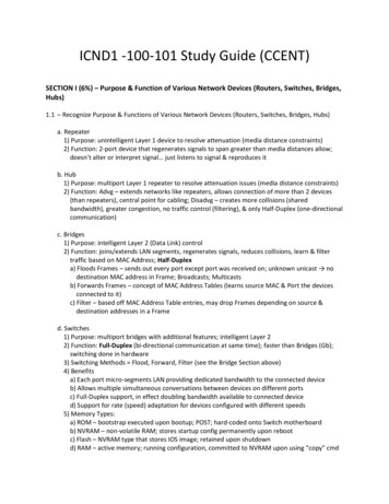
d. Straight-Through Cable – pins are connected to same pins on each side of connection (1 1, 2 2, 3 3, 6 6)1) Connect PC to Switch or Hub2) Connect Router to Switch or Hub3) Basically, when connecting “computers” (Workstations, Servers, Routers) to a Switch, Hub, orWAPe. Crossover Cable – pins are crossed across sides (1 3, 2 6)1) Connect PC to PC2) Connect Switch to Switch3) Connect Router to Router4) Connect PC to Router5) Connect Hub to Hubf. Rollover Cable – pins are exact opposite from pins 1-8 ( 1 8, 2 7, 3 6, 4 5)1) Connect directly to CONSOLE Port of Router or Switch from PCTABLE TO SUMMARIZE DEVICE CONNECTIVITY REQUIREMENTSPIN/WIRING STANDARD (T568B) FOR STRAIGHT-THROUGH & EXAMPLE
g. Ethernet (802.3) – defines WIRED LAN technology only, not wireless1) Ethernet Address Typesa) Unicast – one workstation to one workstation communicationb) Broadcast – one workstation to all other workstations communicationc) Multicast – one workstation to a select group of workstations communication(Destination MAC Address Field starts with 0100.5exx.xxxx.xxxx)2) Ethernet Frame Contents:Preamble7 bytesSFD1 byteDestMACAddr6 bytesSourceMACAddr6 bytesType (IPv4/6, 0800/86DD)2 bytesDATA46-1500bytesFCS4 bytesa) Start Frame Delimiter (SFD) – signifies the next byte begins Destination MACb) Dest/Source MAC1. MAC Address – 3 bytes (8bits) OUI assigned by IEEE, 3 bytes Vendor-assignedc) Frame Check Sequence (FCS) – method for receiving NIC to determine if Frame hadtransmission errorsh. EMI – electromagnetic interference1) Crosstalk: NEXT (near-end), FEXT (far-end), AXT (alien)i. Attenuation – signal loses strength over distanceSECTION II (21%) – LAN Switching Technologies2.1 – Determine the Technology & Media Access Control Method for Ethernet Networksa. CSMA/CD – Carrier Sense Multiple Access with Collision Detection – CSMA devices using sharedmedium (wire) for communication, analogous to landline home phone Half-Duplex –sending traffic in one direction at a time [e.g. analogous to a one-way bridge]);legacy Hub-based or “Ethernet bus” networks1) Workstations listen to the wire2) If no one is sending data, data is sent by a workstation
3) If multiple workstations are sending at the same time, there will be a frame collision, causing avoltage spike on the “wire” (10volt spike)4) Damaged Frames from colliding workstations will be discarded5) Workstations will then send out a “jamming signal” to prevent other workstations fromtransmitting frame
ICND1 -100-101 Study Guide (CCENT) SECTION I (6%) – Purpose & Function of Various Network Devices (Routers, Switches, Bridges, Hubs) 1.1 – Recognize Purpose & Functions of Various Network Devices (Routers, Switches, Bridges, Hubs)