Transcription
ATI Compliant Deburring Blade(Models 0)Product ManualDocument #: 9610-50-1030Engineered Products for Robotic ProductivityPinnacle Park 1031 Goodworth Drive Apex, NC 27539 Tel: 1.919.772.0115 Fax: 1.919.772.8259 www.ati‑ia.com
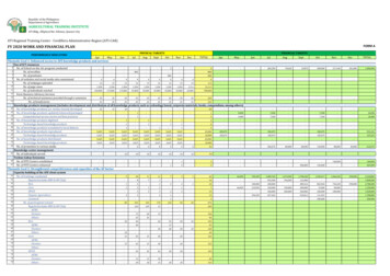
Manual, Compliant Deburring BladeDocument #9610-50-1030‑05ForewordCAUTION: This manual describes the function, application, and safety considerations of thisproduct. This manual must be read and understood before any attempt is made to install oroperate this product. Failure to do so may result in personnel injury and/or damage to equipment.Information contained in this document is the property of ATI Industrial Automation, Inc (ATI) and shall not bereproduced in whole or in part without prior written approval of ATI. The information herein is subject to change withoutnotice. This manual is periodically revised to reflect and incorporate changes made to the product.The information contained herein is confidential and reserved exclusively for the customers and authorized agents of ATIIndustrial Automation and may not be divulged to any third party without prior written consent from ATI. No warrantyincluding implied warranties is made with regard to accuracy of this document or fitness of this device for a particularapplication. ATI Industrial Automation shall not be liable for any errors contained in this document or for any incidentalor consequential damages caused thereby. ATI Industrial Automation also reserves the right to make changes to thismanual at any time without prior notice.ATI assumes no responsibility for any errors or omissions in this document. Copyright (2021) by ATI Industrial Automation. All rights reserved.How to reach us:Sale, Service and Information about ATI products:ATI Industrial Automation1031 Goodworth DriveApex, NC 27539 USAwww.ati‑ia.comTel: 1.919.772.0115Fax: 1.919.772.8259Application EngineeringTel: 1.919.772.0115Fax: 1.919.772.8259E‑mail: applicationsengineers@ati‑ia.comPinnacle Park 1031 Goodworth Drive Apex, NC 27539 Tel: 1.919.772.0115 Fax: 1.919.772.8259 www.ati‑ia.com2
Manual, Compliant Deburring BladeDocument #9610-50-1030‑05Table of ContentsForeword. 2Glossary. 51.2.3.4.5.Safety. 61.1Explanation of Notifications. 61.2General Safety Guidelines. 61.3Safety Precautions. 7Product Overview. 82.1ATC Collet System. 92.2Tool Stand. 92.3Technical Description. 102.3.1Environmental Limitations. 102.3.2Compliance Unit Performance. 11Installation of the Compliance Device. 123.1Transportation and Protection during Transportation. 123.2Inspection of Condition When Delivered. 123.3Unpacking and Handling. 123.4Storage and Preventive Maintenance during Storage. 123.5Axial Mounting Installation. 133.6ATC Tool Stand Installation. 133.7Pneumatics. 14Operation. 154.1Working Environment. 154.2Normal Operation. 164.3Programming for ATC Tool Stand. 174.4Installing the Customer Supplied Blade Holder in the Manual Collet. 184.5Removing the Customer Supplied Blade Holder in the Manual Collet. 194.6Locking and Unlocking Single Axis Compliance. 20Preventive Maintenance. 215.1Pneumatics. 215.2Lubrication. 215.3Blade Inspection. 21Pinnacle Park 1031 Goodworth Drive Apex, NC 27539 Tel: 919.772.0115 Fax: 919.772.8259 www.ati‑ia.com3
Manual, Compliant Deburring BladeDocument #9610-50-1030‑056.Troubleshooting and Service Procedures. 226.1Troubleshooting. 226.2Service Procedures. 236.2.1Replacement of Bit Holders in ATC Tool Stand. 237.Serviceable Parts. 248.Specifications. 249.Drawings. 259.19630‑50‑CDB‑PNEUMATIC. 2510. Terms and Conditions. 27Pinnacle Park 1031 Goodworth Drive Apex, NC 27539 Tel: 919.772.0115 Fax: 919.772.8259 www.ati‑ia.com4
Manual, Compliant Deburring BladeDocument #9610-50-1030‑05GlossaryTermDefinitionACAxially Compliant.Air FilterDevice for removing contamination from air supply lines. Typically refers to removal ofparticulates.ATCAuto Tool ChangerBladeCutting tool used to remove burrs from the work piece.BurrAny unwanted, raised protrusion on the work piece.CDBCompliant Deburring BladeCoalescing FilterDevice designed to remove liquid aerosols from the supply air lines.ColletGripping device used to hold cutting tools in the spindle.ComplianceThe ability of the spindle to passively move in response to protrusions on ordeviations of the work piece.DeburrTo remove the burrs from (a piece of machined work).Positive StopThe tool has contacted a physical limitation and can no longer move.RCRadially Compliant.Rear HousingRear cover to the main housing. This body includes a connection port for thecompliance air supply.RegulatorDevice used to set and control the supplied air pressure to lower acceptable levels.Solenoid ValveElectrically controlled device for switching air supplies on and off.Tool StandStorage location for tools while not in use.Pinnacle Park 1031 Goodworth Drive Apex, NC 27539 Tel: 1.919.772.0115 Fax: 1.919.772.8259 www.ati‑ia.com5
Manual, Compliant Deburring BladeDocument #9610-50-1030‑051. SafetyThe safety section describes general safety guidelines to be followed with this product, explanations of thenotifications found in this manual, and safety precautions that apply to the product. More specific notifications areimbedded within the sections of the manual (where they apply).1.1Explanation of NotificationsThe following notifications are specific to the product(s) covered by this manual. It is expected that the userheed all notifications from the robot manufacturer and/or the manufacturers of other components used in theinstallation.DANGER: Notification of information or instructions that if not followed will result indeath or serious injury. The notification provides information about the nature of thehazardous situation, the consequences of not avoiding the hazard, and the method foravoiding the situation.WARNING: Notification of information or instructions that if not followed could resultin death or serious injury. The notification provides information about the nature of thehazardous situation, the consequences of not avoiding the hazard, and the method foravoiding the situation.CAUTION: Notification of information or instructions that if not followed could resultin moderate injury or will cause damage to equipment. The notification providesinformation about the nature of the hazardous situation, the consequences of notavoiding the hazard, and the method for avoiding the situation.NOTICE: Notification of specific information or instructions about maintaining, operating,installing, or setting up the product that if not followed could result in damage to equipment. Thenotification can emphasize, but is not limited to: specific grease types, best operating practices,and maintenance tips.1.2General Safety GuidelinesPrior to purchase, installation, and operation of the CDB, the customer should first read and understand theoperating procedures and information described in this manual. Never use the CDB tool for any purposes,or in any ways, not explicitly described in this manual. Follow installation instructions and pneumaticconnections as described in this manual.All pneumatic fittings and tubing must be capable of withstanding the repetitive motions of the applicationwithout failing. The routing of pneumatic lines must minimize the possibility of stress/strain, kinking,rupture, etc. Failure of critical pneumatic lines to function properly may result in equipment damage.Pinnacle Park 1031 Goodworth Drive Apex, NC 27539 Tel: 1.919.772.0115 Fax: 1.919.772.8259 www.ati‑ia.com6
Manual, Compliant Deburring BladeDocument #9610-50-1030‑051.3Safety PrecautionsWARNING: Never operate the CDB tool without wearing eye protection. Flyingdebris can cause injury. Always use eye protection while working in the neighborhoodof the CDB tool.CAUTION: Do not use spare parts other than original ATI spare parts except forconsumables. Use of spare parts not supplied by ATI can damage equipment and voidthe warranty. Always use original ATI serviceable parts.CAUTION: Never be present near the CDB tool while it is in operation. Flying debriscan cause injury. If it is necessary to approach the CDB tool while in motion, standbehind appropriate clear guards or similar windows. Provide a barrier to prohibit peoplefrom approaching the CDB tool.CAUTION: Do not perform maintenance or repair on the CDB tool unless the toolis safely supported or placed in the tool stand and air has been turned off. Injury orequipment damage can occur with tool not placed in a tool stand and air remainingon. Place the tool safely in the tool stand and turn off the air before performingmaintenance or repair on the CDB tool.Pinnacle Park 1031 Goodworth Drive Apex, NC 27539 Tel: 1.919.772.0115 Fax: 1.919.772.8259 www.ati‑ia.com7
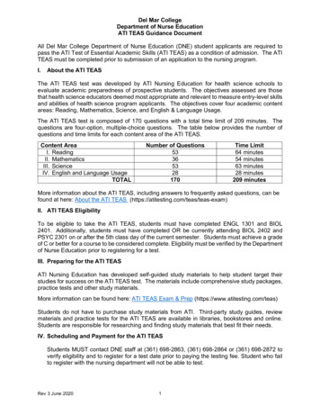
Manual, Compliant Deburring BladeDocument #9610-50-1030‑052. Product OverviewThe Compliant Deburring Blade (CDB) is especially suited for removal of parting lines and flash from parts. TheCDB’s Auto Tool Changer (ATC) allows it to be used in a wide variety of applications without human interaction.The CDB’s pneumatically controlled, articulated compliance allows the blade to follow the part profile andcompensate for surface irregularities while maintaining a constant force. As a result, high feed rates with uniformquality in any orientation is achievable. The tool requires no oil.When the customer supplies air pressure to the compliance air fitting, the tool activates a compliance feature (orcomplies) for consistent deburring on irregular part patterns. The CDB utilizes standard industrial blades that allowfor adaptation to changing assembly lines and part requirements.Axially mount the CDB tool to the customer robot. The customer can mount the tapered flange of the CDB toan interface plate that adapts to a robot. The customer can purchase custom interface plates from ATI (refer toSection 3.5—Axial Mounting Installation and https://www.ati‑ia.com/Products/deburr/deburring cdb main.aspxfor more information)The CDB can be manually locked to single axis compliance using the single axis lockout (refer to Section 4.6—Locking and Unlocking Single Axis Compliance for more information)Figure 2.1—CDB ToolAxial Mounting FlangeCompliance Air Supply Fitting4 mm / 5/32” Push to ConnectCDB BodySingle Axis LockoutATC Collet(2) ATC Air Supply Fitting3 mm / 1/8” Push to ConnectPinnacle Park 1031 Goodworth Drive Apex, NC 27539 Tel: 1.919.772.0115 Fax: 1.919.772.8259 www.ati‑ia.com8
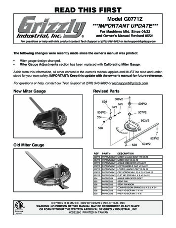
Manual, Compliant Deburring BladeDocument #9610-50-1030‑052.1ATC Collet SystemThe ATC’s pneumatically controlled collet system allows the tool holder to be locked and unlocked to theCDB without human interaction, once a program is in place. The ATC’s pneumatically controlled tool standallows the tool holder to be locked and unlocked to the storage location As a result, faster tool changeoversare achievable. The ATC requires no oil.2.2Tool StandA tool stand is a pneumatic controlled locking and unlocking storage location for tool holders.Figure 2.2—Tool StandT-nutLatchMounting Fastener(2) 3 mm / 1/8” Push to Connect FittingPinnacle Park 1031 Goodworth Drive Apex, NC 27539 Tel: 1.919.772.0115 Fax: 1.919.772.8259 www.ati‑ia.com9
Manual, Compliant Deburring BladeDocument #9610-50-1030‑052.3Technical DescriptionThe technical overview of the product is in the following tables and graphs. For additional technicalspecifications, refer to Section 8—Specifications.2.3.1 Environmental Limitations2.3.1.1 OperationTable 2.1—OperationInstallationpositionMounted to robot by means of the axial mountingflange. Refer to Section 3.5—Axial MountingInstallation. The flange is specific to each type of robot.This optional flange is normally supplied by ATI in ablank form suitable for customer modification.Mounted to a table or stand by means of the benchadapter (the robot is carrying the work piece).The tool requires the following: Clean, dry, filtered, non‑lubricated air.A coalescing filter and filter elements rated5 micron or better. The compliance (centering) air must be suppliedfrom a regulated source between1‑4.1 bar (15‑60 psi). The lock/unlock air must be supplied from aregulated source of 4.1 bar (60 psi). The lock/unlock air must be supplied from a regulatedsource of 4.1 bar (60 psi). Tubing should besemi‑rigid polyethylene material (80R durometer).Soft rubber tubing will not secure in push toconnect fitting.Utilities2.3.1.2 StorageTable 2.2—StorageStore the tool in its case and in a dry place.ConditionsWhen not in use, keep the unit in its case if possible.Consult Section 3.4—Storage and PreventiveMaintenance during Storage of this manual.Pinnacle Park 1031 Goodworth Drive Apex, NC 27539 Tel: 1.919.772.0115 Fax: 1.919.772.8259 www.ati‑ia.com10
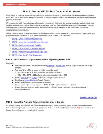
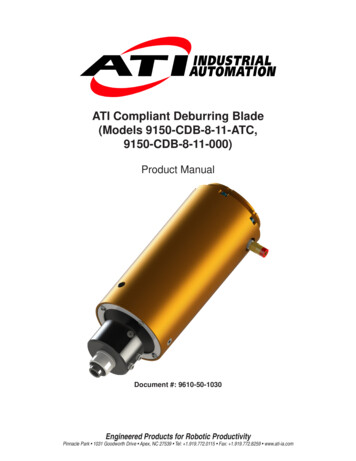
Manual, Compliant Deburring BladeDocument #9610-50-1030‑052.3.2 Compliance Unit PerformanceThe graphs in Figure 2.3 and Figure 2.4 illustrates the variation of compliance force with appliedair pressure in the vertical orientation with the collet pointed toward the ground. Measurementsmay vary from one product to another and should only be treated as nominal.The actual force characteristics depend on mounting orientation and condition of the unit.Compliance pressure is also dependent upon the material of the work piece, type of blade tool, andthe amount of material that is removed.Figure 2.3—Radial Compliance Force (Measured at the Collet)Supply Pressure vs Average RadialCompliance ForceRadial Compliance Force (lbs)18161412108642051015202530354045505560Supply Pressure (psi)Figure 2.4—Axial Compliance Force (Measured at the Tool Tip)Supply Pressure vs Axial Compliance Force16.00Axial Compliance Force 2030405060Supply Pressure (psi)Pinnacle Park 1031 Goodworth Drive Apex, NC 27539 Tel: 1.919.772.0115 Fax: 1.919.772.8259 www.ati‑ia.com11
Manual, Compliant Deburring BladeDocument #9610-50-1030‑053. Installation of the Compliance DeviceThe CDB tool is delivered fully assembled. Optional equipment such as mounting plates and additional customersupplied tool holders are separate.3.1Transportation and Protection during TransportationThe CDB tool is packaged in a case designed to secure and protect it during transportation. Always use thecase when transporting the CDB tool in order to minimize the risk of damage.3.2Inspection of Condition When DeliveredUpon receipt, the following should be checked: Delivery in accordance with freight documents Packaging in good conditionIf there is damage to any of the packaging, or if any of the goods have been exposed to abnormal handling,unpack those parts that may have been damaged for a closer inspection. If necessary, notify ATI forassistance in evaluation of the product condition.3.3Unpacking and HandlingThe CDB tool should always be placed inside the accompanying case during transportation,storing and handling.Pneumatic lines are attached, bundled, and must be strain‑relieved in a manner that allows for freedom ofmovement during operation.3.4Storage and Preventive Maintenance during StorageStore the CDB tool in its case when it is not in use. The CDB tool should also be stored in a dry place.For long‑term storage, the CDB tool should be thoroughly cleaned of any burrs or debris. It should not bedisassembled. Place the CDB tool inside a sealed, plastic bag inside the case.Pinnacle Park 1031 Goodworth Drive Apex, NC 27539 Tel: 1.919.772.0115 Fax: 1.919.772.8259 www.ati‑ia.com12
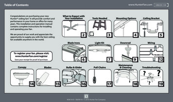
Manual, Compliant Deburring BladeDocument #9610-50-1030‑053.5Axial Mounting InstallationA blank interface plate is also available to allow axial mounting off the rear of the CDB housing. Thisplate may be modified by the system integrator or by the owner/user of the CDB. ATI can provide custominterface plates and adapters upon request.Figure 3.1—Axial InstallationBlank InterfacePlateAxial Mounting Flangeon Rear HousingAssemblyClamping Collar(2) M5 SocketHead Cap Screw3.6ATC Tool Stand InstallationA tool stand is designed to attach to a customer supplied extruded aluminum rail.Tools required: 6 mm hex key1. Install the ATC tool stand system:a. Remove the end cap from the customer supplied extruded aluminum rail.b.Slide the ATC tool stand into the slot on the rail.c.Using a 6 mm hex key, tighten the M8 socket head cap screw in the ATC tool stand to89 in‑lbs (10 Nm).d.Install end cap onto the customer supplied extruded aluminum rail.e.Install the (2) 3 mm push‑to‑connect air lines to the ATC tool stand.Figure 3.2—Axial InstallationCustomer SuppliedExtruded Aluminum RailWith End CapsInstall End CapSlide ATC Tool StandInto Slot in RailPinnacle Park 1031 Goodworth Drive Apex, NC 27539 Tel: 1.919.772.0115 Fax: 1.919.772.8259 www.ati‑ia.com13
Manual, Compliant Deburring BladeDocument #9610-50-1030‑053.7PneumaticsConnect the air lines as shown in Section 9.1—9630‑50‑CDB‑PNEUMATIC.WARNING: All pneumatic fittings and tubing must be capable of withstanding therepetitive motions of the application without failing. The routing of pneumatic lines mustminimize the possibility of over stressing, pullout, or kinking the lines. Failure to doso can cause some critical pneumatic lines not to function properly and may result indamage to equipment.The air supply should be dry, filtered, and free of oil. A coalescing filter (ATI Part # 9005‑50‑6160 orequivalent) with elements rated for 5 micron or better is required.A self‑relieving regulator (ATI Part # 9005‑50‑6164, or equivalent) is used to supply the compliance(centering) mechanism. This pressure corresponds to the side force on the blade. Because very little air flowis required for the compliance mechanism, a smaller valve can be used (consult the valve and regulatorsupplier’s literature when selecting these components).Solenoid valves are actuated from the robot or program logic controller by means of a digital output signal.The lock/unlock for the tool stand must a regulated air supply pressure of 4.1 bar [60 psi].Tubing for compliance should be semi‑rigid polyethylene material (80R durometer). Soft rubber tubing willnot secure easily in the push‑to‑connect fitting.The compliance force, air supply pressure regulator should have a 1‑4.1 bar [15–60 psi] range. When testingfor the proper contact force, start with about 1 bar [15 psi] of pressure and increase the pressure slowly untilthe desired cut is achieved.Pinnacle Park 1031 Goodworth Drive Apex, NC 27539 Tel: 1.919.772.0115 Fax: 1.919.772.8259 www.ati‑ia.com14
Manual, Compliant Deburring BladeDocument #9610-50-1030‑054. OperationFor assistance in programming, starting up, and complete a robotic deburring cell containing a CDB tool referto the following section: The system integrator should be familiar with the task of deburring and have extensiveknowledge about automation applications that incorporate robots.DANGER: Never use the CDB tool for purposes other than robotic deburring. If used in anyother way, serious injury or damage to equipment may occur.WARNING: All personnel, who are involved in operation of the CDB tool, should have athorough understanding of the operating procedures. Failure to follow these procedures orneglecting safety precautions can create hazardous situations that may injure personnel ordamage the deburring installation and the CDB tool.WARNING: Never operate the CDB without wearing eye protection. Flying debris can causeinjury. Always use eye protection while working in the proximity of the CDB tool.CAUTION: Do not use spare parts other than original ATI spare parts except forconsumables. Use of spare parts not supplied by ATI can damage equipment and void thewarranty. Always use original ATI serviceable parts.CAUTION: Never be present near the CDB tool while it is in operation. Flying debriscan cause injury. If it is necessary to approach the CDB tool while in motion, standbehind appropriate protective windows. Provide a barrier to prohibit people fromapproaching the CDB tool.CAUTION: Never use the CDB tool for any purposes, or in any ways, not explicitly describedin this document. Using the CDB tool without fully understanding the installation and operatingprocedures may cause injury to personnel or damage to equipment.4.1Working EnvironmentThe CDB tool should only be used in conjunction with a robot in a secured work cell/chamber.The work cell must be secured by barriers to prohibit personnel from entering the cell. A lockable doorshould be included as a part of the barrier in order to facilitate access to the cell for authorized personnelonly. The barrier could consist partly or fully of clear guards or similar to facilitate observation of thedeburring operations.During system or CDB tool maintenance, make sure the CDB tool and robot are stopped before entering therobot cell. When installing and testing, never be present in the cell when the CDB tool is in operation.Pinnacle Park 1031 Goodworth Drive Apex, NC 27539 Tel: 1.919.772.0115 Fax: 1.919.772.8259 www.ati‑ia.com15
Manual, Compliant Deburring BladeDocument #9610-50-1030‑054.2Normal OperationThe following sections describe the normal operating conditions for CDB.4.2.1 Air QualityThe air supply should be dry, filtered, and free of oil. A coalescing filter with elements rated for 5micron or better is required. The air must be supplied to the ATC collet at between 1‑4.1 bar (15‑60psi) and to the ATC tool stand at 4.1 bar (60 psi).Particulate can block airflow or impede compliance motion. If deburring tools do not receive properair pressure, tool may not re‑center properly. Any water in the system damages the housing andblades.4.2.2 No LubricationThe compliance device cannot have any oil in the air supply. Oil can clog compliance device andlimit compliance range.4.2.3 Blade Selection and MaintenanceCDB accepts industry standard, off the shelf hand deburring blades. As blades near end of theirservice life, surface finish may degrade, necessitating change of blade.Radially loaded blades and scraper tools as well as axially loaded countersink tools are acceptable.Always ensure the ball detent and locking divots on tool holder shaft are aligned radially and that theball is securely seated in the divot. Unsecured blades can cause the shaft to slip, creating hazards foroperators and quality.4.2.4 Deburring Tool Approach Path Should be Slow and at an AngleThe deburring tool should approach the workpiece slowly and at an angle, with ample room forpivoting blade to reorient before beginning each pass.When beginning a deburring pass, try to minimize the initial impact on the work piece by slowlyapproaching the tool at an angle while maintaining a parallel path with the surface.If the tool quickly approaches perpendicularly to the workpiece, the result is gouging andpremature wear of the tool bearings and bur. Additionally, collisions could result and create ahazardous situation for both personnel and equipment.When using pivoting blades, approach from a distance and angle for the blade to catch on theworkpiece edge. Program the robot accurately when the contact holes are geometrically equal to orless than the tool’s pivot radius.Note: some tools are directionally dependent. Before use, always verify the intended direction ofblade operation.4.2.5 Single Axis LoadingWhile using single axis lockout, do not apply radial loads that are perpendicular to the axis of pivot.Always keep the tool pivoting perpendicular to the deburring surface. Loading the tool along the pivotaxis will damage the pivot pins and cause premature failure.4.2.6 Program the Robot to Incorporate 50% Compliance Travel of the ToolProgram the robot to have the tool’s compliance at 50% travel when on the nominal path.As the part’s edge deviates from the perfect path, the bur can use compliance to follow along highand low spots without losing contact or hitting the positive stop and gouging. Do not “bottom out” thecompliance and hit the positive stop.Repeated impacts on the positive stop create slop in the compliance and reduce recenteringrepeatability.Pinnacle Park 1031 Goodworth Drive Apex, NC 27539 Tel: 1.919.772.0115 Fax: 1.919.772.8259 www.ati‑ia.com16
Manual, Compliant Deburring BladeDocument #9610-50-1030‑054.3Programming for ATC Tool StandThe tool stand component of the ATC system uses divots in the tool holder shaft for securing the tool to thetool stand. Due to this the tool holder has to extend further out of the ATC collet. The robot program mustaccommodate for this clearance between the tool stand and collet.When adding additional ATC tool stands, a minimum of 25 mm (1”) is required between tool stands. Referto https://www.ati‑ia.com/Products/deburr/deburring cdb main.aspxFigure 4.1—ProgrammingATC ColletClearance NeededATC Tool StandClearance NeededTool HolderNOTICE: The customer must have familiarity with how to actuate each ATC station in orderto manually place each blade. If plant regulations require all pressurized air is released priorto operator’s entrance into a robot cell, the ATC station can be used in conjunction with aswivel table to rotate ATC stations out of the cell. This ensures that the operators remain in asafe environment while the station is energized. If ATCs are maintained within the robot cell,operators must be able to control them through a 4‑way valve or solenoid, so that the ATC canactuate open, the blade(s) can be replaced, and the ATC is actuated closed. Air lines will needto have check valves installed to ensure the ATC station remains locked, if customer supplied airpressure is lost.1. Always use personal protective equipment (PPE) when in robot cell.2. Use teach mode on the robot pendant to
Pinnacle Park 1031 Goodworth Drive Apex, NC 27539 Tel: 1.919.772.0115 Fax: 1.919.772.8259 www.ati‑ia.com . Industrial Automation and may not be divulged to any third party without prior written consent from ATI. No warranty . . Auto Tool Changer: Blade. Cutting tool used to remove burrs from the work piece. Burr.