Transcription
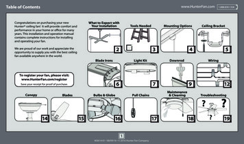
www.HunterFan.comTable of ContentsWhat to Expect withYour InstallationCongratulations on purchasing your newHunter ceiling fan! It will provide comfort andperformance in your home or office for manyyears. This installation and operation manualcontains complete instructions for installingand operating your fan.Tools NeededCeiling Bracket30 inchesPA G EMaintenance& CleaningPull Chains?19PA G E18PA G E1M3614-01 08/09/16 2016 Hunter Fan Company17PA G E16PA G EPA G EPA G E1512Troubleshooting?145Wiring9PA G EBulbs & GlobeDownrod7PA G E6Save your receipt for proof of purchase.4PA G ELight KitTo register your fan, please visit:www.HunterFan.com/registerBlades3PA G EBlade IronsLadderPA G EPA G E2PA G E7 feetWe are proud of our work and appreciate theopportunity to supply you with the best ceilingfan available anywhere in the world.CanopyMounting Options1.888.830.1326
www.HunterFan.comWhat to Expect with Your Installation1.888.830.1326Read and Save These InstructionsThis product conforms to UL Standard 507.If you are unfamiliarwith wiring, use aqualified electrician.WARNINGSw.1 - To reduce the risk of fire, electrical shock, or personalinjury, mount fan directly from building structure and/or anoutlet box marked acceptable for fan support of 70 lbs (31.8 kg)and use the mounting screws provided with the outlet box.30 inchesfrom blade tipto nearest wallor obstructionMust be able tosecure the fan tobuilding structure orfan-rated outlet boxKnow your wiringYou may need afriend to help you.Ceiling angles greaterthan 34 will require anAngled Mounting Kit.See page 4 for details.Check box to seefan weight7 feetfrom bottomedge of bladeto the floorAssess location1Standard Downrod2Shorter Downrodfor ceilings 8-10 feet highfor fans installed close to ceilingw.2 - To avoid possible electrical shock, before installing orservicing your fan, disconnect the power by turning off thecircuit breakers to the outlet box and associated wall switchlocation. If you cannot lock the circuit breakers in the offposition, securely fasten a prominent warning device, such as atag, to the service panel.w.3 - To reduce the risk of fire, electrical shock, or motor damage,use only Hunter Solid State Speed Controls.w.4 - To reduce the risk of personal injury, do not bend the bladebrackets when installing the blade brackets, balancing the blades,or cleaning the fan. Do not insert foreign objects in betweenrotating fan blades.CAUTIONSc.1 - All wiring must be in accordance with national and localelectrical codes ANSI/NFPA 70. If you are unfamiliar with wiring,use a qualified electrician.c.2 - Use only Hunter replacement parts.3Longer Downrodfor ceilings 10 feet or higherThis product may cause interference to radio equipment andshould not be installed near maritime safety communicationsequipment, ships at sea, or other critical navigation orcommunications equipment operating between 0.45-30 MHz.This device complies with Part 18 of the FCC Rules.Assess ceiling angleSelect a downrod length2M3614-01 08/09/16 2016 Hunter Fan Company
www.HunterFan.comTools NeededLadderScrewdriversPliers1.888.830.1326Wire Strippers9/64” Drill Bit(optional)Power Drill(optional)If mounting to a support structure, you will also need these tools.3M3614-01 08/09/16 2016 Hunter Fan CompanyDo not discard the hardware bags or mixparts from different bags. Make note ofthe symbol printed on each hardwarebag. The symbols can be used to identifythe appropriate hardware for each step.
34OCEILINGwww.HunterFan.comMounting OptionsOPTION 1If you have a flat ceiling:1. You will need a longer downrod (sold separately).2. If your ceiling angle is greater than 34 , you willalso need an Angled Mounting Kit (sold tructureOPTION 2If you have an angled ceiling:StandardMountingStyleCeilingOutlet Box(required)Use the three steps below to determine if your ceiling angle is greater than 34 21CeilingOutlet Box(required)AngledMountingStyle334 PLACEFOLDagainst wallon dotted lineGuide TouchesBOTH Ceiling & WallYou need ONLYa LongerDownrod*most commonSLIDEtoward ceilingGuide Touches Wallbut NOT g your fan by a standard downrod (included).1.888.830.1326Use Standard Mountingor Low-Profile Mountingto hang the fan from a flat ceiling.You need BOTHa LongerDownrod &an AngledMounting Kit4M3614-01 08/09/16 2016 Hunter Fan CompanyUse Angled Mountingto hang the fan from avaulted or angled ceiling.
www.HunterFan.comCeiling Bracket1.888.830.1326rweonPrTuOFFFor angled ceilings, pointopening toward peak.Use wood screwsUse machine screws(included) when securing(provided with outletto support structure withbox) when securing toapproved electrical outlet existing ceiling fan-ratedbox. Drill 9/64” pilot holesoutlet box. Make surein support structure to aidit is securely installedin securing ceiling bracket and is acceptable for fanwith hardware found in support of 31.8 kg (70 lbs)thehardware bag.or less.Make sure all four bumpers arestill attached.If you are unable to do this,call Technical Support at1-888-830-1326.Refer to warning w.1 on pg. 25M3614-01 08/09/16 2016 Hunter Fan CompanyTo avoid possible electrical shock, beforeinstalling your fan, disconnect the power byturning off the circuit breakers to the outletbox associated with the wall switch location.
Blade IronsTurn the motor assembly upside down andplace it in one of the holes in the packaging.www.HunterFan.comInstall a blade iron to the blade iron mountingplate using two blade iron assembly screws,found in the hardware bag. Repeat thisprocess to install all five blade irons.6M3614-01 08/09/16 2016 Hunter Fan Company1.888.830.1326
Light Kitwww.HunterFan.com1.888.830.1326Light KitAssemblyScrewPartially install two light kit assemblyscrews, found in thehardware bag,halfway into the motor housing asshown. It does not matter which twoscrew holes you choose.Feed the 9-pin plug connector coming fromthe bottom of the motor housing throughthe center hole in the light kit assembly.Connect it to the plug connector foundin the switch housing area of the light kitassembly. Make sure to line up the coloredmarkings on the connectors.7M3614-01 08/09/16 2016 Hunter Fan CompanyAlign the keyhole slots in the top ofthe light kit assembly with the partiallyinstalled assembly screws. Wrap thekeyhole slots around the screws andtwist counterclockwise.
www.HunterFan.comLight Kit (continued)Insert a third light kit assembly screw,found in thehardware bag, into placeand tighten all three screws securely.Make sure the light kit assembly is securely attached to themotor housing. Failure to properly secure all three assemblyscrews could result in the light fixture falling.Carefully push all switch housingcomponents into the switch housing,then install the switch housing plateusing two light kit assembly screws,found in thehardware bag.8M3614-01 08/09/16 2016 Hunter Fan Company1.888.830.1326
www.HunterFan.comOption 1Downrod1.888.830.1326skip to next pageStandardDownrodfor ceilings 8-10’ highSteps 1-5 to remove standard downrod pipe124Sold SeparatelySlide31098Steps 6-10 to reassemble with new pipe9M3614-01 08/09/16 2016 Hunter Fan Company5SlideOption 3LongerDownrodfor angledceilings orceilings 10’ orhigherShorterDownrodfor fans installedclose to ceilingIncludedOption 2Included(pre-assembled)If you need a different downrod length follow these steps:76
www.HunterFan.comKEEP!(not to scale)8”&3/8”1.888.830.1326STRIPCUTDownrod (continued)!KEEPRemove the pre-installedsetscrew so that the downrodcan be inserted.The wires can be cut, butleave at least 8” extendingfrom the top of thedownrod.Hand tighten the downrod (atleast 4-5 full turns) until it stops.8”Tighten the setscrewwith pliers. DO NOTHAND TIGHTEN.3/8”If the setscrew is not tightenedsecurely, the fan may fall.10M3614-01 08/09/16 2016 Hunter Fan Company
www.HunterFan.comDownrod (continued)Put the wires and downrod through thecanopy. Let the canopy sit loosely on topof the fan.DO NOT PICK THE FAN UP BY THECANOPY OR WIRES. Place the downrodball into the slot in the ceiling bracket.11M3614-01 08/09/16 2016 Hunter Fan Company1.888.830.1326
Wiring: Single Switchwww.HunterFan.com1.888.830.1326Dual SwitchInstructionsHave a single switch?Follow these steps:groUnGroundedWhiteoundingi peStrGrBlueConnect the black wire(ungrounded) from theceiling to the black and theblue wires from the fan.ellowGreen/YConnect the white(grounded) wire fromthe ceiling to the whitewire from the fan.undedGroundedBlackGreen/Yellow StripeConnect the threegrounding wires (green,green/yellow stripe, orbare copper) coming fromthe ceiling, downrod, andhanging bracket.Note: To connect the wires,hold the bare metal leadstogether and place a wireconnector over them, thentwist clockwise until tight.Turn the splices upward and push them carefully back through the hanger bracketinto the outlet box. Spread the wires apart, with the grounded wires on one side ofthe outlet box and the ungrounded wires on the other side of the outlet box.Refer to CAUTION c.1 on pg. 212M3614-01 08/09/16 2016 Hunter Fan Company
Wiring: Dual Switchwww.HunterFan.com1.888.830.1326Have dual switches?Follow these ded(light)BlackingroundedGreen/Yellow StripeConnect the threegrounding wires (green,green/yellow stripe, orbare copper) coming fromthe ceiling, downrod, andhanging bracket.UngConnect the black wire(ungrounded) from theceiling to the blackwire from the fan.ndi peStrConnect the white(grounded) wire fromthe ceiling to the whitewire from the fan.Connect the secondungrounded (light)wire from theceling to the bluewire from the fan.Note: To connect the wires,hold the bare metal leadstogether and place a wireconnector over them, thentwist clockwise until tight.BlueTurn the splices upward and push them carefully back through the hanger bracketinto the outlet box. Spread the wires apart, with the grounded wires on one side ofthe outlet box and the ungrounded wires on the other side of the outlet box.Refer to CAUTION c.1 on pg. 213M3614-01 08/09/16 2016 Hunter Fan Company
www.HunterFan.comCanopyScrewHolesPosition the canopy so that, whenlifted into place, the canopy fits intothe hanging bracket as shown.Lift the canopy into place so thatthe screw holes are aligned.Insert the two canopy screwsfound in thehardware bag.14M3614-01 08/09/16 2016 Hunter Fan Company1.888.830.1326
Bladeswww.HunterFan.comPut each blade washer, found inthehardware bag, onto a blade screw,found in thehardware bag. Then secureeach blade to a blade iron using the bladescrews and washers.15M3614-01 08/09/16 2016 Hunter Fan Company1.888.830.1326
www.HunterFan.comBulbs & GlobeTabNotchInstall a bulb into each of thesockets. When necessary, replacewith bulbs of the same wattage.Position the notches in theouter rim of the globe so theyline up with the tabs on thelight kit assembly.Carefully lift the globe up insidethe light fixture as far as it will go.Rotate the globe in a clockwisedirection until it is held tightly inplace by the three tabs.16M3614-01 08/09/16 2016 Hunter Fan Company1.888.830.1326
www.HunterFan.comPull emove and discard the plasticconnectors from the ends of the shortpull chains coming from the sides of thelight kit assembly.Connect the appropriate pull chainpendant to each of the short chains. Thefan pull chain controls the speed: fromhigh to off. The light pull chain controlsthe light fixture: on and off.17M3614-01 08/09/16 2016 Hunter Fan CompanySee next page for fanoperation instructions.
Maintenance & ReverseSwitchChanging the bulbs - carefullyremove the globe. Unscrew bulbsand replace with bulbs of thesame wattage. Reinstall the globe.Changing the direction ofair flow - carefully remove theglobe and move the reverseswitch to the opposite position.Reinstall the globe.18M3614-01 08/09/16 2016 Hunter Fan CompanyCleaning the fan - use softbrushes or cloths to preventscratching. Cleaning productsmay damage the finishes.
www.HunterFan.comTroubleshootingFan doesn’t workExcessive wobblingNoisy Operation Make sure power switch is on. Tighten all of the blade andblade iron screws until theyare snug. Tighten the blade and bladeiron screws until they are snug. Pull the pull chain to make sureit is on. Push the motor reversing switchfirmly left or right to ensure thatit is engaged. Check the circuit breaker toensure the power is turned on. Make sure the blades spin freely. Check to see if any of theblades are cracked. If so, replaceall of the blades. Turn the power off, supportthe fan carefully, and checkthat the hanger ball isproperly seated. Use the provided balancingkit and instructions to balancethe fan. Turn off power from the circuitbreaker, then loosen the canopyand check all the connectionsaccording to the wiring diagramon page 12-13. Check the plug connection inthe switch housing.19M3614-01 08/09/16 2016 Hunter Fan Company1.888.830.1326
Blade Irons www.HunterFan.com 1.888.830.1326 Turn the motor assembly upside down and place it in one of the holes in the packaging. Install a blade iron to the blade iron mounting plate using two blade iron assembly screws, found in the hardware bag. Repeat this process to install all five blade