Transcription
User’sManualModel EJA110A, EJA120A andEJA130ADifferential Pressure TransmittersIM 01C21B01-01EIM 01C21B01-01EYokogawa Electric Corporation11th Edition
CONTENTSCONTENTS1.INTRODUCTION . 1-1Regarding This Manual . 1-11.1 For Safe Use of Product . 1-11.2 Warranty . 1-21.3 ATEX Documentation . 1-32.HANDLING CAUTIONS . 2-12.12.22.32.42.52.62.72.82.9Model and Specifications Check . 2-1Unpacking . 2-1Storage . 2-1Selecting the Installation Location . 2-2Pressure Connection . 2-2Waterproofing of Cable Conduit Connections . 2-2Restrictions on Use of Radio Transceiver . 2-2Insulation Resistance and Dielectric Strength Test . 2-2Installation of Explosion Protected Type . 2-32.9.1 FM Approval . 2-32.9.2 CSA Certification . 2-52.9.3 IECEx Certification . 2-62.9.4 CENELEC ATEX (KEMA) Certification . 2-82.10 EMC Conformity Standards . 2-112.11 PED (Pressure Equipment Directive) . 2-112.12 Low Voltage Directive . 2-123.COMPONENT NAMES . 3-14.INSTALLATION . 4-14.14.24.34.4Precautions . 4-1Mounting . 4-1Changing the Process Connection . 4-2Swapping the High/Low-pressure Side Connection . 4-34.4.1 Rotating Pressure-detector Section 180 . 4-34.4.2 Using the BRAIN TERMINAL BT200 . 4-34.5 Rotating Transmitter Section . 4-44.6 Changing the Direction of Integral Indicator . 4-45.INSTALLING IMPULSE PIPING . 5-15.1Impulse Piping Installation Precautions . 5-15.1.1 Connecting Impulse Piping to the Transmitter . 5-15.1.2 Routing the Impulse Piping . 5-25.2 Impulse Piping Connection Examples . 5-46.WIRING . 6-16.16.26.3Wiring Precautions . 6-1Selecting the Wiring Materials . 6-1Connections of External Wiring to Terminal Box . 6-16.3.1 Power Supply Wiring Connection . 6-1FD No. IM 01C21B01-01E11th Edition: Oct. 2008(YK)All Rights Reserved, Copyright 1997, Yokogawa Electric CorporationiIM 01C21B01-01E
CONTENTS6.3.2 External Indicator Connection . 6-16.3.3 BRAIN TERMINAL BT200 Connection . 6-16.3.4 Check Meter Connection . 6-26.4 Wiring . 6-26.4.1 Loop Configuration . 6-2(1) General-use Type and Flameproof Type . 6-2(2) Intrinsically Safe Type . 6-26.4.2 Wiring Installation . 6-2(1) General-use Type and Intrinsically Safe Type. 6-2(2) Flameproof Type . 6-36.5 Grounding . 6-36.6 Power Supply Voltage and Load Resistance . 6-37.OPERATION . 7-17.17.27.37.47.5Preparation for Starting Operation . 7-1Zero Point Adjustment . 7-2Starting Operation . 7-3Shutting Down Operation . 7-3Venting or Draining Transmitter Pressure-detector Section . 7-47.5.1 Draining Condensate . 7-47.5.2 Venting Gas . 7-47.6 Setting the Range Using the Range-setting Switch . 7-48.BRAIN TERMINAL BT200 OPERATION . 8-18.1BT200 Operation Precautions . 8-18.1.1 Connecting the BT200 . 8-18.1.2 Conditions of Communication Line . 8-18.2 BT200 Operating Procedures . 8-18.2.1 Key Layout and Screen Display . 8-18.2.2 Operating Key Functions . 8-2(1) Alphanumeric Keys and Shift Keys . 8-2(2) Function Keys . 8-28.2.3 Calling Up Menu Addresses Using the Operating Keys . 8-38.3 Setting Parameters Using the BT200 . 8-48.3.1 Parameter Summary . 8-48.3.2 Parameter Usage and Selection . 8-68.3.3 Setting Parameters . 8-7(1) Tag No. Setup . 8-7(2) Calibration Range Setup . 8-7(3) Damping Time Constant Setup . 8-8(4) Output Mode and Integral Indicator Display Mode Setup . 8-9(5) Output Signal Low Cut Mode Setup . 8-9(6) Change Output Limits . 8-10(7) Integral Indicator Scale Setup . 8-10(8) Unit Setup for Displayed Temperature . 8-11(9) Unit Setup for Displayed Static Pressure . 8-12(10) Operation Mode Setup . 8-12(11) Impulse Line Connection Orientation Setup . 8-12(12) Output Status Display/Setup when a CPU Failure . 8-12(13) Output Status Setup when a Hardware Error Occurs . 8-12(14) Bi-directional Flow Measurement Setup . 8-13(15) Range Change while Applying Actual Inputs . 8-13(16) Zero Point Adjustment . 8-14(17) Span Adjustment . 8-15iiIM 01C21B01-01E
CONTENTS(18) Test Output Setup . 8-16(19) User Memo Fields . 8-168.4 Displaying Data Using the BT200 . 8-178.4.1 Displaying Measured Data . 8-178.4.2 Display Transmitter Model and Specifications . 8-178.5 Self-Diagnostics . 8-178.5.1 Checking for Problems . 8-17(1) Identifying Problems with BT200 . 8-17(2) Checking with Integral Indicator . 8-188.5.2 Errors and Countermeasures . 8-199.MAINTENANCE . 9-19.19.29.39.4Overview . 9-1Calibration Instruments Selection . 9-1Calibration . 9-1Disassembly and Reassembly . 9-39.4.1 Replacing the Integral Indicator . 9-39.4.2 Replacing the CPU Board Assembly . 9-49.4.3 Cleaning and Replacing the Capsule Assembly . 9-59.4.4 Replacing the Process Connector Gaskets . 9-69.5 Troubleshooting . 9-69.5.1 Basic Troubleshooting . 9-69.5.2 Troubleshooting Flow Charts . 9-710. GENERAL SPECIFICATIONS . 10-110.110.210.310.4Standard Specifications . 10-1Model and Suffix Codes . 10-3Optional Specifications . 10-6Dimensions . 10-9Customer Maintenance Parts ListDPharp EJA Series Transmitter Section . CMPL 01C21A01-02EModel EJA110A, EJA120A and EJA130ADifferential Pressure Transmitter . CMPL 01C21B00-01EREVISION RECORDiiiIM 01C21B01-01E
1. INTRODUCTION1.INTRODUCTION The following safety symbol marks are used in thismanual:Thank you for purchasing the DPharp electronicpressure transmitter.The DPharp Pressure Transmitters are preciselycalibrated at the factory before shipment. To ensurecorrect and efficient use of the instrument, please readthis manual thoroughly and fully understand how tooperate the instrument before operating it.WARNINGIndicates a potentially hazardous situation which,if not avoided, could result in death or seriousinjury. Regarding This Manual This manual should be passed on to the end user. The contents of this manual are subject to changewithout prior notice.CAUTIONIndicates a potentially hazardous situation which,if not avoided, may result in minor or moderateinjury. It may also be used to alert againstunsafe practices. All rights reserved. No part of this manual may bereproduced in any form without Yokogawa’s writtenpermission. Yokogawa makes no warranty of any kind withregard to this manual, including, but not limited to,implied warranty of merchantability and fitness for aparticular purpose.IMPORTANT If any question arises or errors are found, or if anyinformation is missing from this manual, pleaseinform the nearest Yokogawa sales office.Indicates that operating the hardware or softwarein this manner may damage it or lead to systemfailure. The specifications covered by this manual arelimited to those for the standard type under thespecified model number break-down and do notcover custom-made instruments.NOTEDraws attention to information essential forunderstanding the operation and features. Please note that changes in the specifications,construction, or component parts of the instrumentmay not immediately be reflected in this manual atthe time of change, provided that postponement ofrevisions will not cause difficulty to the user from afunctional or performance standpoint. Yokogawa assumes no responsibilities for thisproduct except as stated in the warranty. If the customer or any third party is harmed by theuse of this product, Yokogawa assumes no responsibility for any such harm owing to any defects in theproduct which were not predictable, or for anyindirect damages.Direct current1.1 For Safe Use of ProductFor the protection and safety of the operator and theinstrument or the system including the instrument,please be sure to follow the instructions on safetydescribed in this manual when handling this instrument. In case the instrument is handled in contradictionto these instructions, Yokogawa does not guaranteesafety. Please give your attention to the followings.NOTE(a) Installation The instrument must be installed by an expertengineer or a skilled personnel. The proceduresdescribed about INSTALLATION are not permittedfor operators.For FOUNDATION FieldbusTM, PROFIBUS PA andHART protocol versions, please refer to IM01C22T02-01E, IM 01C22T03-00E and IM01C22T01-01E respectively, in addition to thismanual.1-1IM 01C21B01-01E
1. INTRODUCTION(f) Modification Yokogawa will not be liable for malfunctions ordamage resulting from any modification made to thisinstrument by the customer. In case of high process temperature, care should betaken not to burn yourself because the surface ofbody and case reaches a high temperature. The instrument installed in the process is underpressure. Never loosen the process connector bolts toavoid the dangerous spouting of process fluid.1.2 Warranty The warranty shall cover the period noted on thequotation presented to the purchaser at the time ofpurchase. Problems occurred during the warrantyperiod shall basically be repaired free of charge. During draining condensate from the pressuredetector section, take appropriate care to avoidcontact with the skin, eyes or body, or inhalation ofvapors, if the accumulated process fluid may betoxic or otherwise harmful. In case of problems, the customer should contact theYokogawa representative from which the instrumentwas purchased, or the nearest Yokogawa office. When removing the instrument from hazardousprocesses, avoid contact with the fluid and theinterior of the meter. If a problem arises with this instrument, pleaseinform us of the nature of the problem and thecircumstances under which it developed, includingthe model specification and serial number. Anydiagrams, data and other information you caninclude in your communication will also be helpful. All installation shall comply with local installationrequirement and local electrical code.(b) Wiring The instrument must be installed by an expertengineer or a skilled personnel. The proceduresdescribed about WIRING are not permitted foroperators. Responsible party for repair cost for the problemsshall be determined by Yokogawa based on ourinvestigation. Please confirm that voltages between the powersupply and the instrument before connecting thepower cables and that the cables are not poweredbefore connecting. The Purchaser shall bear the responsibility for repaircosts, even during the warranty period, if themalfunction is due to:- Improper and/or inadequate maintenance by thepurchaser.- Failure or damage due to improper handling, use orstorage which is out of design conditions.- Use of the product in question in a location notconforming to the standards specified byYokogawa, or due to improper maintenance of theinstallation location.- Failure or damage due to modification or repair byany party except Yokogawa or an approvedrepresentative of Yokogawa.- Malfunction or damage from improper relocationof the product in question after delivery.- Reason of force majeure such as fires, earthquakes,storms/floods, thunder/lightening, or other naturaldisasters, or disturbances, riots, warfare, orradioactive contamination.(c) Operation Wait 10 min. after power is turned off, beforeopening the covers.(d) Maintenance Please do not carry out except being written to amaintenance descriptions. When these proceduresare needed, please contact nearest YOKOGAWAoffice. Care should be taken to prevent the build up of drift,dust or other material on the display glass andname plate. In case of its maintenance, soft and drycloth is used.(e) Explosion Protected Type Instrument Users of explosion proof instruments should referfirst to section 2.9 (Installation of an ExplosionProtected Instrument) of this manual. The use of this instrument is restricted to those whohave received appropriate training in the device. Take care not to create sparks when accessing theinstrument or peripheral devices in a hazardouslocation.1-2IM 01C21B01-01E
1. INTRODUCTION1.3 ATEX DocumentationSFThis procedure is only applicable to the countries inEuropean Union.Kaikkien ATEX Ex -tyyppisten tuotteiden käyttöhjeetovat saatavilla englannin-, saksan- ja ranskankielisinä.Mikäli tarvitsette Ex -tyyppisten tuotteiden ohjeitaomalla paikallisella kielellännne, ottakaa yhteyttälähimpään Yokogawa-toimistoon tai -edustajaan.GBAll instruction manuals for ATEX Ex related productsare available in English, German and French. Shouldyou require Ex related instructions in your locallanguage, you are to contact your nearest Yokogawaoffice or representative.PTodos os manuais de instruções referentes aos produtosEx da ATEX estão disponíveis em Inglês, Alemão eFrancês. Se necessitar de instruções na sua línguarelacionadas com produtos Ex, deverá entrar emcontacto com a delegação mais próxima ou com umrepresentante da Yokogawa.DKAlle brugervejledninger for produkter relateret tilATEX Ex er tilgængelige på engelsk, tysk og fransk.Skulle De ønske yderligere oplysninger om håndteringaf Ex produkter på eget sprog, kan De rettehenvendelse herom til den nærmeste Yokogawaafdeling eller forhandler.FTous les manuels d’instruction des produits ATEX Exsont disponibles en langue anglaise, allemande etfrançaise. Si vous nécessitez des instructions relativesaux produits Ex dans votre langue, veuillez biencontacter votre représentant Yokogawa le plus proche.ITutti i manuali operativi di prodotti ATEXcontrassegnati con Ex sono disponibili in inglese,tedesco e francese. Se si desidera ricevere i manualioperativi di prodotti Ex in lingua locale, mettersi incontatto con l’ufficio Yokogawa più vicino o con unrappresentante.DAlle Betriebsanleitungen für ATEX Ex bezogeneProdukte stehen in den Sprachen Englisch, Deutschund Französisch zur Verfügung. Sollten Sie dieBetriebsanleitungen für Ex-Produkte in IhrerLandessprache benötigen, setzen Sie sich bitte mitIhrem örtlichen Yokogawa-Vertreter in Verbindung.ETodos los manuales de instrucciones para los productosantiexplosivos de ATEX están disponibles en inglés,alemán y francés. Si desea solicitar las instrucciones deestos artículos antiexplosivos en su idioma local,deberá ponerse en contacto con la oficina o elrepresentante de Yokogawa más cercano.SAlla instruktionsböcker för ATEX Ex (explosionssäkra)produkter är tillgängliga på engelska, tyska ochfranska. Om Ni behöver instruktioner för dessaexplosionssäkra produkter på annat språk, skall Nikontakta närmaste Yokogawakontor eller representant.NLAlle handleidingen voor producten die te makenhebben met ATEX explosiebeveiliging (Ex) zijnverkrijgbaar in het Engels, Duits en Frans. Neem,indien u aanwijzingen op het gebied vanexplosiebeveiliging nodig hebt in uw eigen taal, contactop met de dichtstbijzijnde vestiging van Yokogawa ofmet een vertegenwoordiger.GR ATEX Ex , . Ex Yokogawa .1-3IM 01C21B01-01E
1. INTRODUCTIONPLSKCZSLOHLTBGLVROESTM1-4IM 01C21B01-01E
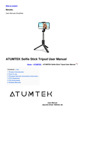
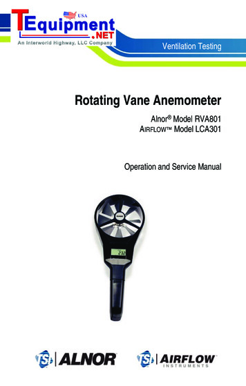
2. HANDLING CAUTIONS2.HANDLING CAUTIONSThis chapter describes important cautions regardinghow to handle the transmitter. Read carefully beforeusing the transmitter.mode was ordered, ‘SQRT’ is inscribed in field *2; ifsquare root output mode was ordered, ‘SQRT’ isinscribed in field *3.The EJA-A Series pressure transmitters are thoroughlytested at the factory before shipment. When thetransmitter is delivered, visually check them to makesure that no damage occurred during ship-ment.Also check that all transmitter mounting hardwareshown in Figure 2.1 is included. If the transmitter wasordered without the mounting bracket or without theprocess connector, the transmitter mounting hardwareis not included. After checking the transmitter, repackit in the way it was delivered until installation.BoltProcess connectorProcess connectorGasket: Refer to USER'S MANUALF0202.EPSFigure 2.2 Name Plate2.2 UnpackingWhen moving the transmitter to the installation site,keep it in its original packaging. Then, unpack thetransmitter there to avoid damage on the way.2.3 StorageU-boltThe following precautions must be observed whenstoring the instrument, especially for a long period.Mounting bracket(L type)U-bolt nutTransmitter mounting bolt(a) Select a storage area which meets the followingconditions: It is not exposed to rain or water. It suffers minimum vibration and shock. It has an ambient temperature and relativehumidity within the following ranges.Ambient temperature:–40 to 85 C without integral indicator–30 to 80 C with integral indicatorRelative humidity:5% to 100% R.H. (at 40 C)Preferred temperature and humidity:approx. 25 C and 65% R.H.Mounting bracket(Flat type)F0201.EPSFigure 2.1 Transmitter Mounting Hardware2.1 Model and SpecificationsCheck(b) When storing the transmitter, repack it as nearly aspossible to the way it was packed when deliveredfrom the factory.(c) If storing a transmitter that has been used, thoroughly clean the chambers inside the cover flanges,so that no measured fluid remains in it. Also makesure before storing that the pressure-detector andtransmitter section are securely mounted.The model name and specifications are indicated on thename plate attached to the case. If the reverse operating mode was ordered (reverse signal), ‘REVERSE’will be inscribed in field *1; if square root display2-1IM 01C21B01-01E
2. HANDLING CAUTIONS2.4 Selecting the InstallationLocationCAUTIONMaximum working pressure of the modelEJA120A differential pressure transmitter is 50kPa {0.5 kgf/cm2}.Should the pressure exceed 50 kPa {0.5 kgf/cm2}, it is possible to break the sensor. Proceedwith caution when applying pressure.The transmitter is designed to withstand severeenvironmental conditions. However, to ensure stableand accurate operation for years, observe the followingprecautions when selecting an installation location.(a) Ambient TemperatureAvoid locations subject to wide temperaturevariations or a significant temperature gradient. Ifthe location is exposed to radiant heat from plantequipments, provide adequate thermal insulationand/or ventilation.(b) Ambient AtmosphereAvoid installing the transmitter in a corrosiveatmosphere. If the transmitter must be installed in acorrosive atmosphere, there must be adequateventilation as well as measures to prevent intrusionor stagnation of rain water in conduits.(c) Shock and VibrationSelect an installation site suffering minimum shockand vibration (although the transmitter is designedto be relatively resistant to shock and vibration).2.6 Waterproofing of CableConduit ConnectionsApply a non-hardening sealant to the threads towaterproof the transmitter cable conduit connections.(See Figure 6.4.2a, 6.4.2b and 6.4.2c.)2.7 Restrictions on Use of RadioTransceiverIMPORTANTAlthough the transmitter has been designed toresist high frequency electrical noise, if a radiotransceiver is used near the transmitter or itsexternal wiring, the transmitter may be affectedby high frequency noise pickup. To test for sucheffects, bring the transceiver in use slowly from adistance of several meters from the transmitter,and observe the measurement loop for noiseeffects. Thereafter, always use the transceiveroutside the area affected by noise.(d) Installation of Explosion-protected TransmittersExplosion-protected transmitters can be installed inhazardous areas according to the types of gases forwhich they are certified. See Subsection 2.9“Installation of Explosion Protected Type Transmitters.”2.5 Pressure ConnectionWARNING Instrument installed in the process is underpressure. Never loosen the process connectorbolts to avoid the dangerous spouting ofprocess fluid. During draining condensate from the pressuredetector section, take appropriate care to avoidcontact with the skin, eyes or body, or inhalation of vapors, if the accumulated process fluidmay be toxic or otherwise harmful.The following precautions must be observed in order tosafely operate the transmitter under pressure.(a) Make sure that the four process connector bolts aretightened firmly.(b) Make sure that there are no leaks in the impulsepiping.(c) Never apply a pressure higher than the specifiedmaximum working pressure.2.8 Insulation Resistance andDielectric Strength TestSince the transmitter has undergone insulation resistance and dielectric strength tests at the factory beforeshipment, normally these tests are not required.However, if required, observe the following precautions in the test procedures.(a) Do not perform such tests more frequently than isabsolutely necessary. Even test voltages that do notcause visible damage to the insulation may degradethe insulation and reduce safety margins.(b) Never apply a voltage exceeding 500 V DC (100 VDC with an internal lightning protector) for theinsulation resistance test, nor a voltage exceeding500 V AC (100 V AC with an internal lightningprotector) for the dielectric strength test.2-2IM 01C21B01-01E
2. HANDLING CAUTIONS(c) Before conducting these tests, disconnect all signallines from the transmitter terminals. Perform thetests in the following procedure:and may cause dangerous condition. Please contactYokogawa for any repair or modification required tothe instrument. Insulation Resistance Test1) Short-circuit the and – SUPPLY terminals in theterminal box.2) Turn OFF the insulation tester. Then connect theinsulation tester plus ( ) lead wire to the shortedSUPPLY terminals and the minus (–) leadwire tothe grounding terminal.3) Turn ON the insulation tester power and measurethe insulation resistance. The voltage should beapplied short as possible to verify that the insulation resistance is at least 20 MΩ.4) After completing the test and being very careful notto touch exposed conductors disconnect theinsulation tester and connect a 100 kΩ resistorbetween the grounding terminal and the shortcircuiting SUPPLY terminals. Leave this resistorconnected at least one second to discharge anystatic potential. Do not touch the terminals while itis discharging. Dielectric Strength Test1) Short-circuit the and – SUPPLY terminals in theterminal box.2) Turn OFF the dielectric strength tester. Thenconnect the tester between the shorted SUPPLYterminals and the grounding terminal. Be sure toconnect the grounding lead of the dielectric strengthtester to the ground terminal.3) Set the current limit on the dielectric strength testerto 10 mA, then turn ON the power and graduallyincrease the test voltage from ‘0’ to the specifiedvoltage.4) When the specified voltage is reached, hold it forone minute.5) After completing this test, slowly decrease thevoltage to avoid any voltage surges.2.9 Installation of ExplosionProtected TypeNOTEFor FOUNDATION Fieldbus and PROFIBUS PAexplosion protected type, please refer to IM01C22T02-01E and IM 01C22T03-00E respectively.CAUTIONThis instrument is tested and certified as intrinsically safe type or explosionproof type. Pleasenote that the construction of the instrument,installation, external wiring, maintenance orrepair is strictly restricted, and non-observanceor negligence of this restriction would result indangerous condition.WARNINGTo preserve the safety of explosionproof equi
Model EJA110A, EJA120A and EJA130A Differential Pressure Transmitters IM 01C21B01-01E IM 01C21B01-01E 11th Edition. i . specified model number break-down and do not cover custom-made instruments. Please note that changes in the specifications, construction, or component parts of the instrument