Transcription
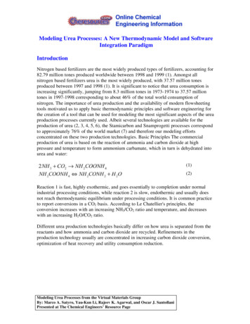
Modeling Urea Processes: A New Thermodynamic Model and SoftwareIntegration ParadigmIntroductionNitrogen based fertilizers are the most widely produced types of fertilizers, accounting for82.79 million tones produced worldwide between 1998 and 1999 (1). Amongst allnitrogen based fertilizers urea is the most widely produced, with 37.57 million tonesproduced between 1997 and 1998 (1). It is significant to notice that urea consumption isincreasing significantly, jumping from 8.3 million tones in 1973-1974 to 37.57 milliontones in 1997-1998 corresponding to about 46% of the total world consumption ofnitrogen. The importance of urea production and the availability of modern flowsheetingtools motivated us to apply basic thermodynamic principles and software engineering forthe creation of a tool that can be used for modeling the most significant aspects of the ureaproduction processes currently used. Albeit several technologies are available for theproduction of urea (2, 3, 4, 5, 6), the Stamicarbon and Snamprogetti processes correspondto approximately 76% of the world market (7) and therefore our modeling effortsconcentrated on these two production technologies. Basic Principles The commercialproduction of urea is based on the reaction of ammonia and carbon dioxide at highpressure and temperature to form ammonium carbamate, which in turn is dehydrated intourea and water:(1)(2)Reaction 1 is fast, highly exothermic, and goes essentially to completion under normalindustrial processing conditions, while reaction 2 is slow, endothermic and usually doesnot reach thermodynamic equilibrium under processing conditions. It is common practiceto report conversions in a CO2 basis. According to Le Chatellier's principles, theconversion increases with an increasing NH3/CO2 ratio and temperature, and decreaseswith an increasing H2 O/CO2 ratio.Different urea production technologies basically differ on how urea is separated from thereactants and how ammonia and carbon dioxide are recycled. Refinements in theproduction technology usually are concentrated in increasing carbon dioxide conversion,optimization of heat recovery and utility consumption reduction.Modeling Urea Processes from the Virtual Materials GroupBy: Marco A. Satyro, Yau-Kun Li, Rajeev K. Agarwal, and Oscar J. SantollaniPresented at The Chemical Engineers’ Resource Page
Stamicarbon Process (Carbon Dioxide Stripping)"NH3 and CO2 are converted to urea via ammonium carbamate at a pressure ofapproximately 140 bar and a temperature of 180-185 C. The molar NH3/CO2 ratioapplied in the reactor is 2.95. This results in a CO2 conversion of about 60% and an NH3conversion of 41%. The reactor effluent, containing unconverted NH3 and CO2 issubjected to a stripping operation at essentially reactor pressure, using CO2 as strippingagent. The stripped-off NH3 and CO2 are then partially condensed and recycled to thereactor. The heat evolving from this condensation is utilized to produce 4.5 bar steam,some of which can be used for heating purposes in the downstream sections of the plant.Surplus 4.5 bar steam is sent to the turbine of the CO2 compressor.The NH3 and CO2 in the stripper effluent are vaporized in a 4 bar decomposition stage andsubsequently condensed to form a carbamate solution, which is recycled to the 140 barsynthesis section. Further concentration of the urea solution leaving the 4 bardecomposition stage takes place in the evaporation section, where a 99.7% urea melt isproduced." (6)Figure 1: Total Recycle CO2 Stripping Urea Process (6)Modeling Urea Processes from the Virtual Materials GroupBy: Marco A. Satyro, Yau-Kun Li, Rajeev K. Agarwal, and Oscar J. SantollaniPresented at The Chemical Engineers’ Resource Page
Snamprogetti Process (Ammonia Stripping)"NH3 and CO2 are converted to urea via ammonium carbamate at a pressure of 150 barand a temperature of 180 C. A molar ratio of 3.5 is used in the reactor giving a CO2conversion of 65%. The reactor effluent enters the stripper where a large part of theunconverted carbamate is decomposed by the stripping action of the excess NH3. Residualcarbamate and CO2 are recovered downstream of the stripper in two successive stagesoperating at 17 and 3.5 bar respectively. NH3 and CO2 vapors from the stripper top aremixed with the recovered carbamate solution from the High Pressure (HP)/Low Pressure(LP) sections, condensed in the HP carbamate condenser and fed to the reactor. The heatof condensation is used to produce LP steam. The urea solution leaving the LPdecomposition stage is concentrated in the evaporation section to a urea melt." (6)Figure 2: Total Recycle NH3 Stripping Urea Process (6)Modeling Urea Processes from the Virtual Materials GroupBy: Marco A. Satyro, Yau-Kun Li, Rajeev K. Agarwal, and Oscar J. SantollaniPresented at The Chemical Engineers’ Resource Page
Thermodynamic ModelingUrea processes are challenging to model from a thermodynamic point of view. From oneside, accurate low pressure equilibrium thermodynamic equilibrium is necessary to modelaqueous urea solutions, while accurate high pressure modeling is necessary to properlymodel the high pressure synthesis reactor. The thermodynamic package also has toproperly take into account the formation of new chemical species, some which are ionic.The effect of minute amounts of inerts in the saturation bubble pressure also has to betaken into account. In addition, the model has to provide reasonable enthalpy and entropyvalues for flowsheeting calculations. Last but not the least, some operations in the ureaprocess require special behavior from the property package calculation engine and propercommunication between the unit operations and the property package system has to beimplemented.The thermodynamic modeling is conveniently divided into high pressure and medium /low pressure areas. In the high-pressure section we have a non-aqueous ionic system whilein the medium / low pressure areas we have an aqueous ionic system.High Pressure EquilibriumInitially the high-pressure section was modeled using a full ionic model as described bySatyro (8). Albeit the model showed good performance when used to model industrialunits, enhancements were possible in terms of computational speed and accuracy withrespect to ammonia and carbon dioxide vapor compositions at the outlet of the ureasynthesis reactor. The majority of the time spent in thermodynamic calculations wasdetermined to be in the convergence of the ionic chemical equilibrium, and anysimplification in that area would have significant impact in the calculation speed, andtherefore would allow the use of the model not only for steady state calculations but alsodynamic calculations necessary for safety studies and operator training.The reactive system was simplified by considering all the chemical species in theirmolecular states. This is not true from a purely physical-chemical point of view, since thereactions happening in the liquid phase at high pressure are well represented by thefollowing reaction system (8):(3)(4)(5)(6)(7)The equilibrium constants for the equations above are functions of temperature, and thereaction equilibrium is supposed to be independent of pressure. Therefore, the equilibriumModeling Urea Processes from the Virtual Materials GroupBy: Marco A. Satyro, Yau-Kun Li, Rajeev K. Agarwal, and Oscar J. SantollaniPresented at The Chemical Engineers’ Resource Page
compositions for the several species (molecular and ionic) can be represented as inEquation 8:(8)Where the index i represents one of the chemical reactions defined by Equations 1 to 4, xis the composition vector in the liquid phase, T is the liquid phase temperature and the K'son the right of Equation 5 are defined as in Equations 9a and 9b.(9a)(9b)Whereis the activity coefficient andthe components present in reaction i.is the stoichiometric coefficient for each ofThe calculation of ionic species activity coefficients is somewhat laborious and the detailscan be found in Satyro (8). Since the chemical equilibrium has to be evaluated at everyiteration when calculating liquid phase fugacity coefficients, any reduction incomputational load while keeping accuracy will translate into substantial time saving.Therefore, the reaction system defined by Equations 3 to 7 was replaced by the followingsimplified system:(10)(11)(12)At equilibrium, the actual composition of the liquid phase will be denoted by z and theequilibrium expression is then given by:(13)Modeling Urea Processes from the Virtual Materials GroupBy: Marco A. Satyro, Yau-Kun Li, Rajeev K. Agarwal, and Oscar J. SantollaniPresented at The Chemical Engineers’ Resource Page
For convenience we note that the fugacity coefficient in the liquid phase is given by thefollowing:(14)Note that even if the solution was ideal from a physical point of view the fugacitycoefficient is not unitary unless chemical reactions are not present. This is caused by thefact that the ratio zi / xi will be unitary only and only if the liquid phase does not presentchemical reactions. The salts present in solution, ammonium carbamate, urea andammonium bicarbonate are not present in the vapor phase and therefore have infinitesimalvolatility.Careful analysis of the performance of different activity coefficient models on therepresentation of ammonia and water vapor-liquid equilibrium determined the final modelused in this study and a 4 suffix Margules expression was determined optimal for ourpurposes as defined in the equations below:(15)(16)(17)(18)Where dij is a symmetric, temperature independent interaction parameter and aij is definedas:(19)Standard state fugacities are determined based on vapor pressures for most componentswhile specially determined standard state fugacities for ammonia and carbon dioxide areused, which are valid from 200 to 500 K.Modeling Urea Processes from the Virtual Materials GroupBy: Marco A. Satyro, Yau-Kun Li, Rajeev K. Agarwal, and Oscar J. SantollaniPresented at The Chemical Engineers’ Resource Page
High Pressure Data RegressionBinary interaction parameters were determined for the following binary pairs based onpublished experimental data as described in Table 1.Table 1: Binaries and Ranges for Urea ModelingTypical results for ammonia/water, urea/water, and urea/ammonia are presented in Figures3, 4, and 5.Modeling Urea Processes from the Virtual Materials GroupBy: Marco A. Satyro, Yau-Kun Li, Rajeev K. Agarwal, and Oscar J. SantollaniPresented at The Chemical Engineers’ Resource Page
Figure 3: Ammonia Water Vapor-Liquid Equilibrium at 80 CFigure 4: Urea/Water Bubble PressuresModeling Urea Processes from the Virtual Materials GroupBy: Marco A. Satyro, Yau-Kun Li, Rajeev K. Agarwal, and Oscar J. SantollaniPresented at The Chemical Engineers’ Resource Page
Figure 5: Urea/Ammonia Bubble PressuresThe interaction parameters for the binaries defining the partial pressures of carbon dioxideand ammonia at high pressures were determined based on data published by Lemkowitzand co-workers (14, 15, and 16). The results show an actually better performance than theprevious ionic model as shown in the isotherms at 150, 180 and 200 C. The experimentalpoints for each isotherm were determined by constructing Clapeyron plots for eachisoconcentrations published by Lemkowitz and then determining the bubble pressure foreach isotherm.Modeling Urea Processes from the Virtual Materials GroupBy: Marco A. Satyro, Yau-Kun Li, Rajeev K. Agarwal, and Oscar J. SantollaniPresented at The Chemical Engineers’ Resource Page
Figure 6: Reactive Isotherm at 150 C. Red line is molecular model, open squaresUREA 2.0 using ionic modelFigure 7: Reactive Isotherm at 180 C. Red line is molecular model, open squaresUREA 2.0 using ionic modelModeling Urea Processes from the Virtual Materials GroupBy: Marco A. Satyro, Yau-Kun Li, Rajeev K. Agarwal, and Oscar J. SantollaniPresented at The Chemical Engineers’ Resource Page
Figure 8: Reactive Isotherm at 200 C. Red line is molecular model, open squaresUREA 2.0 using ionic modelLow and Medium Pressure EquilibriumAt low and medium pressures the mixtures are mostly concentrated solutions of water andurea with dissolved carbon dioxide and ammonia. A considerable body of work exists forsour water systems without dissolved urea (17, 18, 19, and 20). In this work, the modelproposed by Edwards and co-workers (18) is used with specially determined interactionparameters between ammonia / urea and carbon dioxide / urea to properly account thepresence of urea in the solution (21).Equilibrium Reactor ModelingA useful tool for mass and energy balances in a urea plant is an equilibrium reactor, whichcan be used to estimate the performance of actual reactors at optimum conditions (from athermodynamic point of view). Which can be used as a first approximation for thesynthesis reactor. Usually reactors with more than nine baffles approach the results onewould get by assuming complete chemical equilibrium as reported by Uchino (5). Also,equilibrium reactors provide a convenient tool for initial studies on how water will affectthe reactor performance and can replace empirical graphical relationships used in handcalculations (22, 23). For the we use the ionic reaction system defined by reactions 3-7.Comparisons between predicted and calculated results can be found in Figure 9.Modeling Urea Processes from the Virtual Materials GroupBy: Marco A. Satyro, Yau-Kun Li, Rajeev K. Agarwal, and Oscar J. SantollaniPresented at The Chemical Engineers’ Resource Page
Figure 9: Error in Predicting CO2 Conversion for Urea Equilibrium Reactor (24)Modeling of specific urea processing unit operationsSeveral of the unit operations found in the urea process are not found in processsimulators, and some ingenuity is required for their proper modeling. This sectiondescribes some of these unit operations and the steps taken for their modeling. Thediscussion is based on the Stamicarbon process.Urea Synthesis Kinetic Reactor ModelBefore the urea synthesis reactor model can be used for predictions, it needs to be tuned.There are two major parameters that are determined during the tuning process. These area) determining the amount of ammonium carbamate in the reactor feed and b) theequivalent kinetic reactor volume. In order to do this, reactor performance and feedcomposition needs to be known for at least one operating point.Determine the amount of Carbamate in the FeedThe feed composition is known in terms of CO2 and NH3 and not in terms of the amountof carbamate present. The first step is to use the UREA equilibrium reactor in order tocompute the equilibrium carbamate leaving the reactor at the process reactor outlettemperature. In the equilibrium reactor, the urea reaction equilibrium constant efficiency isadjusted such that the actual CO2 conversion is matched. Then the inlet carbamate contentis adjusted (keeping the total amount of CO2 and ammonia constant) to obtain an adiabaticreactor.Modeling Urea Processes from the Virtual Materials GroupBy: Marco A. Satyro, Yau-Kun Li, Rajeev K. Agarwal, and Oscar J. SantollaniPresented at The Chemical Engineers’ Resource Page
Reactor Kinetic ModelThe plate type synthesis reactor can be modeled as a set of equilibrium and reactor stages.Since the Carbamate formation reaction is fast it can be modeled as an equilibriumreaction. The carbamate decomposition into urea is slow and is modeled as a kinetic(CSTR) reaction. The equilibrium constants for the carbamate formation are well known,as are the kinetic parameters for the carbamate decomposition into urea. It is found that forplate type reactors, 3 stages are often enough to model the synthesis reactor. A typicalexample is shown in Figure 10.Figure 10: Kinetic Reactor ModelDetermine kinetic reactor volumeThe kinetic reactor volume of each stage can be adjusted such that the desired ureaformation is achieved at the known process conditions. Thereafter the reactor model canbe used for predicting the performance due to changing flows and compositions.High Pressure Stripper ModelThe high-pressure stripper is a carbamate decomposer. The high concentration of CO2pushes the carbamate decomposition toward completion. This unit-operation is a nonequilibrium process and cannot be modeled using standard equilibrium thermodynamics.The presence of the CO2 strips the reactor products of its ammonia and CO2. In addition,any CO2 and ammonia produced by carbamate decomposition is also stripped by theflowing CO2. This process seems to be mass transfer controlled, and it is currentlymodeled by assuming that all the free CO2, ammonia and all the products of thedecomposed carbamate get carried up with the stripping CO2. Heat balances reveal thatabout 75% of the energy in the High Pressure Stripper is consumed by the carbamatedecomposition and the rest is taken up as sensible heat. A component-splitter unitoperation such as the one provided by the HYSYS process simulator (25) is used to modelthis non-equilibrium process. Knowing the distribution of the energy for carbamateModeling Urea Processes from the Virtual Materials GroupBy: Marco A. Satyro, Yau-Kun Li, Rajeev K. Agarwal, and Oscar J. SantollaniPresented at The Chemical Engineers’ Resource Page
decomposition and sensible heat it is possible to create a semi-predictive model of theStripper as steam and process flow changes.High Pressure ScrubberThe vent from the synthesis reactor is scrubbed in this vessel. Some carbamate is formedand heat has to be removed from the system. There are two components to the removedheat: the sensible heat and the heat of reaction due to carbamate formation. The amount ofcarbamate formed can be back calculated from the process temperatures and the amount ofheat supplied.High Pressure CondenserThis unit operation supplies the feed to the synthesis reactor. As such the amount ofcarbamate formed and leaving this condenser is known (see Reactor Tuning). Hence thisunit-operation can be modeled as a simple conversion reactor where the CO2 conversion toammonium carbamate is known.Low Pressure Desorbers and Hydrolyzer ModelThis part of the flowsheet can be directly modeled using Urea . No specialconsiderations are required. Predicted are within 0.5 F of plant performance andpredicted compositions are within 1% of plant measurements.Software ImplementationProcess simulation is a tool that shows its power when widely available to processengineers, allowing them to perform better understand the process, propose changes to theprocess to fine tune performance based on particular characteristics of their plants,markets and economic situation. Therefore, although a rigorous thermodynamic model ofthe process is a necessary condition for success, it is not sufficient. Some proprietary ureasimulation programs exist (7, 26), but they seem to be available only to a handful of users.Our objective was to combine excellence in science with excellence in software to create asolution, which in turn can be used by a wide audience, made up mostly of processengineers, not thermodynamic specialists. Therefore, a robust implementation of themathematical model would have to be combined with a robust software implementation toallow physical property calculations to be available over a wide range of softwareplatforms (27).Our choice was to create a central core of classes programmed using the C programming language (26). This central core implements all the necessary supportfunctions for the creation of physical property systems, and it is very flexible in terms ofphysical properties it can handle. Complete support for pure component propertyconfiguration, interaction parameter configuration, physical property definition andproperty package definition (which is nothing more than a collection of physicalproperties, pure components and interaction parameter matrices) is provided. This allowsModeling Urea Processes from the Virtual Materials GroupBy: Marco A. Satyro, Yau-Kun Li, Rajeev K. Agarwal, and Oscar J. SantollaniPresented at The Chemical Engineers’ Resource Page
us to create complete property packages with maximum reuse of parts in an extremelyefficient and fast manner.On top of this core set of classes, software interfaces are implemented allowing ourproperty package system to be used by many diverse applications, ranging from a steadystate and dynamic simulator such as HYSYS to batch process simulators, operator trainingsimulators and productivity tools such as Excel, Java and Visual Basic. This functionalityis shown schematically in Figure 11.Figure 11: Property Package System InterfacesThis modern approach to software engineering provides immediate benefit to the user.Usually a process engineer will be familiar with a process simulator. By installing ourproperty package system in his or her computer, the user has immediate access to thephysical property calculations provided by our physical property system without having tolearn how to use a new process simulator. For example, the HYSYS process simulator wasbuilt with an open software architecture in mind, and our property package provides aninterface, which HYSYS can recognize. From that point on, the user can select ourproperty package system directly from inside the simulator:Modeling Urea Processes from the Virtual Materials GroupBy: Marco A. Satyro, Yau-Kun Li, Rajeev K. Agarwal, and Oscar J. SantollaniPresented at The Chemical Engineers’ Resource Page
Figure 12: Selecting Virtual Materials Group Property Package System from insidethe HYSYS Process SimulatorFigure 12 shows what the user of the HYSYS process simulator would see in the basisenvironment. The basis is the section of the program where thermodynamic models andcomponents are selected for the simulation. Note the Virtual Materials Group PropertyPackage System appears in the Base Property Package Selection scrollable list. WithVMG Property Package selected, the form displayed on the right appears, where the usercan select the appropriate Virtual Material to represent his or her system of interest asshown in Figure 13.Modeling Urea Processes from the Virtual Materials GroupBy: Marco A. Satyro, Yau-Kun Li, Rajeev K. Agarwal, and Oscar J. SantollaniPresented at The Chemical Engineers’ Resource Page
Figure 13: Selecting a Virtual Material to represent a specific processHardware Like SoftwareWe believe that software to be useful for engineers should behave like a piece ofhardware. This has two significant conceptual implications:1. Software should be able to be plugged into other applications without any interventionfrom the software vendor. This was explored in the previous item.2. Users should know how good and how bad the software is when used to simulate hisprocess. Virtual Materials Group performs extensive validations on its propertypackages and is able to create a "boiler plate" for each property package it produces,thus allowing engineers to know a-priori the performance of a property package. Thisin turn allows the user to critically evaluate the performance of the property packageand interact with Virtual Materials in the event errors are not reported for a specificcondition of interest.Validation of property package systems is a fundamental part of an industrial gradeproperty package system and considerable effort is spent in this feature before a propertypackage is actually released. For example, UREA 2.0's boilerplate is reproduced inTable 3.Modeling Urea Processes from the Virtual Materials GroupBy: Marco A. Satyro, Yau-Kun Li, Rajeev K. Agarwal, and Oscar J. SantollaniPresented at The Chemical Engineers’ Resource Page
Table 3: UREA Version 2.0 Boiler Plate – Temperatures (K) and Pressures (kPa)Putting It All TogetherSeveral different urea production flowsheets were successfully modeled using the physicalbehavior modeled by Virtual Materials Property Package System and the calculationsequencing provided by AEA' s Software Engineering process simulator HYSYS.Engineers can be productive from the start by having access to rigorous thermodynamiccalculations while not having to learn a new process simulation tool. Table 4 summarizesthe typical errors found when modeling a urea plant using UREA .Modeling Urea Processes from the Virtual Materials GroupBy: Marco A. Satyro, Yau-Kun Li, Rajeev K. Agarwal, and Oscar J. SantollaniPresented at The Chemical Engineers’ Resource Page
Table 4: Model versus actual plant comparisonsConclusions and Future WorkA rigorous, general-purpose model for urea production processes was successfullyimplemented and experimentally verified against actual plant data. The model wasimplemented using modern software technology, which allows the model to be used inprocess simulators or other applications such as spreadsheets or operator training software.Currently work is being done in further refining the low and medium pressurethermodynamic models and in the creation of a mass transfer based high-pressure steadystate decomposer model.Modeling Urea Processes from the Virtual Materials GroupBy: Marco A. Satyro, Yau-Kun Li, Rajeev K. Agarwal, and Oscar J. SantollaniPresented at The Chemical Engineers’ Resource Page
.17.18.19.20.21.22.23.24.25.26.27.International Fertilizer Industry Association, http://www.fertilizer.org/index.htmL. W. Codd, "Chemical Technology : An Encyclopedic Treatment : The Economic Application ofModern Technological Developments ", Barnes and Noble, 1975J.A. Kent, "Riegel's Handbook of Industrial Chemistry", Van Nostrand Reinhold Company Inc, 1983I. Froment, F. Gilbert, "4 th International Symposium on Large Chemical Plants", Antwerp, 1979,Elsevier; Scientific Publishing Company, 1979R.A. Meyers, "Handbook of Chemical Production Processes", McGraw-Hill, 1986"Production of Urea and Urea Ammonium Nitrate", European Fertilizer Manufacturers' Association,1995.Dente, M.; Pierucci, S.; Sogaro, A.; Carloni, G. and Rigolli, E.; "Simulation Program for Urea Plants",Comput. Chem. Engng., Vol. 21., No. 5, 389-400, 1988Satyro, M.A.; "UREA - Modeling for Urea Production Processes", Virtual Materials Group, Calgary,Alberta, Canada, 2000Gillespie, P.C.; Wilding, W.V.; Wilson, G.M.; "Vapor -Liquid Equilibrium Measurements on theAmmonia -WaterTillner-Roth, Reiner; Friend, D.G.; "A Helmholtz Free Energy Formulation of the ThermodynamicProperties of the Mixture {Water Ammonia}"; J. Phys. Chem. Ref. Data, Vol. 27., No. 1, 1998Harvey, A.H.; "Semiempirical Correlation for Henry's Constants over Large Temperature Ranges";AIChE Journal, 42, No. 5, May 1996API Technical Data Book, American Petroleum Institute, 1992Chao, G.T.; "Urea, its Properties and Manufacture"; Chao's Institute, Taipei, Taiwan, 1967Lemkowitz, S.M.; Goedegebuur, J. and van den Berg, P.J.; "Bubble Point Measurements in theAmmonia -Carbon Dioxide System", J. Appl. Chem. Biotechnol., Vol. 21, 1971Lemkowitz, S.M.; Zuidam, J. and van den Berg, P.J.; "Phase Behavior in the Ammonia-Carbon DioxideSystem at and above Urea Synthesis Conditions"; J. Appl. Chem. Biotechnol., Vol. 22, 1972Lemkowitz, S.M.; de Cooker, M.G.R.T. and van den Berg, P.J.; "An Empirical Thermodynamic Modelfor the Ammonia -Water-Carbon Dioxide System at Urea Synthesis Conditions"; J. Appl. Chem.Biotechnol., Vol. 23, 1973Edwards, T.J., Newman, J. and Prausnitz, J.M.; "Thermodynamics of Aqueous Solutions ContainingVolatile Weak Electrolytes"; AIChE J., 21, 1975Edwards, T.J.; Maurer, G.; Newman, J. and Prausnitz, J.M.; "Vapor-Liquid Equilibria inMulticomponent Aqueous Solutions of Volatile Weak Electrolytes"; AIChE J., 24, 1978Pawlikowski, E.M.; Newman, J. and Prausnitz, J.M.; "Phase Equilibria for Aqueous Solutions ofAmmonia and Carbon Dioxide", Ind. Eng. Chem. Process Des. Dev., 21, 1982Kawazuizhi, K. and Prausnitz, J.M., "Correlation of Vapor-Liquid Equilibrium for the SystemAmmonia -Carbon Dioxide-Water; Ind. Eng. Chem. Res., 26, 1987Wicar, S.; "Calculation of vapour-liquid equilibrium in the system urea, ammonia, carbon dioxide andwater"; British Chemical Engineering, 1963Mavrovic, I.; "Find Equilibrium Urea Yield"; Hydrocarbon Processin g, April 1971Kucheryavyi, V.I.; Gorlovskii, D.M. and Konkina, T.N.; "Equilibrium Degree of the Conversion ofCarbon Dioxide in the Synthesis of Urea"; Khim. Prom., 45, 1969Inoue, S.; Kanai, K.; Otsuka, E.; "Equilibrium of Urea Synthesis. I.", Bulletin of the Chemical Societyof Japan, Vol. 45, 1972HYSYS User's Manual, AEA Engineering Software, 2000Stroustrup, B.; "The Design and Evolution of C "; AT&T Bell Labs, 1994Virtual Materials User's Manual; Virtual Materials Group, Calgary, Alberta, Canada, 2000,http://www.virtualmaterials.comModeling Urea Processes from the Virtual Materials GroupBy: Marco A. Satyro, Yau-Kun Li, Rajeev K. Agarwal, and Oscar J. SantollaniPresented at The Chemical Engineers’ Resource Page
High Pressure Data Regression Binary interaction parameters were determined for the following binary pairs based on published experimental data as described in Table 1. Table 1: Binaries and Ranges for Urea Modeling Typical results for ammonia/water, urea/water, and urea/ammonia are presented in Figures 3, 4, and 5.