Transcription
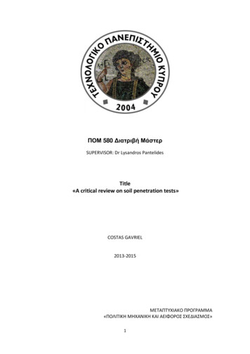
International Journal of Applied Dental Sciences 2019; 5(2): 233-240ISSN Print: 2394-7489ISSN Online: 2394-7497IJADS 2019; 5(2): 233-240 2019 IJADSwww.oraljournal.comReceived: 24-02-2019Accepted: 26-03-2019Sunita MarothiyaLecturer, Department ofOrthodontics and DentofacialOrthopedics, Sri AurobindoCollege of Dentistry and PGInstitute, Indore, MadhyaPradesh, IndiaVedant PatelLecturer, Department ofProsthodontics and Crown &Bridge and Implantology, IndexInstitute of dental Sciences,Indore, Madhya Pradesh, IndiaDivya JainPG Student, Department ofProsthodontics and Crown &Bridge and Implantology,Darshan Dental College andHospital, Udaipur, Rajasthan,IndiaShubhangi AgrawalPG Student, Department ofProsthodontics and Crown &Bridge and Implantology,Darshan Dental College andHospital, Udaipur, Rajasthan,IndiaSurbhi JoshiTutor, Sri Aurobindo College ofDentistry and PG Institute,Indore, Madhya Pradesh, IndiaVipin PandeyTutor, Sri Aurobindo College ofDentistry and PG Institute,Indore, Madhya Pradesh, IndiaCorrespondenceSunita MarothiyaLecturer, Department ofOrthodontics and DentofacialOrthopedics, Sri AurobindoCollege of Dentistry and PGInstitute, Indore, MadhyaPradesh, IndiaCone beam computed tomography in orthodontics: Aliterature reviewSunita Marothiya, Vedant Patel, Divya Jain, Shubhangi Agrawal, SurbhiJoshi and Vipin PandeyAbstract3D imaging is quickly emerging as the standard of care in orthodontics as new ultralow-dose CBCTtechnology offers safer and more affordable volumetric scanning than ever before. Orthodontist routinelyuse 2-dimensional (2D) static imaging technique, but deepness of structures cannot be obtained andlocalized with 2-D imaging. Introduction of cone-beam computed tomography (CBCT) for themaxillofacial region provides opportunities for dental practitioners to request multiplanar imaging. Thisreview covers the principles, image acquisition and image reconstruction, various display modes ofCBCT and its various application in orthodontics.Keywords: 3D imaging, cone-beam computed tomography (CBCT), computed tomography (CT)1. IntroductionDr. B. Holly Broadbent Sr. ushered in the age of 3D orthodontics when he first proposedtaking a lateral and frontal head film simultaneously to evaluate patients in multiple planes ofspace [1]. Today we have the technology to image and visualize the entire head in 3D. Conebeam computed tomography (CBCT) has made a remarkable entry into the field ofOrthodontic diagnosis the last few years. It produces impressive 3D color pictures, incomparison to the black & white 2D projections we have been accustomed to. 2 It offers thedistinct advantage of 1:1 geometry, which allows accurate measurements of objects anddimensions, therefore it is frequently applied for maxillofacial imaging for better diagnosticaccuracy and treatment planning.3The aims of this literature review to illustrate the applicationof CBCT in orthodontics through its different and unique image display of maxillofacialregion.2. Computed Tomography (CT)CT imaging, also called computerized axial tomography (CAT) imaging. It was invented byGodfrey Hounsfield in England at the end of the 1960’s and by Allan Cormack in the USAwho developed image reconstruction mathemetics to provide cross sectional of head. Bothshared the Nobel Prize in medicine in 1979 [4].The term tomography comes from the Greek words tomos, which means to slice or to divide,and graphein, which means to write. So, by definition it is an imaging of an object byanalyzing its slices [5].In CT scanners, x-ray source and solid-state detector are mounted on a rotating gantry. Dataare acquired using a narrow “fan-shaped” x-ray beam transmitted through the patient. Thepatient is imaged slice-by-slice, usually in the axial plane, and interpretation of the images isachieved by stacking the slices to obtain multiple 2D representations [6]. In early CT scannersboth x-ray source and detectors revolved around the patient the and only single row ofdetectors were present for capturing data. Recent advances in CT include multirow detectors,having 4 to 64 rows of detectors which can acquired up to 320 slices simultaneously [7] (Fig.1). 233
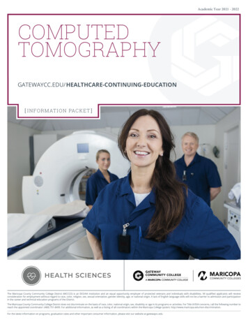
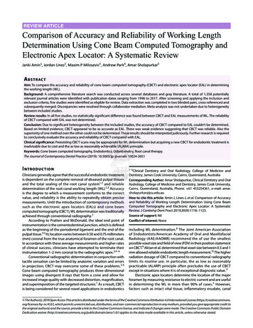
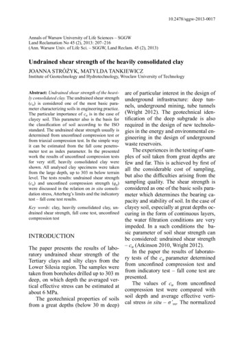
International Journal of Applied Dental SciencesFig 1: Mechanical geometry of CT scanners. A, Both the x-ray tube and the detector array revolve around the patient. B, Only the x-ray tuberotates; radiation detection is accoumpalished by the use of a fixed circular array of as many as 1000 detectors .3. Cone Beam Computed Tomography (CBCT)In 1982, Richard Rob a biophysicist and computer scientist atMayo clinic developed the first CBCT (built forangiography). It uses a “Cone shaped” divergent beam ofionizing radiation like X-rays and a 2D area detector mountedon a rotated gantry to acquire multiplanar sequentialprojection images in one single scan around the area ofinterest and the scanning software collects this projection dataand reconstructs it, and producing volumetric data [8].Imaging may be performed with the patient seated, supine, orstanding. The patient’s head is positioned and stabilizedbetween the x-ray generator and detector by a head holdingapparatus [7].3.1 Advantage of Cone shaped x-ray beam over fan shape:Fan beam CT scanners produce images in slices. The slicesneed to be put together in the correct order and orientation toconstruct the volume from which subsequent reoriented slicescan be made and precision in measurement can becompromised and anisotrophic type of image are formed. InCone beam CT scanners [8] (Figure 2)Fig 2: X-ray beam projection scheme comparing a single detector array fan-beam CT (a) and cone-beam CT (b) geometry3.2 CBCT Image ReconstructionIt consist of two stages: acquisition and reconstruction. CBCTinvolves the rotational scan exceeding 180 degree of an x neously. During rotation many exposure are made atfixed interval. A single projection image is called basis imageand a complete series of basis image is called raw orprojection images which cannot be view directly (Acquisitionstage). This images undergoes sophisticated mathematicalalgorithm in the reconstruction stage which recombined allthe images to form a volumetric data which is equal in alldimension [8].3.3 CBCT Advantages [8].3.3.1 Variable Field of View (FOV)An optimal FOV can be selected for each patient based ondisease presentation and the region designated to be imaged.While an orthodontist is likely to wish to see the fullmaxillofacial complex images, regional high resolution scansmight be appropriate for such tasks as evaluating the positionof impacted teeth.3.3.2 Sub millimeter ResolutionCBCT units use megapixel solid state devices for x-raydetection providing a minimal voxel resolution of between0.07 mm and 0.25 mm isotropically, exceeding most highgrade multislice CT capabilities in terms of spatial resolution.This nominal resolution approaches that required for the mostdiscerning tasks in orthodontics-the determination ofperiodontal ligament space, particularly in cases of suspectedankylosis.3.3.3 High speed scanningCBCT generally acquires all basis projection images in asingle rotation, so scan time can be minimized. Whencompared with medical fan beam CT systems, particularly forhigh resolution, each slice thickness sequence can take up toseveral tens of seconds. Although faster scanning time usuallymeans fewer basis images from which to reconstruct thevolumetric data set, motion artifacts due to subject movementare reduced. 234
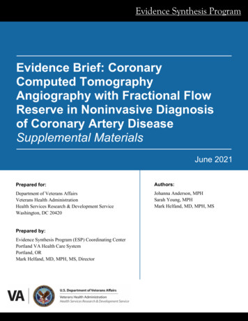
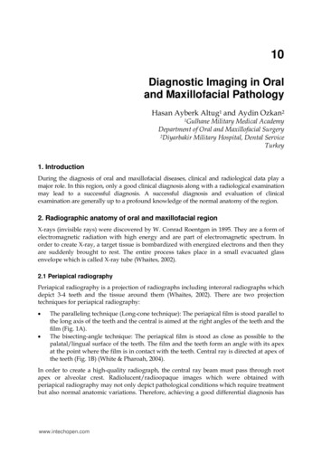
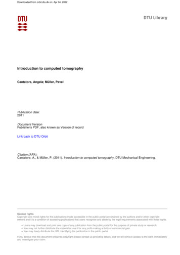
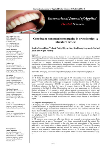
International Journal of Applied Dental Sciences3.3.4 Dose ReductionReports indicate that CBCT patient absorbed dose is reportedto be significantly reduced when compared with conventionalCT [9-11].3.3.5 Voxel isotrophyCBCT uses a 2D detector and the same high resolution isobtained in the longitudinal slice (body axis direction) andlateral slice (transverse direction). This voxel representation isknown as isotropic. Because of this characteristic, coronalMPR of CBCT data has the same resolution as axial data. Inconventional CT, the voxels are anisotropic - rectangularcubes where the longest dimension of the voxel is the axialslice thickness and is determined by slice pitch, a function ofgantry motion.3.3.6 Real-Time Analysis and EnhancementReconstruction of CBCT data is performed natively using apersonal computer. As the original data are isotropic, it can bereoriented such that the patient’s anatomic features arerealigned. This is particularly important for cephalometricanalysis. Finally, the availability of cursor-drivenmeasurement algorithms provides the clinician with aninteractive capability for real-time dimensional assessment.3.3.7 Display Modes Unique to Maxillofacial ImagingCBCT units initially reconstruct the projection data to providestandard viewing layouts in three orthogonal planes-frontal(sagittal), lateral, and superior (axial) (Figure 3).Fig 3: Initial presentation of CBCT image slices in three orthogonal planes3.3.8 Multiplanar ReformattingReformatting images at a nonorthogonal or obliqueorientation, referred to as multiplanar reformatting (MPR), thesame spatial resolution as the original voxel size. Structuresare not particularly well visualized and represented asdisplayed in the sagittal and/or coronal planes ------MPR canbe useful in these instances. The orientation of this formattingis viewer derived and can be: Linear oblique (useful for temporomandibular jointassessment) (Fig. 4)Fig 4: Bilateral linear oblique multiplanar reformation through lateral and medial poles of the mandibular condyle on the axial image (a)providing corrected coronal, limited field-of-view, thin-slice temporomandibular views (b) demonstrating right condylar hyperplasia 235
International Journal of Applied Dental Sciences Curved oblique (providing a “panoramic” image) (Fig. 5) orSerial transplanar (providing sequential contiguous cross-sectional imaging orthogonal MPR) (Fig. 5)Fig 5: Reformatted panoramic image (a) providing reference for multiple narrow trans-axial thin cross-sectional slices (b) of radiolucent bonypathology in the left mandible, demonstrating bucco-lingual expansion and location of the inferior alveolar canal.3.3.9 Voxel VisionVolumetric vision refers to the approaches that can be appliedto visualize 2D data in a 3D mode. Because of the largenumber of component slices in any MPR image and thedifficulty in relating adjacent structures, three techniques havebeen developed to visualize adjacent voxels: Variable slice thickness viewing Maximum intensity projection (MIP) Indirect volume rendering (IVR) Variable slice thickness viewingMost simply, any multi-planar image or orthogonal image canbe "thickened" by increasing the number of adjacent voxelsincluded in the display. This creates an image that representsa specific volume of the patient. The addition of intensityvalues of adjacent voxels throughout a particular section sliceby increasing the section thickness creates a "slab" of thesection referred to as a "ray sum”. This mode can be used togenerate simulated projections such as lateral cephalometricimages. These can be created from full thickness (130-150mm) perpendicular MPR images (Fig. 6).Fig 6: An axial projection (a.) is used as the reference image. A section slice is identified (orange) which, in this case, corresponds to the midsagittal plane and the thickness of this increased to include both left and right sides of the volumetric dataset. As the thickness of the "slab"increases, adjacent voxels representing elements such as air, bone and soft tissues are added. The resultant image generated (b.) provides asimulated lateral cephalometric. Maximum intensity projection (MIP) [12]MIP is a 3D visualization technique that is achieved byevaluating each voxel value along an imaginary projection rayfrom the observer's eyes within a particular volume ofinterest. It is a simpler process. MIP images are achieved bydisplaying only the highest voxel value within a particularthickness. This mode produces a “pseudo” 3D structure and isparticularly useful in representing the surface morphology ofthe maxillofacial region. MIP is particularly useful inrepresenting the bony surface morphology of themaxillofacial region. In maxillofacial imaging, it is oftenbetter than surface rendered 3D images to evaluate thelocation of third molars or can be applied to evaluate thepresence of a foreign body material or calcification in softtissue structures (Fig 7). 236
International Journal of Applied Dental SciencesFig 7: In this example, an axial projection (a.) is used as the reference image. A projection ray is identified (orange) throughout the entirevolumetric dataset along which individual voxels are identified, each with varying grayscale intensity corresponding to various tissue densitiessuch as fat, muscle, air and bone. Indirect volume rendering/ Shaded SurfaceRendering (SSR) [15, 16]It is a complex process requiring selection of intensity ordensity of the grayscale level of the voxels to be displayedwithin a an entire data set (called “segmentation“).This istechnically demanding as it is necessary for the operator toprovide either pre-set or manual inputs as to which voxelsshould be included. It is also computationally difficult,requiring specific software. However, the process provides avolumetric surface reconstruction with depth (Fig. 8).Fig 8 A). Visualization of the full data volume by mean of a shaded surface display with the threshold set to show hard tissues (bone and teeth)only. B) The data attenuation values corresponding to the soft tissues were made partially transparent, allowing for visualization of theunderlying skeleton and teeth.4. Application of CBCT in Orthodontics4.1 Impacted and transposed teeth [14, 15]Most common indications for CBCT imaging in orthodontics (Fig. 9)Fig 9: Depiction of impacted maxillary canines using a conventional 2D panorex (A) and 3D volumetric rendering. The 3D images permit clearvisualization of the location and relationships of the impacted canines to adjacent structures, as well as the presence of any root resorption. Itfacilitates treatment decisions, including determination of teeth to be extracted. If yes then the optimal surgical approach, appropriate placementof attachments, and biomechanics planning. 237
International Journal of Applied Dental Sciences4.2 Cleft lip and palate (CL/P) [14]3D volumetric reconstructions of a patient with bilateral CL/Pare useful in obtaining detailed information on the magnitudeof the defect and the status and position of teeth at the defectsite (Fig. 10).Fig 10: Surface rendered volumetric reconstruction of patient having cleft lip defect4.3 Orthognathic and craniofacial anomalies surgicalplanning and implementation [14] CBCT combined withcomputer-aided surgical simulation (CASS) or computeraided Orthognathic surgery (CAOS) offers refining diagnosisand optimizing treatment objectives in 3D virtual treatmentplanning to improve surgical procedures and outcomes (Fig.11).Fig 11: Virtual surgical treatment planning for a patient to visualize and determine the magnitude of maxillary and mandibular4.4 Asymmetry [14, 16]When large differences exist between bilateral structures,CBCT scans enable the use of a technique called “mirroring”in which the normal side is mirrored onto the discrepant sideso as to simulate and visualize the desired end result, as wellas to plan the surgery to facilitate correction (Fig. 12).(Metzger et al. 2007) 238
International Journal of Applied Dental Sciences4.7 TMJ degeneration, progressive bite changes functionalshifts, and responses to therapyThe comparison of the CBCT imaging with complexpanoramic radiography and linear tomographic views wasmade by Honey et al. where he presented the accuracy andsuperior reliability of the CBCT images for the diagnosis ofcondylar morphology and erosion [18] (Figure 15)Fig 12: Mirroring on a mid-sagittal plane for quantitation ofmandibular asymmetry4.5 CBCT in OSA (Obstructive Sleep Apnea) [17]Measuring the size and shape of the pharynx is critical todiagnose obstructive sleep apnea and when contemplatingsurgery, particularly maxillary or mandibular setbackprocedures. In cross-section the pharynx is more ellipticalthan round and thus 2D information from a lateralcephalogram may be insufficient or misleading for diagnosisof obstructive sleep apnea (Fig. 13).Fig 15: Visualization of the TMJ in the axial (A), coronal (B), andsagittal (C) planes, as well as 3D volumetric reconstructions herevisualized from the buccal (D), medial (E), medio-inferior (F), andanteroinferior (G). In 3D can help in the identification of pathologicchanges, including sclerosis, flattening, erosions, osteophytes,abnormalities in joint spaces, and responses of the joint tissues totherapy.4.8 Interpreting the Cone Beam Data Volume for OccultPathology [19]Sinus blockage, a calcified plaque, osteoarthritic changes inthe vertebral bodies or temporomandibular joint (TMJ)condyle, or even a cysts, tumor, were not anticipated orsuggested by clinical examination or the medical history.These findings are termed “occult” (Fig. 16).Fig 13: Cone-beam computed tomography image of the pharyngealairway4.6 Alveolar boundary conditions [14]Compromised pretreatment alveolar boundary conditions maylimit or interfere with the planned or potential toothmovement. Failure to diagnose compromised alveolar boneprior to treatment and to involve this into the treatment planlikely will lead to worsening of the problem duringorthodontic treatment (Fig 14).Fig 16: An axial view showing mucosal change filling the rightantrum entirely, and left partially at the level of the nasopalatineforamen. Other axial slices and additional views in other planes ofsection will completely characterize the changes, radiographically.Fig 14: A severe Class II division 2 malocclusion presents withupper incisor roots that have limited buccal bone support that couldbe placed into5. ConclusionThis technique hugely expands the fields for diagnosis andtreatment possibilities. It provides clinicians with submillimetre spatial resolution images of high diagnostic qualitywith relatively short scanning times (10–70 seconds) and a 239
International Journal of Applied Dental Sciencesreported radiation dose equivalent to that needed for 4 to 15panoramic radiographs. However CBCT should be used withcareful consideration, it should not be used deliberately where2D imaging suffices.tomography. Am J Orthod Dentofacial Orthop. 2007;132(4):429-38.19. Dale Miles A. Interpreting the Cone Beam Data Volumefor Occult Pathology. Semin Orthod. 2009; 15(1):70-76.6. References1. Broadbent BH. A new x-ray technique and its applicationto orthodontia. Angle Orthod. 1931; 1(3):45-66.2. European Federation of Orthodontic SpecialistsAssociation (FOSA) Radiation Guidelines, 2017.3. Larson BE. Cone-beam computed tomography is theimaging technique of choice for comprehensiveorthodontic assessment. Am J Orthod DentofacialOrthop. 2012; 141(4):402-11.4. Filler AG. The History, Development and Impact ofComputed Imaging in Neurological Diagnosis andNeurosurgery: CT, MRI, and DTI. IJN. 2010; 7(1):1-85.5. MUDr. Lukas Miksik, KZM FN Motol. Basic principlesof computed tomography.6. Scarfe WC, Farman AG, Sukovic P. ClinicalApplications of Cone-Beam Computed Tomography inDental Practice. J Can Dent Assoc. 2006; 72(1):75-80.7. Radiology: Principles and Interpretation. 5th ed. Stuart C.White & Michael J Pharoah.8. Allan Farman G, William Scarfe C. The Basics ofMaxillofacial Cone Beam Computed Tomography.Semin Orthod. 2009; 15(1):2-13.9. Ludlow JB, Davies-Ludlow LE, Brooks SL. Dosimetryof two extraoral direct digital imaging devices: New Tomcone beam CT and Orthophos Plus DS panoramic unit.Dentomaxillofacial Radiol. 2003; 32(4):229-234.10. Ludlow JB, Davies-Ludlow LE, Brooks SL, Howerton B.Dosimetry of 3 CBCT units for oral and maxillofacialradiology. Presented at the 15th International Congress ofthe International Association of Dento-Maxillo-FacialRadiology, Cape Town, South Africa, 2005.11. Ngan DC, Kharbanda OP, Geenty JP, Darendeliler MA.Comparison of radiation levels from computedtomography and conventional dental radiographs. AustOrthod J. 2003; 19(2):67-75.12. Scarfe WC, Farman AG. Voxel Vision usingMaxillofacialCBCT: ClinicalApplicationsofthe Maximum Intensity Projection. American Associationof Dental Maxillofacial Radiographic Technicians.Summer, 2007.13. David Hatcher C. Operational Principles for Cone-BeamComputed Tomography. JADA. 2010; 141(10):3S-6S.14. Sunil Kapila D. Cone Beam Computed Tomography inOrthodontics: Indications, Insights, and Innovations,2014.15. Tamimi D, ElSaid K. Cone Beam ComputedTomography in the Assessment of Dental Impactions.Semin Orthod. 2009; 15(1):57-62.16. Metzger MC, Hohlweg-Majert B, Schwarz U, TeschnerM, Hammer B, Schmelzeisen R. Manufacturing splintsfor orthognathic surgery using three-dimensional printer.Oral Surg Oral Med Oral Pathol Oral Radiol Endod.2008; 105(2):e1-7.17. McCrillis MJ et al. Obstructive Sleep Apnea and the Useof Cone Beam Computed Tomography in AirwayImaging: A Review. Semin Orthod. 2009; 15(1):63-69.18. Honey OB, Scarfe WC, Hilgers MJ, Klueber K, SilveiraAM, Haskell BS et al. Accuracy of cone-beam computedtomography imaging of the temporomandibular joint:Comparisons with panoramic radiology and linear 240
CBCT and its various application in orthodontics. Keywords: 3D imaging, cone-beam computed tomography (CBCT), computed tomography (CT) 1. Introduction Dr. B. Holly Broadbent Sr. ushered in the age of 3D orthodontics when he first proposed taking a lateral and frontal head film simultaneously to evaluate patients in multiple planes of space [1 .