Transcription
Application Optimization UsingCisco WAASTechnology Design GuideAugust 2014 Series
Table of ContentsPreface.1CVD Navigator.2Use Cases. 2Scope. 2Proficiency. 2Introduction.3Technology Use Cases. 3Use Case: Optimization of Traffic Traversing the WAN. 3Design Overview. 3Cisco WAAS Central Manager. 3WAAS Nodes. 4AppNav. 5WAN Aggregation Design Models. 7Remote Sites. 10Deployment Details.14Configuring the Cisco WAAS Central Manager. 15Configuring the Cisco WAVE Appliance as a WAAS Node. 22Configuring the Cisco WAVE Appliance as an AppNav Controller. 35Configuring AppNav-XE on a WAN-Aggregation Router.51Preparing the Cisco UCS E-Series module for vWAAS. 61Install VMware ESXi on the Cisco UCS E-Series module. 73Configuring Cisco vWAAS on the UCS E-Series module. 104Configuring Cisco WAAS on the Cisco Services-Ready Engine module. 117Configuring Cisco WAAS Express.127Appendix A: Product List.133Table of Contents
Appendix B: Configuration Examples.139Central Manager. 139WAAS Central Manager (vWAAS). 139WCCP Design Model.141Primary Site WAAS Node.141Primary Site WAAS Node (vWAAS). 143WAN-Aggregation Router. 145WAN-Aggregation Router (DMVPN hub).147AppNav Off Path Design Model. 148AppNav Controller and WAAS Node. 148Primary Site WAAS Node .152WAN-Aggregation Router. 154WAN-Aggregation Router (DMVPN hub). 156AppNav-XE Design Model.157AppNav-XE Controller.157Primary Site WAAS Node. 160Remote Sites.162RS202 WAAS Node.162RS202 WAN Router. 165RS240 WAAS Node (vWAAS). 166RS240 WAN Router (UCS E-Series). 168RS201 WAAS Node (SRE).170RS201 WAN Router (SRE).172RS204 WAASx WAN Router . 174Appendix C: Changes .195Table of Contents
PrefaceCisco Validated Designs (CVDs) present systems that are based on common use cases or engineering priorities.CVDs incorporate a broad set of technologies, features, and applications that address customer needs. Ciscoengineers have comprehensively tested and documented each design in order to ensure faster, more reliable,and fully predictable deployment.CVDs include two guide types that provide tested design details: Technology design guides provide deployment details, information about validated products andsoftware, and best practices for specific types of technology. Solution design guides integrate existing CVDs but also include product features and functionalityacross Cisco products and sometimes include information about third-party integration.Both CVD types provide a tested starting point for Cisco partners or customers to begin designing and deployingsystems.CVD Foundation SeriesThis CVD Foundation guide is a part of the August 2014 Series. As Cisco develops a CVD Foundation series,the guides themselves are tested together, in the same network lab. This approach assures that the guides in aseries are fully compatible with one another. Each series describes a lab-validated, complete system.The CVD Foundation series incorporates wired and wireless LAN, WAN, data center, security, and networkmanagement technologies. Using the CVD Foundation simplifies system integration, allowing you to selectsolutions that solve an organization’s problems—without worrying about the technical complexity.To ensure the compatibility of designs in the CVD Foundation, you should use guides that belong to the samerelease. For the most recent CVD Foundation guides, please visit the CVD Foundation web site.Comments and QuestionsIf you would like to comment on a guide or ask questions, please use the feedback form.PrefaceAugust 2014 Series1
CVD NavigatorThe CVD Navigator helps you determine the applicability of this guide by summarizing its key elements: the use cases, thescope or breadth of the technology covered, the proficiency or experience recommended, and CVDs related to this guide.This section is a quick reference only. For more details, see the Introduction.Use CasesThis guide addresses the following technology use cases: Optimization of Traffic Traversing the WAN—Cisco WANoptimization is an architectural solution comprising a setof tools and techniques that work together in a strategicsystems approach to provide best-in-class WAN optimizationperformance while minimizing its total cost of ownership.Related CVD GuidesVALIDATEDDESIGNFor more information, see the “Use Cases” section in this guide.ScopeVALIDATEDDESIGNMPLS WAN TechnologyDesign GuideVPN WAN TechnologyDesign GuideThis guide covers the following areas of technology and products: Deployment of Cisco Wide Area Application Services (WAAS)Central Manager and Cisco Wide Area Virtualization Engine(WAVE) appliancesVALIDATEDDESIGNApplication OptimizationUsing Cisco ISR-WAASTechnology Design Guide Deployment of Virtual WAAS (vWAAS) for primary site andremote-site Deployment of Application Navigator (AppNav) for intelligentload distribution Integration of WAAS at the WAN aggregation router Integration of WAAS at the WAN remote-site router and switchFor more information, see the “Design Overview” section in thisguide.ProficiencyThis guide is for people with the following technical proficiencies—orequivalent experience: CCNA Routing and Switching—1 to 3 years installing,configuring, and maintaining routed and switched networks VCP VMware—At least 6 months installing, deploying, scaling,and managing VMware vSphere environmentsTo view the related CVD guides, click the titlesor visit the CVD Foundation web site.CVD NavigatorAugust 2014 Series2
IntroductionApplication Optimization using Cisco Wide Area Application Services (WAAS) is an essential component of theCisco Intelligent WAN (IWAN). Cisco IWAN delivers an uncompromised user experience over any connection,allowing an organization to right-size their network with operational simplicity and lower costs.Technology Use CasesThe number of remote work sites is increasing, so network administrators need tools to help them ensuresolid application performance in remote locations. Recent trends show that a majority of new hires are locatedat remote sites. These trends are tied to global expansion, employee attraction and retention, mergers andacquisitions, cost savings, and environmental concerns.The enterprise trend toward data-center consolidation also continues. The consolidation efforts move mostremote-site assets into data centers, largely to comply with regulatory mandates for centralized security andstronger control over corporate data assets.Consolidating data centers while growing the remote-site population means that increasing numbers of remoteemployees access LAN-based business applications across comparatively slow WANs. With these applicationsgrowing increasingly multimedia-centric and latency-sensitive, IT and networking staffs are further challenged tokeep remote-application response times on par with the experiences of users situated locally to the company’sapplication servers in the data center. These local users enjoy multimegabit LAN speeds and are not affected byany distance-induced delay, unlike their counterparts at the other end of a WAN connection.Use Case: Optimization of Traffic Traversing the WANApplication optimization can boost network performance along with enhancing security and improving applicationdelivery. Cisco WAN Optimization is an architectural solution comprising a set of tools and techniques thatwork together in a strategic systems approach to provide best-in-class WAN optimization performance whileminimizing its total cost of ownership.This design guide enables the following capabilities: Enhanced end-user experience increasing effective bandwidth and reducing latency Integration into the existing Cisco WAN routers, providing a flexible deployment Centralized operation and management of all the organization’s application optimization devicesDesign OverviewCisco WAAS Central ManagerEvery Cisco Wide Area Application Services (Cisco WAAS) network must have one primary Cisco WAAS CentralManager device that is responsible for managing the other WAAS devices in the network. The WAAS CentralManager device hosts the WAAS Central Manager GUI, a web-based interface that allows you to configure,manage, and monitor the WAAS devices in your network. WAAS Central Manager resides on a dedicated CiscoWide Area Virtualization Engine (WAVE) device or as a vWAAS instance (a WAAS running as a virtual machine).IntroductionAugust 2014 Series3
The following table provides details about the Cisco WAVE sizing for Cisco WAAS Central Manager.Table 1 - Cisco WAAS Central Manager sizing optionsDeviceNumber of managed devices(Cisco WAAS only)Number of managed devices(Cisco WAAS and Cisco WAAS 694-16GB20002000vCM-100N10080vCM-2000N20002000WAAS NodesA Cisco WAAS node (WN) is a WAAS application accelerator (for instance, a Cisco WAVE appliance, ServiceModule-Services Ready Engine [SM-SRE] network module, or vWAAS instance, but not a WAAS Express device)that optimizes and accelerates traffic according to the optimization policies configured on the device. Table 2provides details about the Cisco WN sizing for the WAN-aggregation site. The fan-out numbers correspond tothe total number of remote-peer WNs.A Cisco WAAS node group (WNG) is a group of WAAS nodes that services a particular set of traffic flowsidentified by AppNav policies.Reader TipSome Cisco product documentation may use different terminology. This guidereferences the most common terminology in use for consistency.Examples:WAAS Node (WN) Service Node (SN)WAAS Node group (WNG) Service Node group (SNG)Table 2 - WAN-aggregation Cisco WAVE appliancesIntroductionDeviceMax. optimized TCPconnectionsMax. recommendedWAN link [Mbps]Max. optimizedthroughput [Mbps]Max. core 000100020001400WAVE-8541150000200040002800August 2014 Series4
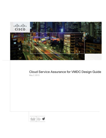
Table 3 - WAN-aggregation for Cisco vWAAS on Cisco UCS B-Series and Cisco UCS C-SeriesDeviceMax. optimized TCPconnectionsMax. recommendedWAN link [Mbps]Max. optimizedthroughput [Mbps]Max. core 02800For comprehensive sizing and planning, please work with your Cisco account team or Cisco partner.AppNavCisco Application Navigator (AppNav) technology enables customers to virtualize WAN optimization resourcesby pooling them into one elastic resource in a manner that is policy based and on demand with the bestavailable scalability and performance. It integrates transparently with Cisco WAAS physical and virtual networkinfrastructure and supports the capability to expand the WAN optimization service to meet future demands.The Cisco AppNav solution is comprised of one or more Cisco AppNav Controllers, which intelligently load sharenetwork traffic for optimization to a set of resource pools built with Cisco WAAS nodes. The Cisco AppNavControllers make intelligent flow distribution decisions based on the state of the WAAS Nodes currently providingservices.Figure 1 - WAAS AppNav ComponentsAppNav cWANWAAS NodeGroupWAAS NodeGroupWAAS NodeGroupAppNav ControllerAppNav Load SharingIntroduction1159WAAS NodeAugust 2014 Series5
A Cisco AppNav Controller (ANC) is a WAVE appliance with a Cisco AppNav Controller I/O Module (IOM) thatintercepts network traffic and, based on an AppNav policy, distributes that traffic to one or more WAAS nodes foroptimization. The ANC function is also available as a component of Cisco IOS-XE software running on the CiscoASR 1000 Series routers and the Cisco ISR 4451-X router. When the AppNav Controller is running as a routersoftware component, it is referred to as AppNav-XE.Reader TipSome Cisco product documentation may use different terminology. This guidereferences the most common terminology in use for consistency.Examples:AppNav Controller (ANC) AppNav Controller (AC)AppNav Controller group (ANCG) AppNav Controller group (ACG)Table 4 - Supported roles for Cisco WAVE appliances with a Cisco AppNav -APNV-10GEWAVE-594—AppNav ControllerWAVE-694WAAS NodeAppNav Controller—WAVE-7541WAAS NodeAppNav Controller—WAVE-7571WAAS NodeAppNav Controller—WAVE-8541WAAS NodeAppNav Controller—Tech TipThe WAVE-APNV-10GE is only available bundled with the WAVE-594 and redundantpower supply unit.A Cisco AppNav Controller group (ANCG) is a group of AppNav Controllers that share a common policy andtogether provide the necessary intelligence for handling asymmetric flows and providing high availability. Thegroup of all ANC and WN devices configured together as a system is referred to as an AppNav Cluster.Tech TipA Cisco AppNav-XE controller group must contain only routers of the same productfamily and model (Example: only Cisco ASR 1002-X routers, or only Cisco ISR 4451-Xrouters). The ANCG may contain up to four AppNav-XE routers.IntroductionAugust 2014 Series6
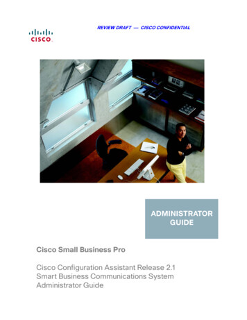
WAN Aggregation Design ModelsThere are three different design models for the WAN-aggregation site. The following table provides a briefsummary with more detail available in the specific sections for each design model.Table 5 - How to choose a WAN Aggregation design modelRequirementWAAS with WCCP designmodelAppNav Off Path designmodelAppNav-XE design modelAppNav IOMNot neededRequiredNot neededMix of different routerfamiliesSupportedSupportedAll routers in a controller group mustbe same product modelMaximum number ofANCs in an ANCGNot applicable84Intelligent load sharingBasic load sharing onlyFull AppNav policiesFull AppNav policiesWAAS node group with WCCPThe Cisco WAAS node group with WCCP design model has been the Cisco recommended design for manyyears prior to the introduction of AppNav. This design is widely adopted and is still currently supported by Cisco.The AppNav IOMs are not required and because the router redirection method is WCCP, this design allowsfor a mix of router product families. This design model is the recommended design model for remote-sitedeployments.The Cisco WAAS node group with WCCP deployment model uses a single group of two or more WAAS Nodesto provide WAN optimization. The total number of devices required is a minimum of two (for N 1 resiliency).The Cisco WAVE appliances or Cisco vWAAS instances connect to the distribution-layer switch. The connectionsto WAVE appliances use EtherChannel both for increased throughput and for resiliency. EtherChannel is a logicalinterface that bundles multiple physical LAN links into a single logical link. A vWAAS instance uses networkinterface card (NIC) teaming in order to provide resiliency. In both cases, the WAAS Nodes connect to the WANservices network that is configured on the distribution switch.The Web Cache Communication Protocol (WCCP) is a protocol developed by Cisco. Its purpose is totransparently intercept and redirect traffic from a network device to a WCCP appliance such as a Cisco WAVEappliance running Cisco WAAS.In this design model, WCCP is enabled on the Multiprotocol Label Switching (MPLS) CE and Dynamic MultipointVPN (DMVPN) routers. The WCCP redirect uses service groups 61 and 62 in order to match traffic forredirection. These service groups must be used in pairs: Service group 61 uses the source address to redirect traffic. Service group 62 uses the destination address to redirect traffic.This design uses WCCP 61 inbound on LAN-facing interfaces in order to match unoptimized data sourced fromthe data center that is destined for clients at the WAN remote sites. WCCP 62 is used inbound on WAN-facinginterfaces, matching optimized data sourced from the WAN remote sites. WCCP 62 is used outbound on LANinterfaces for DMVPN hub routers.The connections from the distribution switch to the WAN aggregation routers are routed point-to-point links. Thisdesign mandates the use of a negotiated-return generic routing encapsulation (GRE) tunnel from WN to router.When a design uses a GRE-negotiated return, it is not required that the WN and the WAN aggregation routersare Layer 2 adjacent.IntroductionAugust 2014 Series7
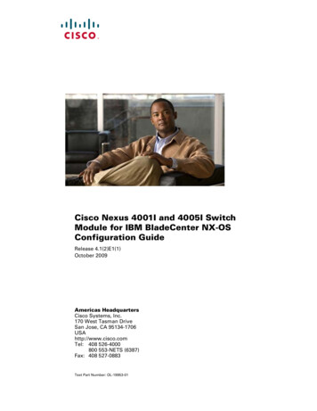
Figure 2 - WAAS node group with WCCP design modelWAAS Node GroupWANDistributionDMVPNHub RouterWCCP Inbound Redirect:WCCP 61 (from LAN)Internet EdgeWCCP 62 (from WAN)WCCP Outbound Redirect:DMVPNTunnelCE RoutersNegotiated GRE TunnelWANInternetWANDMVPN Tunnel1109WCCP 62 (from WAN)AppNav Off PathThe Cisco AppNav Off Path design model is the preferred model for new deployments.The Cisco AppNav Off Path design model logically inserts the ANCs between the redirecting routers and theCisco WAAS node group(s). WCCP is still used between the routers and the AppNav controllers, but the WCCPfunction is strictly limited to redirection and performs no load distribution. AppNav performs the intelligent loaddistribution.In this design model, WCCP is enabled on the Multiprotocol Label Switching (MPLS) CE and Dynamic MultipointVPN (DMVPN) routers. The WCCP redirect uses service groups 61 and 62 in order to match traffic forredirection, as discussed in the previous section: Service group 61 uses the source address to redirect traffic. Service group 62 uses the destination address to redirect traffic.Tech TipWhen using a Cisco AppNav Off Path deployment, it is possible to use just a singleWCCP service group (Example: service group 61) in order to provide WCCP redirectionfor both source and destination traffic. However, this design model continues to use apair of service groups for consistency and ease of migration.IntroductionAugust 2014 Series8
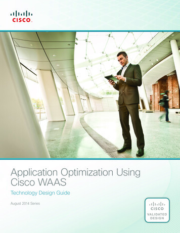
The connections from the distribution switch to the WAN aggregation routers are routed point-to-point links. Thisdesign mandates the use of a generic GRE tunnel between the ANCs and the routers. When a design uses ageneric GRE tunnel, it is not required that the ANCs and the WAN aggregation routers are Layer 2 adjacent.You may enable both the ANC and WN capability concurrently on a Cisco WAVE appliance when using the1-Gbps IOMs. This allows the device to perform dual roles.Figure 3 - AppNav off path design modelWAAS Node GroupsWANDistributionAppNavControllerGroupDMVPNHub RouterDMVPNTunnelWCCP Inbound Redirect:WCCP 61 (from LAN)Internet EdgeCE RoutersWCCP 62 (from WAN)WCCP Outbound Redirect:WANWANInternetWCCP 62 (from WAN)AppNav Load Sharing1107Generic GRE TunnelDMVPN TunnelAppNav-XEThe Cisco AppNav-XE design model allows you to deploy AppNav with an existing group of Cisco WAAS nodeswithout requiring the installation of IOMs. You are limited to up to four AppNav-XE Controllers, which must all bethe same router model. Also, the ANCG may not include IOM-based ANCs.The Cisco AppNav-XE deployment model uses an AppNav Controller running natively on the WAN-aggregationrouters. Traffic interception is accomplished by using service insertion on the routers’ WAN interfaces. WCCP isnot required for this deployment model, and the ANCs and the WAN aggregation routers are not required to beLayer 2 adjacent.IntroductionAugust 2014 Series9
Cisco AppNav performs the intelligent load sharing across the different Cisco WAAS node groups.Figure 4 - AppNav-XE design modelWAAS Node GroupsWANDistributionDMVPNHub RouterAppNavControllerGroupInternet EdgeCE RoutersDMVPNTunnelWANWANInternetDMVPN Tunnel1110AppNav Load SharingRemote SitesThe WAN optimization design for the remote sites can vary somewhat based on site-specific characteristics.Single router sites use a single (nonredundant) Cisco WAVE appliance or Cisco vWAAS instance. Similarly, alldual-router sites use dual WAVE appliances or vWAAS instances. The specifics of the WAAS sizing and formfactor primarily depend on the number of end users and bandwidth of the WAN links. Low bandwidth ( 2 Mbps)single-router, single-link sites can also use the embedded Cisco WAAS Express (WAASx) capability of therouter.There are many factors to consider in the selection of the WAN remote-site WAN optimization platform. Theprimary parameter of interest is the bandwidth of the WAN link. After the bandwidth requirement has been met,the next item under consideration is the maximum number of concurrent, optimized TCP connections. Additionaldetail on the Cisco WAVE and Cisco vWAAS sizing is provided in the following tables. The optimized throughputnumbers correspond to the apparent bandwidth available after successful optimization by Cisco WAAS.IntroductionAugust 2014 Series10
Table 6 - WAN remote-site Cisco WAVE appliances and WAAS ExpressDeviceMax. optimized TCPconnectionsMax. recommendedWAN link [Mbps]Max. optimizedthroughput E-694-16GB2500200450WAVE-694-24GB6000200500Note:1. Single-link design onlyTable 7 - WAN remote-site Cisco vWAAS on Cisco UCS E-SeriesDeviceMax. optimized TCPconnectionsMax. recommendedWAN link [Mbps]Max. optimizedthroughput 130080300vWAAS-25002500200400For comprehensive sizing and planning, please work with your Cisco account team or Cisco partner.The embedded Cisco WAASx provides a subset of the full set of WAAS capabilities available on the Cisco WAVEplatforms. The current WAASx software release is compatible with single-link WAN designs, cost-effective, andeasy to deploy. No design or architecture changes are required to enable this functionality on the router.Figure 5 - WAN remote-site—Cisco WAASx topologyWANRouter withWAASxAccessSwitchIntroduction1112WAAS InterfaceAugust 2014 Series11
The Cisco WAAS form factors for a WAN remote site include a Cisco UCS E-Series router module, CiscoServices-Ready Engine (SRE) router module and an external appliance. These variants all run the same WAASsoftware and are functionally equivalent. The primary difference is the method of LAN attachment for thesedevices: Appliance—Two interfaces (both external) SRE module—One internal interface (router-connected only), one external interface UCS E-Series module—One or two interfaces (both external)The approach for connecting the Cisco WAVE or Cisco vWAAS devices to the LAN is to be consistent regardlessof the chosen hardware form-factor. All connections are made using the external interfaces. The benefit of thismethod is that it is not necessary to create a dedicated network specifically to attach the WAAS devices, andthe Cisco UCS E-Series module, Cisco SRE module, and appliance devices can use an identical design. Theinternal interface of the SRE module is not used for this design, except for the initial bootstrapping of the deviceconfigurations. The internal interface of the UCS E-Series module is not used for this design, except for the initialbootstrapping and management of the device configurations.You must connect an external Ethernet cable from each Cisco SRE module for this solution. You must alsoconnect one or two external Ethernet cables from each Cisco UCS E-Series module for this solution.You should connect the Cisco WAAS devices to the data VLAN of the access switch in all flat Layer 2 designs.When the deployment uses a distribution-layer design, the Cisco WAAS devices should connect to the primarydata VLAN on the distribution switch.Figure 6 - Cisco WAAS topology--remote-site access-layer designSingle WAN Access-Layer ConnectionWANDual WAN Access-Layer ConnectionWANWAAS NodeWAAS NodeGroupTransitDataWireless DataVoiceWireless VoiceWCCP Inbound Redirect:DataWireless DataVoiceWireless VoiceWCCP 61 (from LAN)1113WCCP 62 (from WAN)Negotiated GRE TunnelIntroductionAugust 2014 Series12
Figure 7 - Cisco WAAS topology--remote-site distribution-layer designWANWAAS Node GroupWCCP Inbound Redirect:WCCP 61 (from LAN)Negotiated GRE Tunnel1114WCCP 62 (from WAN)Where possible, connect the Cisco WAVE appliances through both interfaces by using EtherChannel forperformance and resiliency. A Cisco vWAAS instance uses NIC teaming to provide resiliency.Cisco WCCP Version 2 is enabled on the WAN routers to redirect traffic to the Cisco WAAS appliances.The WCCP redirect uses service groups 61 and 62 in order to match traffic for redirection. These servicesgroups must be used in pairs: Service group 61 uses the source address to redirect traffic. Service group 62 uses the destination address to redirect traffic.This design uses WCCP 61 inbound on LAN-facing VLAN subinterfaces in order to match unoptimized datasourced from the clients and destined for the data center (or other remote sites). In all cases, WCCP 62 is usedinbound on WAN-facing interfaces in order to match optimized data sourced from the data center (or otherremote sites).Because the Cisco WAVE appliance is connected to the data VLAN, this design requires the use of a negotiatedreturn GRE tunnel from the Cisco WAVE appliances to the router. When using a GRE-negotiated return, you arenot required to create a new network on the routers specifically to attach the WAVE appliances.IntroductionAugust 2014 Series13
Deployment DetailsHow to Read CommandsT
Use Case: Optimization of Traffic Traversing the WAN Application optimization can boost network performance along with enhancing security and improving application delivery. Cisco WAN Optimization is an architectural solution comprising a set of tools and techniques that work together in a strategic systems approach to provide best-in-class WAN .