Transcription
5Image Quality Requirementsfor Digital Mammographyin Breast Cancer ScreeningMargarita Chevalier1, Fernando Leyton2,3, Maria Nogueira Tavares3,Marcio Oliveira3, Teogenes A. da Silva3 and João Emilio Peixoto41ComplutenseUniversity of MadridPortales University3Centro de Desenvolvimento da Tecnologia Nuclear4Instituto Nacional do Cáncer1Spain2Chile3,4Brazil2Diego1. IntroductionMammography is currently considered to be the best tool for early detection of breastcancer. The target groups of most of the population-based screening programmes arewomen aged between 50 and 65 years. A recent study has also shown mortality benefit inthe age group 40-49 (Hellquist, et al, 2010). Screen-film mammography has been to date thetraditional test for breast screening having been shown its efficacy in reducing breast cancermortality in large randomised trials (Duffy, et al, 2006). The potential advantages of digitalmammography over screen-film techniques have been the subject of several investigationswhich provides an improved diagnosis in dense breasts and an increase in breast cancerdetection rate (Pisano et al, 2006; Hendrick et al, 2010).Breast screening using X-ray mammography only confers a benefit on the screenedpopulation if it is able to detect breast cancer at an early stage, whereby the prognosis isimproved. This can only be achieved by having high quality breast images to assure asmuch as possible the detection of small and subtle lesions in the breast (Muller,1997;Karellas, 2004; Lewin, 2004; ICRU, 2009). High quality mammography must beachieved and maintained by applying rigorous and comprehensive quality assurance andcontrol programmes.The quality of the breast images depends critically on the design and performance of theradiographic unit, the image receptor, and on how that equipment is used to acquire andprocess the mammogram. The type of display and the conditions under which the image isviewed have an important effect on the ability of the radiologist to extract the informationrecorded in the mammogram. The diagnostic information is integrally related to the qualityof the image and higher image quality will result in more accurate diagnosis (Nishikawa,2004). The systematic monitoring of both image quality and radiation dose is needed towww.intechopen.com
116Imaging of the Breast – Technical Aspects and Clinical Implicationguarantee a constant high quality of the mammography examination (ICRU, 2009; Ng,2005). Conventional film/screen mammography is being gradually substituted by digitaltechnology in most countries. Consequently, there is an important activity related withdeveloping quality control protocols adapted to this new digital technologies (CEC,2006;SEFM, 2008;NHSBSP, 2009; IAEA, 2011).Data retrieved from programmes in the Netherlands (Beckers, 2003), Sweden (Leitz, 2001),Norway (Pedersen, 2000) and the UK (NHSBSP, 2003) show that the levels of DG in screenfilm mammography range between 0.8 and 2.5 mGy for a 5.3 cm compressed breastthickness. Thus, several national and international protocols have established an acceptedDG limit of 2.5 mGy for a 5.3 cm standard breast thickness. Data from a European survey(Report EUR 14821, 2001) on radiation doses developed in 56 mammography institutionsshowed DG values ranging from 1.0 to 3.0 mGy for 6.0 cm thick breasts. This value wasestablished from measurements using an acrylic simulator.This chapter is devoted to describe the relevant parameters and procedures for the qualitycontrol of digital mammography systems making the necessary distinctions among the twotechnologies (computed radiography (CR) and flat panel detectors (DR)).2. Detectors for digital mammography2.1 Flat panel Systems – DRFlat panel systems (DR) have an active matrix of electronic detectors where each elementabsorbs the radiation transmitted through mammary tissue, producing an electrical signalproportional to the intensity of the X-rays.2.1.1 Indirect capture of an imageIn the indirect capture of an image, a flat screen scintillator, a photodiode circuitry layer, and aTFT array are used (Fig. 1). Caesium iodide crystals (CsI(Tl)) are the scintillators usuallyemployed. CsI(Tl) crystals are structured in an array of thin needles that guide the light photonreducing the light diffusion within the scintillator layer. The light is captured by the elementsof the photodiode matrix (amorphous silicon), which converts the light into electrical current.These amorphous silicon sensors (a-Si) are connected to a matrix of thin-film transistors (TFT)which store the information of each pixel up to the moment of its reading by the scan circuit inthe detector (Vedantham, 2000; Suryanarayanan, 2004; Peixoto, 2009).2.1.2 Direct capture of an imageIn the direct capture mode, an amorphous selenium plate (a-Se) photoconductor is used toconvert the incident X-ray photons into electron-hole pairs (Yaffe, 1997, Peixoto, 2009). Eachcharge of the electron-hole pair created is attracted by the corresponding electrode under theaction of the strong electric field applied between the electrodes. The created charge isaccumulated and stored by a TFT matrix (Fig. 2).2.2 Computed radiography system – CRComputed radiography (CR) is a process comparatively similar to the conventional screenfilm system. The film is replaced by a plate (IP) made up of photostimulable phosphoruswww.intechopen.com
Image Quality Requirements for Digital Mammography in Breast Cancer Screening117Fig. 1. Indirect method of image acquisition with CsI(Tl)/a-Si. The CsI scintillators holdneedle structures and work as channels which guide the light perpendicularly to the surfaceof the photodiodes (Peixoto, 2009).Fig. 2. Method of direct acquisition of an image with a-Se (Peixoto, 2009).(PSP) which is introduced into a cassette of similar characteristics than the one used with thefilm.Inside the cassette, the photostimulable phosphorus plate is used to absorb and store theenergy of the X-ray transmitted through the breast, thus producing a ‘latent image’. Theenergy stored in the phosphorous plate is associated to the electrons raised to excited levelsof energy in which they hold trapped (“F-centre”). This is the non-observable electroniclatent image, where the number of electrons trapped is proportional to the number ofincident X-ray photons (Marcelino V.A. Dantas., 2010). As follows, the cassette is insertedinto the reading unit (Fig. 3). Inside this unit, the plate is scanned with a low energy intenselaser light ( 2 eV) which is highly focused. The electrons trapped in the phosphorusphotostimulable matrix (PSP) are stimulated by the laser energy, and a significant fractionwww.intechopen.com
118Imaging of the Breast – Technical Aspects and Clinical Implicationreturns to the lowest energy level with a simultaneous emission of a higher energy photostimulated luminescence (PSL) ( 3 eV). The intensity of the PSL, proportional to thenumber of electrons emitted, is captured by a light guide system near the IP (Fig. 4). Aphotomultiplier tube (PMT) at the output of the light guide amplifies and converts the PSLinto a corresponding output voltage (Rowlands, 2002; Dantas, 2010).Fig. 3. Image digitiser for CR Systems (Alvarenga, 2008).Fig. 4. Image acquisition for the CR system: (a) single reading; (b) double reading (Peixoto,2009).www.intechopen.com
Image Quality Requirements for Digital Mammography in Breast Cancer Screening119The residual latent image information is erased through an intense light which removes theelectrons not released by the laser stimulation, and the IP returns to the cassette “reset” andready to be reused.The diagram of the whole process involving the image acquisition with a CR system isshown in Fig. 5 (left).Fig. 5. Acquisition process, processing and visualisation of mammography images CR(Alvarenga, 2008).3. Parameters with the greatest impact on dose and image qualityThe objective of mammography is to provide the early detection of cancer, and therefore theimage quality is a fundamental aspect. The image with a suitable diagnostic-quality has tobe acquired with a radiation dose as low as possible. Nowadays, it is widely accepted thatmean glandular dose (DG) is the best indicator to estimate the risk associated with breastirradiation in mammography (see definition in SectionV). Both factors, image quality andDG, are depending on breast characteristics (glandularity and thickness), exposure factors(beam quality, exposure time and compression force), detector features and mammographysystem performance (automatic exposure control) and characteristics (geometry, focal spotsize).3.1 Characteristics of the breastBreast composition varies among women due to different proportion of glandular, fibrousand adipose tissue. The composition also changes with the age of the woman such that theproportion of adipose tissue increases with age.www.intechopen.com
120Imaging of the Breast – Technical Aspects and Clinical ImplicationDifferences among the x-ray attenuation properties of the different breast tissues can beobserved at the breast images. Glandular and fibrous tissues are visualised in mammographyas radio-opaque whereas the adipose tissues are observed as radio-lucent (dark). Therefore,given the same compressed breast thickness a dense breast (having a higher proportion ofglandular tissues) absorbs a higher amount of radiation than an adipose breast.The lesions of interest for diagnosis are microcalcifications, masses, asymmetries anddistortions of the breast architecture. Microcalcifications are small (100 µm) and “easily”detected regardless of breast density. The masses tend to have low contrast, making itdifficult to detect. Therefore, mammography must have - besides optimal resolution - goodcontrast, which makes visible those anatomic structures and pathological signs which havevery similar densities.3.2 The compression systemA proper compression of the breast is fundamental to provide a good quality image. Breastcompression brings the structures close to the detector enhancing sharpness, prevents breastmovement, reduces the breast thickness penetrated by X-rays and reduces the scatteredradiation. All these factors improve the contrast and even reduce the absorbed dose(Karellas, 2004). In addition, the exposure factors in modern mammography systems areautomatically selected in base of the compressed breast thickness. Quality controlprogrammes have to include procedures to verify the compression force and the accuracy ofthe breast thickness determined by the system.3.3 Automatic exposure controlIn mammography, the automatic exposure control (AEC) (also known as “photo timer”)cuts off the exposure when arrives to the AEC radiation sensor, which lies below the antiscatter grid and the image receptor, the necessary dose resulting in optimum optical densityor pixel value. The sensor can be placed at several positions (3 in most of the units) betweenthe thorax and the nipple in depending of the breast size.Flat panel detectors of digital mammography units operate as AEC sensors. In this case, theinformation can be derived from the whole area of the detector or from predefinedregions.The AEC of most modern mammography units uses the information associated with a preexposure to determine the attenuation of the breast. This information along with the breastthickness automatically detected (compressor) determines all the exposure factors(anode/filter, kV, mAs).The AEC is committed to provide images with an appropriate optical density,independently from the beam quality and the characteristics of the breast. Thus, there is aguarantee that the information will be registered in the linear region of the characteristiccurve of the film.In digital systems, the main role of the AEC is to assure that signal noise ratio (SNR) andcontrast noise ratio (CNR) are adequate throughout the image and that the dose valuescomply with recommendations.www.intechopen.com
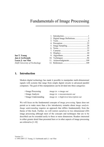
Image Quality Requirements for Digital Mammography in Breast Cancer Screening1213.4 X-ray spectrumFor both digital and screen-film detection techniques, the energy spectrum of the X-raybeam (including their filtering) is of a great concern when evaluating the performance of themammographic systems, demanding careful and accurate quality controls in a clinicalenvironment.Fig. 6. X-ray spectra for 30 kVp operating potential for Mo/Mo (a), Mo/Rh (b), Rh/Rh (c),and W/Rh (d) source/filter assemblies (NCRP 149, 2005).The attenuation coefficient of the glandular tissue is similar to that of the tumour tissuewhich makes difficult the visualization of smaller tumours; low energy X-ray beam isneeded to demonstrate the subtle density differences between non-calcified normal andabnormal tissues. X-ray tubes of mammography systems are equipped with specialwww.intechopen.com
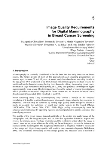
122Imaging of the Breast – Technical Aspects and Clinical Implicationanode/filter combinations, such as Mo/Mo or Mo/Rh, operating in the 25-35 kVp range.The spectra of several anode/filter combinations (Fig. 6) show the important proportion ofof X-rays characteristics (17.5 and 19.7 keV) from the molybdenum target and the strongsuppression of the spectrum at energies 20 keV because of the k-shell absorption edge ofthe molybdenum filter (Fig. 6a) or else higher than 23 keV because of the Rh filter (Fig. 6b).The characteristics of the new digital detectors make it possible to use other anode/filtercombinations such as Rh/Rh (Fig. 6c), W/Rh (Fig. 6d), W/Ag and W/Al which have someadvantages for imaging dense or thick breasts. In addition, the breast doses associated withthese combinations are lower than those delivered with Mo/Mo or Mo/Rh.The adequate selection of the spectrum (beam) may reduce the dose values above 20%(Young, 2006; Dance, 2000; Riabi, 2010). The threshold value for breast thickness where thespectrum is changed depends on the AEC calibration which is performed by technicalservices who install the equipment (which should be done together with those medical staffwho use the equipment). The correct selection of the X-ray beam will strongly influence thedose and image quality.4. Image quality in mammographyImage quality is a fundamental concept for the control and optimisation of mammography; itaims to improve the early detection of cancer and other pathological lesions in the breasts. Theimage quality can be quantified by measuring the contrast noise ratio, the signal noise ratio,the modulation transfer function (MTF) (spatial resolution), the noise, the uniformity andvarious artefacts such as the ghost image. In order to assess these physical parameters,phantoms and more specific devices are needed to perform quality control in mammography.The current trend is to utilise a contrast-detail phantom (CDMAM) which permits theassessment of the image quality as a function of the contrast threshold associated with thecircular objects of different diameters and thickness (SEFM, 2008). The “clinical ”assessment ofthe image quality is better performed by means of the receiver operating curve (ROC)methodology. Unfortunately, this type of analysis is far too complex and is time consuming. Inaddition, it is required a database with too many images, which makes its application difficultin the clinical practice of routine image quality control (NCRP, 2005).4.1 MTFThe modulation transfer function (MTF) is a quantitative and objective measurement of theimage quality that can be provided by a system. MTF gives information about themagnitude of the object contrast which is transferred to the image as a function of the spatialfrequency. The low spatial frequencies correspond to rough details, whereas the high onesdefine the fine details or the edges of the structures. For example, an MTF with a value of 0.5for a determined frequency means that the inherent modulation (contrast) of the object willdiminish at 50% given the limitations of the image system (ICRU, 2009) (Fig. 7).In practice, the MTF is determined through the Fourier transform of the line spread function(LSF), which is obtained through the differentiation of the edge response (ESF).Spatial resolution is expressed in terms of spatial frequency, which in turn is associated witha MTF value.www.intechopen.com
Image Quality Requirements for Digital Mammography in Breast Cancer Screening123Fig. 7. Modulation transfer function of mammography systems (ICRU, 2009).4.2 NoiseThe main component of noise in radiographic images is the quantum noise, which isassociated with the statistical fluctuations in the photons’ fluence on the detector and withthe random variations in the absorption. The simplest way to define the noise is through ameasurement of the standard deviation (sd) of the number of photons absorbed (N) in aregion of the detector. This figure complies with Poisson statistics, and therefore sd N0.5(i.e., the sd is related to the square root of the Kerma) (Chevalier, 2010).The structural noise in the digital detectors emerges mainly from the lack of homogeneity inthe sensitivity of the elementary detectors (i.e., from the fixed spatial variation of the imagedetecting structure), which means that it is also proportional to the dose. Moreover, thisnoise causes the appearance of a structured background in the image, which is usuallyremoved through the flat field techniques. These techniques include the creation of acorrective mask from a direct and uniform image of the X-ray beams (Chevalier, 2010).In digital systems, what has to be added to these two types of noise is the electronic one,which emerges from the electronic readout outside the pixels and in the amplification of thesignal and which does not depend on the dose. The electronic noise owes essentially to thedark noise in the detectors and decreases if the temperature of the surroundings is loweredor reduced. Therefore, the digital equipment has to operate in temperatures at intervalsbetween 20-30 ºC.4.3 UniformityThe initial operation which usually occurs is a "flat-field", a correction of the uniformity ofgain. The non-uniformity of the sensitivity of the detector is corrected through a gain mapand is also used to correct all the images acquired. Moreover, if an element of a single (pixel)detector is defective its signal can be replaced with a reasonable combination of adjacentdetector signals. This is acceptable if the defective detectors are isolated and only few ofthem are faulty. Detectors of the CR type presents a lack of uniformity due to the heal effectthat is very depending on the X-ray unit.www.intechopen.com
124Imaging of the Breast – Technical Aspects and Clinical Implication4.4 ArtefactsArtefacts are undesirable characteristics which are not related to the mammary anatomicstructures of a radiographic image. They can hinder the image by hiding or simulate a lesionon detection.Artefacts can be caused by the source of X-rays, the beam filter, the compression device,breast support, grid, and flaws in processing, amongst others. In digital mammography,besides the sources just cited, the non-uniformity in the response of the elemental detectorsmay also generate artefacts, owing to the results of an inadequate flat-fielding. Anotherdrawback in the digital system is the presence of reminiscent images (ghost images),resulting from previous exposures (ICRU, 2009). The latest appears more often with CRsystems or aSe based flat panel detectors.5. Dosimetry in mammographyOne of the pillars underpinning the analysis of the risks-benefits of mammography is theaccurate knowledge of the imparted doses, since it is well-established that there is anassociation between breast dose and the increased incidence of breast cancer. Assessmentsof breast doses are particularly important in breast screening programmes in which largegroups of asymptomatic women undergo mammographic examinations. As in otherradiological examinations, dose values are indicative of the diagnostic adequacy of themammography technique selected in clinical practice. In addition, knowledge of dose valuesis essential for optimisation strategies developed to minimise doses while maintaining thenecessary image quality.The X-ray spectrum in mammography is of low energy and the depth dose within the breastdecreases rapidly. Due to this, it is important to use a dosimetric quantity which gives ameasure of the dose to the whole organ. Glandular tissue is the most vulnerable in the breastas compared to adipose, skin and areolar (nipple) tissues (Hammerstein et al., 1979). Atpresent, it is widely accepted that mean glandular dose (DG) is the most appropriatedosimetric quantity to predict the risk of radiation carcinogenesis. Therefore, this quantityhas been recommended by several national and international organisations (NCRP, 1986;IPSM, 1989; IAEA, 2007) and it is the quantity used in many national protocols formammographic quality assessment (CEC, 1996, 2006; ACR, 1999; IAEA, 2007). The factorsthat affect DG are the X-ray beam quality and breast thickness and composition. These twolatter parameters have a larger variability than the former, varying both within and betweenpopulations, and the latter with women’s age as well. Even when the average glandularitywould be the same, its distribution is unpredictable and changes from breast to breast.Direct measurements of DG are not possible for individual breasts and, therefore, DG isderived from the entrance surface dose (or a related quantity) using adequate conversionfactors (ICRU, 2005; NCRP, 2004). These factors were initially measured (Hamerstein, 1979;Stanton, 1984) and further calculated by means of Monte Carlo techniques (Rosenstein, 1980;Dance, 1990, 2000, 2009; Wu et al, 1991, 1994; Klein et al., 1997; Boone et al., 2002). This latterapproach allows for the possibility of estimating conversion factors for a wide range ofinput spectra and breast features. Differences among the conversion factors (cG) obtained byseveral authors mainly arise from differences in breast model geometry, mammographic X-www.intechopen.com
Image Quality Requirements for Digital Mammography in Breast Cancer Screening125ray spectral data, photon interaction cross-sections and Monte Carlo codes. Other importantfactors affecting the calculations are the mammography system’s characteristics and theimaging system components and geometry. The differences in cG values quoted by differentauthors were as high as 15-16% (Klein, 1997; ICRU, 2005; Dance 2000).The breast model most commonly adopted (Fig. 8) has a central region consisting of ahomogeneous mixture of adipose and glandular tissue surrounded by a layer at all sides,except for the one corresponding to the chest wall representing the skin. It is assumed thatthe breast is firmly compressed by a polycarbonate compression paddle. The percentage ofbreast glandularity is defined as the fraction by weight of glandular tissue at the centralregion (without skin). Most authors employ the elemental tissue composition published byHammerstein et al. (1979).Initially, it was assumed that a 50:50 mixture of adipose and glandular tissues wasrepresentative of a typical breast (Hammerstein, 1979). On this basis, phantoms of severalthicknesses were constructed assuming this “standard” composition with the aim offacilitating DG estimates in the practice. This assumption implied that the fraction ofglandular tissue was independent of compressed breast thickness. On the basis of this data,the standard “phantom” was defined as a 4.5 cm thickness of PMMA, representing the“standard breast” (4 cm thick and 50%/50% glandular/adipose tissue) (IPEM, 1989; CEC,1996). Data indicating that the composition of the average compressed breast deviates fromthe 50:50 composition has been published (Geise, 1996; Klein et al., 1997; Young et al., 1998;Chevalier, 1998; Beckett, 2000; Zoetelief et al., 2006). In addition, it was found that breastglandularity decreases when the compressed breast thickness increases. In some of theseworks it is also determined that the equivalent thickness of PMMA gives the same incidentair kerma at its upper surface as for that of a breast of a specified thickness and composition(Geise, 1996; Dance et al., 2000, 2009; Kruger, 2001; Argo, 2004).Fig. 8. Breast model geometry. The rectangular section represents a vertical cross-sectionthrough the breast coplanar with the focal spot of the X-ray tube. The D-shape sectionrepresents the breast in craniocaudal projection. The shaded and outer regions represent,respectively, the breast parenchyma and the skin (0.5 cm of adipose tissue). In the work ofDance (2009) it is used as a voxelised breast model.5.1 Practical issuesDG is generally calculated through the following relationship (ICRU, 2005):www.intechopen.com
126Imaging of the Breast – Technical Aspects and Clinical ImplicationDG cG K a ,i(1)where Ka,i represents the incident air kerma (without backscatter) and cG is the appropriateconversion factor. The incident air kerma is the air kerma free in the air (withoutbackscatter) at the central axis of the incident X-ray beam at the skin-entrance plane whichyields the desired image optical density (screen-film mammography) or signal:noise ratio(digital mammography).5.1.1 Determination of the incident air kermaTwo approaches have been used to determine the incident air kerma, Ka,i. In the Europeanand IAEA approach (CEC, 1996, 2006; IAEA, 2007), this quantity is calculated from themeasured value of the X-ray tube output, Y(d), in terms of air kerma per tube-currentexposure-time product (mGy/mAs), measured at a distance d from the focal spot of themammography unit. The value of Ka,i at the focus to surface distance for the phantom or forcompressed breast (d’) is determined as follows: d K a ,i Y ( d )Pit ' d 2(2)Where Pit is the mAs employed for a given exposure of the compressed breast or phantom,which is determined from the AEC post-exposure readout. The tube output has to bemeasured using an ionisation chamber with a flat energy response (CEC, 1996; ICRU, 2009)and conveniently calibrated for the mammography beam qualities. The ionisation chamberis placed at 6 cm from the chest wall and laterally centre. The distance d is usually fixed at4.5 cm above the breast support. The compression plate should be about 10 cm above thechamber so as to avoid backscatter effects.Wu, 1991DGNDGNg c sDance, 2009cGp gDance, 2000UnitsBreastcomposition(% glandulartissue)Breast g.mixture.50%Homog.mixture0% - 100%Homog.mixture0% - 100%SpectraTube voltage(kV)Source imagedistanceCompressorGridImage receptorWu, 1994Homogeneous mixture.100%; 50%; 0%Dance, 19903–8Mo/Rh;Rh/RhMo/ Mo10 – 352–82 – 112 – AgW/Al23 – 5025, 26, 28, 30, 3225 - 4060 cm---------g c sIn place compressing the breast----In placeYes (screen)Yes (screen)65In placeYes (screen)Table 1. Important parameters considered by Dance and Wu for the calculation of theconversion factors using Monte Carlo techniques.www.intechopen.com
Image Quality Requirements for Digital Mammography in Breast Cancer Screening127In the ACR approach (ACR, 1999), Ka,i is directly measured by placing the ionisationchamber adjacent to the ACR phantom at the level of the entrance surface of the phantom.The chamber is positioned at 4 cm from the chest wall. The compressor plate is locatedabove the phantom and the chamber. The exposure conditions are those used clinically for a4 cm compressed breast.Ka,i can be also measured using TLD dosimeters (ACR, 1999; CEC, 1996) placed on theentrance surface of the phantom or breast. The TLDs have to be calibrated in terms of airkerma free-in-air against a suitable ionisation chamber and dosimeter. Hence, the entrancedose measured by TLDs placed on the phantom or patient surface includes backscatter.Measurements performed with TLD dosimeters are influenced by many factors, includingthe performance of the instrument and those related to procedure of dosimeter preparationand handling. In addition, TLDs’ response dependence of scatter gives rise tounderestimations of Ka,i in a magnitude that is dependent on the dosimeter's thickness andthe relative amount of backscatter radiation (Dance at al., 1999). Another factor that limitsthe use of TLD dosimeters is related with its visibility in the breast image. It isrecommended that they be positioned on the upper inner quadrant of the breast so as tominimise interference with breast tissues.5.1.1.1 Mean glandular dose (DG) estimatesThe ACR protocol adopted the cG values calculated by Wu (1991, 1994; Sobol, 1997). TheEuropean and the IAEA protocols (CEC, 1996, 2006; IAEA, 2007) recommended the use ofthe cG values from Dance (1990; 2000; 2009). Fig. 8 and Table 1 summarise the details usedby both authors to perform the Monte Carlo calculations. The cG values depend on the beamquality (half value layer (HVL)), breast thickness and breast composition. It is important tomeasure HLV and compressed breast thickness with accuracy in order to minimise theerrors in the DG estimate. Narrow beam geometry is recommended for HVL measurementswith the aim of reducing the influence of scattered radiation (IPEM, 2005; IAEA, 2007). Inaddition, Al filters of high purity ( 99%) should be used and the compressor plate should bein place during the measurements. Errors in the compressed breast thickness measurementare due to the compressor plate which can bend and deform considerably. Several authorshave proposed methods to gain accuracy in these measurements (Burch, A, 1995; Maria S.Nogueira., 2011).DG values derived from phantom measurements are useful for 1) simplifying the follow-upof the mammography system’s performance, 2) comparing with references or limitingvalues allowing the checking of the compliance of the equipment with recommendations, 3)checking if the exposure factors selected by the mammography system are suitable in termsof radiation dose, 4) fo
guarantee a constant high quality of the mammography examination (ICRU, 2009; Ng, 2005). Conventional film/screen mammography is being gradually substituted by digital technology in most countries. Consequently, there is an important activity related with developing quality control protocols adapted to this new digital technologies (CEC,2006;