Transcription
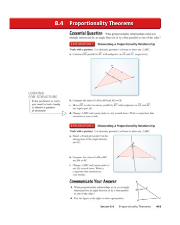
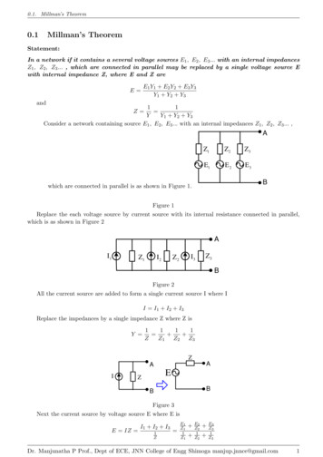
0.1. Millman’s Theorem0.1Millman’s TheoremStatement:In a network if it contains a several voltage sources E1 , E2 , E3 . with an internal impedancesZ1 , Z2 , Z3 . , which are connected in parallel may be replaced by a single voltage source Ewith internal impedance Z, where E and Z areE E1 Y1 E2 Y2 E3 Y3Y1 Y2 Y3and11 YY1 Y2 Y3Consider a network containing source E1 , E2 , E3 . with an internal impedances Z1 , Z2 , Z3 . ,Z AZ1Z2Z3E1E2E3Bwhich are connected in parallel is as shown in Figure 1.Figure 1Replace the each voltage source by current source with its internal resistance connected in parallel,which is as shown in Figure 2AI1Z1I2I3Z2Z3BFigure 2All the current source are added to form a single current source I where II I1 I2 I3Replace the impedances by a single impedance Z where Z isY 1111 ZZ1 Z2 Z3ZAAIEZBBFigure 3Next the current source by voltage source E where E isE IZ I1 I2 I31Z E1Z11Z1 E2Z21Z2 E3Z31Z3Dr. Manjunatha P Prof., Dept of ECE, JNN College of Engg Shimoga manjup.jnnce@gmail.com1
0.1. Millman’s TheoremE E1 Y1 E2 Y2 E3 Y3Y1 Y2 Y3Y 1111 ZZ1 Z2 Z3andY Y1 Y2 Y3Dr. Manjunatha P Prof., Dept of ECE, JNN College of Engg Shimoga manjup.jnnce@gmail.com2
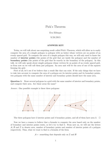
0.1. Millman’s TheoremFigure 52019-JULLY State and explain Millman’s theorem.The current through (6 j8)Ω, impedance is2019-JAN For the circuit shown in Figure 4 findthe current through (6 j8)Ω, impedance usingMillman’s theorem.10 415 120-j10 06 j8 415 00j10 415 2400Figure 4Solution:Y1 Y2 Y3 Y1135E Z ZL10 6 j811351135 16 j817.88 26.56 63.47 26.56I 11 0.1Z11011 j0.1Z2j1011 j0.1Z3 j10———————2018-JULY Using Millman’s theorem find currentthrough RL for the circuit shown in Figure 6.2Ω4Ω5Ω - 20 V - 40 V - 50 VILR L 9.4ΩFigure 6Solution:Y1 Y1 Y2 Y3 0.1 j0.1 j0.1 0.111 10ΩZ Y0.1Y2 Y3 11 0.5Z1211 0.25Z2411 0.2Z35E1 Y1 415 0.1 41.5E2 Y2 415 120 j0.1 415 120 0.1 90Y Y1 Y2 Y3 0.5 0.25 0.2 0.95 41.5 30 36 j20.75E3 Y3 415 240 j0.1 41.5 330Z 36 j20.75E1 Y1 E2 Y2 E3 Y3Y1 Y2 Y341.5 36 j20.75 36 j20.75 0.1113.5 0.1 1135E 11 1.052ΩY0.95E1 Y1 E2 Y2 E3 Y3Y1 Y2 Y320 0.5 40 0.25 50 0.2 0.9530 0.95 31.57E Millman’s equivalent circuit is is as shown in FigureMillman’s equivalent circuit is is as shown in 7.Figure 5.10Ω6Ωj8Ω1136 00IL1.052Ω - 31.57 VR L 9.4ΩFigure 7Dr. Manjunatha P Prof., Dept of ECE, JNN College of Engg Shimoga manjup.jnnce@gmail.com3
0.1. Millman’s Theorem—————2014-JULLY Using Millman’s theorem find thecurrent IL through RL for the network shown inFigure 10.The current IL through RL is31.5731.57 Z ZL1.052 9.4 3.02AIL ———————2017-JAN Apply Millman’s theorem to find VO andIO for the circuit shown in Figure 8.-j5Ω10Ωj5Ω2Ω -100 V -j100 V --j100 V2Ω3Ω4Ω - 10 V - 20 V - 30 VVoIoSolution:11 0.5Z1211 0.33Z2311 0.25Z34Y1 Solution:Y2 Y3 11 0.1 Z11011 j0.2Z2 j511 j0.2Z3j5R L 10ΩFigure 10Figure 8Y1 ILY2 Y3 Y Y1 Y2 Y3 0.5 0.33 0.25 1.0833Y Y1 Y2 Y3 0.1 j0.2 j0.2Z 0.1Z 11 10ΩY0.1E1 Y1 E2 Y2 E3 Y3Y1 Y2 Y3100 0.1 j100 j0.2 j100 j0.2 0.1 30 0.1 300E 11 0.923ΩY1.0833E1 Y1 E2 Y2 E3 Y3Y1 Y2 Y310 0.5 20 0.33 30 0.25 1.083319.16 1.0833 17.689E Millman’s equivalent circuit is is as shown in FigureMillman’s equivalent circuit is is as shown in Figure 11.7.0.923Ω10Ω2Ω-300 Vo - 17.686 VILR L 10ΩIoFigure 11Figure 9The current IL through RL isIL 300 300 Z ZL10 2 25AVO 25 2 50VThe current IL through RL isE17.689 Z ZL17.689 10 1.6191AIL ———————–Dr. Manjunatha P Prof., Dept of ECE, JNN College of Engg Shimoga manjup.jnnce@gmail.com4
0.1. Millman’s Theorem2013-JAN Using Millman’s theorem find the currentIL through RL for the network shown in Figure 12.4Ω4Ω4Ω 4V 2V - 10 VIL1Ω2Ω3Ω - 1 V - 2 V - 3 VR L 10ΩY1 Solution:Y1 1Z1Y2 Y3 Y2 Y3 YY Y1 Y2 Y3 0.25 0.25 0.25 0.75Z E Y1 Y2 Y3 1 0.5 0.333 1.833Z 11 1.333ΩY0.75E1 Y1 E2 Y2 E3 Y3Y1 Y2 Y3 4 0.25 2 0.25 10 0.250.7510.751.3331Z111 1Z1111 0.5Z2211 0.333Z33Y1 11 0.25Z1411 0.25Z2411 0.25Z34Y1 R L 10ΩFigure 14Figure 12Solution:IL11 0.5454ΩY1.833E1 Y1 E2 Y2 E3 Y3Y1 Y2 Y31 1 2 0.5 3 0.333 0.3331 1.833 1.636VE Millman’s equivalent circuit is is as shown in FigureMillman’s equivalent circuit is is as shown in Figure 15.13.1.333Ω - 1.333 VILR L 10ΩFigure 13The current IL through RL isE1.333 Z ZL1.333 10 0.1176AIL 0.5454Ω - 1.63 VILR L 10ΩFigure 15The current IL through RL is1.636E Z ZL0.5454 10 0.1552AIL 13-JULY Using Millman’s theorem find the 2012-JULY Using Millman’s theorem find thecurrent IL through RL for the network shown in current IL through RL for the network shown inFigure 14.Figure 16.Dr. Manjunatha P Prof., Dept of ECE, JNN College of Engg Shimoga manjup.jnnce@gmail.com5
0.1. Millman’s Theorem4Ω5Ω - 20 V 40 V - 50 Vj20ΩERIL2Ω- R L 9.4ΩEY- -j20ΩSFigure 16Solution:20ΩEB11 0.5Z1211 0.25Z2411 0.2Z35Y1 Y2 Y3 - Figure 18Solution:Y1 Y2 Y Y1 Y2 Y3 0.5 0.25 0.2Y3 0.95Z 11 1.052ΩY0.95E1 Y1 E2 Y2 E3 Y3Y1 Y2 Y320 0.5 40 0.25 50 0.2 0.9530 0.95 31.57VY11 j0.05Z1j2011 j0.05Z2 j2011 0.05Z320 Y1 Y2 Y3 j0.05 j0.05 0.05 0.0511 20ΩY0.05E1 Y1 230 j0.05 j11.5Z E E2 Y2 230 120 j0.05E2 Y2 230 120 0.05 90 11.5 30E3 Y3 230 120 0.05 j11.5E3 Y3 230 120 0.05 11.5 120Millman’s equivalent circuit is is as shown in Figure17.1.052Ω - 31.57 VILR L 9.4ΩE Figure 17The current IL through RL is31.57E Z ZL1.052 9.4 3.02A E1 Y1 E2 Y2 E3 Y3Y1 Y2 Y3 j11.5 11.5 30 11.5 1200.05 j11.5 9.95 j5.75 5.75 j9.950.054.2 j7.38.42 60 0.050.05168.4 60VMillman’s equivalent circuit is is as shown in Figure19.IL 168.4 60 V20Ω- ———————–2012-JAN Using Millman’s theorem determinevoltage VS of the network shown in Figure 18 giventhat ER 230 0 V, EY 230 120 V EB 230 120 V .Dr. Manjunatha P Prof., Dept of ECE, JNN College of Engg Shimoga manjup.jnnce@gmail.com6
0.1. Millman’s TheoremFigure 19Y————————Using Millman’s theorem determine current flowingthrough (4 j3) Ω of the network shown in Figure20 Y1 Y2 Y3 0.12 j0.16 0.37 j0.11 0.386 16.56A5 30 10Ω4Ω10 30 j10Ωj3Ω3ΩZ 4 30 11 2.6 16.56ΩY0.386 16.565Ω-j4ΩE1 Y1 141.14 75 0.0707 45 B 9.978 30 8.641 j4.989Figure 20Solution:Replace the current source and parallel resistance by a voltage sourceE2 Y2 5 30 0.2 1 30 0.8666 j0.5E3 Y3 20 83.13 0.2 53.13 4 30 3.464 j2Z1 10 j10 14.14 45 ΩE1 10 30 14.14 45 141.4 75 SimilarlyZ3 3 j14 5 53.13 ΩE3 4 30 5 53.13 20 83.13 The modified network as shown in Figure 21A5 30 141.4 75 20 83.13 4ΩE1 Y1 E2 Y2 E3 Y3Y1 Y2 Y38.641 j4.989 0.8666 j0.5 3.464 j2 0.386 16.5612.971 j3.48913.432 15 0.386 16.560.386 16.56 168.4 60VE 5 53.13 Ω14.14 45 Ωj3Ω5ΩMillman’s equivalent circuit is is as shown in Figure19.BAFigure 21Y1 Y1 Y2 Y3 11 0.0707 45 Z114.14 45 0.05 j0.0511 0.2Z2511 0.2 53.13 Z35 53.13 0.12 j0.162.591 16.56 Ω4Ω25 34.45 j3ΩBFigure 22Dr. Manjunatha P Prof., Dept of ECE, JNN College of Engg Shimoga manjup.jnnce@gmail.com7
0.2. Thevenin’s and Norton’s Theorems0.20.2.1Thevenin’s and Norton’s TheoremsThevenin’s TheoremStatement:Any linear, bilateral network with two terminals can be replaced by a single voltage sourceET H in series with an impedance ZT H , where the ET H is an open circuit voltage at theterminals and an impedance ZT H is the equivalent impedance as viewed from the terminalsinto the network.ZTHAAAny Linear,bilateraltwoterminalnetworkILILE THZLBZLBFigure 23Proof:Consider a network as shown in Figure 24. Thecurrent in the terminal AB is2Ω Step 2: Determine the Tehevenin’sImpedance8ΩA4Ω10 V -2Ω8ΩILAR L 10Ω4ΩBFigure 24BFigure 26VV 10 V 02418V [0.5 0.25 0.0556] 5V IL Step 1:VoltageZTH 9.333Ω5 6.0260.80566.026 0.3448A18ZT H 8 2 4 9.333Ω2 4 Step 3: Tehevenin’s Equivalent CircuitDetermine the Open CircuitZTH 9.333ΩA2Ω8ΩA10 V -i1 E 6.667VTH4ΩBBFigure 27Figure 25 Step 4: Current through IL is6i1 10 0i1 1.666AET H 1.666A 4 6.667VIL ET H6.667V 0.344 AZT H ZL9.333 10Dr. Manjunatha P Prof., Dept of ECE, JNN College of Engg Shimoga manjup.jnnce@gmail.com8
0.2. Thevenin’s and Norton’s TheoremsZTH 9.333ΩAILR L 10ΩETH 6.667V -BFigure 280.2.2Norton’s TheoremStatement:Any linear, bilateral network with two terminals can be replaced by a single current sourceIN in parallel with an impedance ZN , where the IN is an short circuit current through theterminals and an impedance ZN is the equivalent impedance as viewed from the terminalsinto the network.Any gure 290.2.3Maximum Power Transfer TheoremStatement:In Any linear, bilateral network maximum power is delivered to the load RL by the sourcewhen the load resistance RL is equal to the Thevenin’s resistance RT H .Any Linear,bilateraltwoterminalnetworkZTHAAILILZLBZLE THBFigure 30Dr. Manjunatha P Prof., Dept of ECE, JNN College of Engg Shimoga manjup.jnnce@gmail.com9
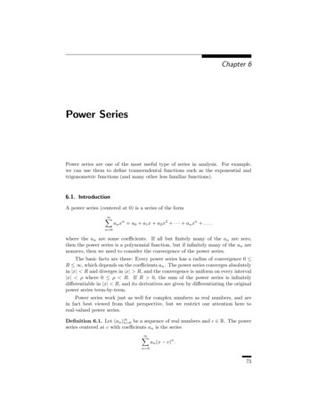
0.2. Thevenin’s and Norton’s TheoremsQ 1) Find the Thevenin and Norton equivalent forthe circuit shown in Figure 31 with respect terminalsA-B4Ω6Ω4Ω6Ω4Ω4Ωx12Ω y12Ω z96 V -AAISCIL96 V -12Ω20Ω12ΩBFigure 34B18x 12y 0z 96Figure 31 12x 28y 12z 0Solution:Determine the Thevenin voltage VT H . Apply KVLfor the circuit shown in Figure 32.4Ω6Ω96 V -x4Ω12Ω yA12ΩVOC0x 12y 16z 0By Solvingx 9.212A y 5.818A z 4.36AISC IN z 4.36AB8.8ΩAAFigure 3238.4 -4.36 A8.8Ω18x 12y 96 12x 28y 0BBThevenin’s EquivalentNorton’s EquivalentBy SolvingFigure 35x 7.467A y 3.2ACurrent through RL isVOC 7.467 12A 38.4VIL 38.4VOC 1.33ARL20 8.8Power through isZT H [(6 12) 4] 12 4 [4 4] 12 4 8 12 4 4.8 4PL IL2 RL (1.33)2 20 35.56WMaximum power is RL is 8.8ΩIL 6Ω4Ω4ΩAVOC38.4 2.18ARN RL8.8 8.8PL IL2 RL (2.18)2 8.8 41.856W—————–12Ω12ΩRTHBFigure 33To determine the short circuit current Apply KVLfor the circuit shown in Figure 34Dr. Manjunatha P Prof., Dept of ECE, JNN College of Engg Shimoga manjup.jnnce@gmail.com10
0.2. Thevenin’s and Norton’s TheoremsQ 2) Find the Thevenin and Norton equivalent forFigure 39the circuit shown in Figure 36 with respect terminals Q 3) Find the Thevenin and Norton equivalent forA-Bthe circuit shown in Figure 40 with respect terminals4Ω1ΩA-BAIL32 V -12Ω2 10 ARL6Ω2AIL50 V -5 RL10 3 BBFigure 36Solution:Figure 40Determine the Thevenin voltage VT H . Apply KVLSolution:for the for the circuit shown in Figure 37.Determine the Thevenin voltage VT H . Apply theKVL for the circuit shown in Figure 41.y 2A15x 5y 5016x 12y 32 5x 10y 016x 24 3232 24 0.5Ax 16VOC 12[0.5A ( 2)].5A 3 30V4Ω32 V -x1Ω12ΩBy Solvingx 4A y 2AVOC 2A 3 6Vy50 V -VOC2A2 10 A5 yxA3 VOCBBFigure 41Figure 37ZT HZT H (4 12) 1 [3.33 2] 3 3 1 4Ω 5.33 3 1.92Ω1Ω4Ω [(10 5) 2] 3A10 2 A12ΩRTH5 3 RTHBBFigure 384ΩFigure 42AADetermine the short circuit current by ApplyingKVL for the circuit 4330 V -7.5 A4Ω15x 5y 50 5x 7y 0BThevenin’s EquivalentBNorton’s EquivalentBy Solvingx 4.375A y 3.125ADr. Manjunatha P Prof., Dept of ECE, JNN College of Engg Shimoga manjup.jnnce@gmail.com11
0.2. Thevenin’s and Norton’s TheoremsVoltage across AB VOC VT H isISC IN y 3.125A50 V -10 2 x5 yVOCAISC3 6i 6 2 12V2i16Ωi120 V -B10Ω- i6ΩAVOCFigure 43B1.92 A6A3.125A -1.92 Figure 46When dependant voltage sources are presentthen Thevenin Resistance RT H is calculatedby determining the short circuit current atterminals AB:Thevenin’s Equivalent20 V -Current through RL isi1x6Ω y6VOC 0.503ARL1.92 10AISCBFigure 47Power through isPL IL2 RL (0.503)2 10 2.53WMaximum power is RL isIL 10Ω- Norton’s EquivalentFigure 44IL 2i16ΩBBx y i1KVL for loop xVOC6 1.5625ARN RL1.92 1.92PL IL2 RL (1.5625)2 1.92 4.68W12x 2i1 6y 20 012x 2(x y) 6y 2010x 4y 20—————–Q 4) Find the Thevenin and Norton equivalent for KVL for loop ythe circuit shown in Figure ? with respect terminalsa-b 6x 16y 02i16Ω6x 16y 010Ω- 20 V -Ai1Solving the following simultaneous equations6Ω10x 4y 20BFigure 456x 16y 0x 2.353 y 0.882Solution:ISC y 0.882ADetermine the Thevenin voltage VT H . Apply KVLThevenin’s resistance isfor the circuit shown in Figure 46.By KVL around the loop12VT HRT H 13.6ΩI0.882SC6i 2i 6i 20 010i 20i 2AThevenin and Norton equivalent circuits as shownin Figure 48Dr. Manjunatha P Prof., Dept of ECE, JNN College of Engg Shimoga manjup.jnnce@gmail.com12
0.2. Thevenin’s and Norton’s Theorems13.6Ω AAterminals AB. Apply KVL for loop x6x 2ia 12 012 V -0.882 A6x 2x 1212x 3A4ia x 3A13.6ΩBBThevenin’s EquivalentNorton’s EquivalentApply KVL for loop yFigure 48—————————Q 5) Find the Thevenin and Norton equivalent forthe circuit shown in Figure 49 with respect terminalsa-b6Ω3Ω3y 2ia 03y 2( 3) 0 6y 2A3Short circuit current ISCAISC y 2AThevenin resistance is RT H12 V -ia 2ia-RT H B 6 3Ω 26Ω3ΩAFigure 49Solution:Determine the Thevenin voltage VT H . Apply theKVL for the circuit shown in Figure 50. From thefigure it is observed that12 V -x 2ia y-iaISCBFigure 51ia xThevenin’s and Norton’s Circuits are as shown inFigure 52By KVL for the loop x3ΩAA6x 2ia 12 06x 2x 1212x 3A4-6V 2ABia x 3A3ΩAxiaNorton’s EquivalentFigure 52VOC 2ia 2 ( 3) 6V12 V -BThevenin’s EquivalentOpen Circuit voltage VOC is6Ω3Ω 2ia-—————————Q 6) Find the Thevenin and Norton equivalent forthe circuit shown in Figure 53 with respect terminalsa-b3iaVOC2ΩABFigure 50When dependant voltage sources are presentthen Thevenin Resistance RT H is calculatedby determining the short circuit current atia24 V -4A8ΩBDr. Manjunatha P Prof., Dept of ECE, JNN College of Engg Shimoga manjup.jnnce@gmail.com13
0.2. Thevenin’s and Norton’s TheoremsFigure 532ΩSolution:Determine the Thevenin voltage VT H for circuitshown in Figure 50. It is observed that24 V -Figure 56RT H 1ΩV18 1Ω8AAAia24 V -ISCB3iaV2A4AV2 24V1ia 82ΩV14A88Ω 8A-1ΩVOCBBBThevenin’s EquivalentNorton’s EquivalentFigure 54Apply (KCL) node voltage for the circuit shown inFigure 54 for node 1V1 V2V1 4 3ia28V1 24V1V1 4 3288V1 V1V1 3288V1 0Figure 57—————————Q 7) Find the Thevenin and Norton equivalent forthe circuit shown in Figure 58 with respect terminalsa-b5Va 0A - 8 8Va3 mA2kΩ40kΩ-To find the short current Isc short the outputterminals a and b.B3ia2ΩFigure 58V1V2ASolution:Determine the Thevenin voltage VT H by apply nodevoltage method for the circuit shown in Figure 59ia24 V -4A8ΩISCBFigure 55V1V2 3 10 3 02kΩ 40kΩ0.5 10 3 V1 0.025 10 3 V2 3 10 30.5V1 0.025V2 3When it is short circuited the current Ia 0 It is observed thatthen dependent source becomes zero. The modifiedcircuit is as shown in Figure 56.V1 24 4 ISC20 24 4 ISC2ISC 0Va V1V1 V2 5VaV1 V2 5Va 0 0 4 12 8AV1 V2 5V1 04V1 V2 0Dr. Manjunatha P Prof., Dept of ECE, JNN College of Engg Shimoga manjup.jnnce@gmail.com14
0.2. Thevenin’s and Norton’s TheoremsSolving following equations20Ω2ΩAi0.5V1 0.025V2 34V1 V2 020 V -8Ω5iV1 7.5V, V2 30VV15Va -BFigure 62V2ASolution:Determine the Thevenin voltage VT H by applyingKVL for the circuit shown in Figure 63. It isobserved that there is a current source between twoloops, hence apply supermesh analysis. Va3 mA2kΩ40kΩVOCBFigure 59y x 5i 5xDetermine the short circuit current ISC for the6x y 0circuit shown in Figure 60. It is observed that 4020x 10y 20kΩ is also shorted hence entire current is flowingthrough shortened terminals AB.Solving the above equationsx 0.25A y 1.5Ax 3mAy x 3mAVOCZT HVOC VT H 1.5A 8Ω 6V20 30VVOC 30V 10kΩISC 3mA2 Ai20 V -x5i y8 5VaBA Va3 mA2kΩ40kΩVOCFigure 63ISCDetermine the ISC for the circuit shown in Figure64.By x 5i 5xFigure 606x y 0Thevenin and Norton circuits are as shown in Figure6110kΩAA20x 2y 20Solving the above equationsx 0.625A y 3.75A30V 3 mA10kΩ20 2 AiBBThevenin’s EquivalentNorton’s Equivalent20 V -x5iy8 BFigure 61—————Q 8) Find the Thevenin and Norton equivalentfor the circuit shown in FigurerefThevenindependent8-1 with respect terminals a-bISCFigure 64ZT H VOC6 1.6ΩISC3.75Dr. Manjunatha P Prof., Dept of ECE, JNN College of Engg Shimoga manjup.jnnce@gmail.com15
0.2. Thevenin’s and Norton’s Theorems1.6ΩAAApplying KCL for the circuit shown in Figure 68.VA 0V6V -VCVC VA 2 510.2VC 1VC1.6Ω3.75 ABBThevenin’s EquivalentVCNorton’s Equivalent—————Q 9) Find the Thevenin and Norton equivalent forthe circuit shown in Figure 66 with respect terminalsa-bC1Ω1Ωv122A 0 ISC ISC 1.837AA- v1 4Ω 22 1.67V1.2v1VA VC ISC12 VC0.2VC 121.67 0.2 1.67 12ISC 1.67 0.167Figure 651Ω 01ΩCA- v1 4Ωv122ABISCBFigure 66Solution:Determine the Thevenin voltage VT H for circuitshown in Figure 67. It is observed thatv1 Figure 68VC 1 0.2VC5ZT H VOC22 12ΩISC1.837A12ΩAAApply KCLVCv1 2 52VCVC 2 0.2 520.2VC 0.1VCVCVOC VT H1Ω2A12Ω1.83 A 0 22 200.1v1 VC 1 20.2 20 20 1 2 22BBThevenin’s EquivalentNorton’s EquivalentFigure 69By Test voltage method. Apply a test voltageof 1 V at the output terminals AB anddetermine the applied source current. Themodified circuit is as shown in Figure 70.1Ω1Ω VAAIo- v1 C 1ΩA- v1 4Ω22 V - 0v124Ωv12xVOCy - V 1VSBBFigure 70Figure 67It is observed thatDr. Manjunatha P Prof., Dept of ECE, JNN College of Engg Shimoga manjup.jnnce@gmail.com16
0.2. Thevenin’s and Norton’s Theorems3Ωv1 1x xv1 xy x 220.5x y 03Ω Vx-5ΩCAVx410 AVOCBBy supermesh analysis methodFigure 726x 1 01x 0167A6y 0.5x 0.5 ( 0167A) 0.0833A1V 12Ω0.0833A Vx3Ω5Ω10 A-AVx4Solution:Determine the Thevenin voltage VT H for circuitshown in Figure 72. It is observed that3Ω3Ω Vx-VC 10 ISC 8.862AAISCBFigure 73VOC390.38 44ΩISC8.862A44Ω398.38 V -AA44Ω8.86 A 240.38BVOC VT H ISCVx410 AZT H VxVC 10 064VC0.5VC 10 064VC (0.166 0.125) 10 05ΩCVC 3 0.5VC6Apply KCL 1010 27.27V0.366VA VCVx ISC540.5VC VC 5427.27 0.5 27.27 54ISC 5.454 3.408Figure 710.0416VC 10VCBvx 00.366VC—————Q 9-1) Find the Thevenin and Norton equivalent forthe circuit shown in Figure 71 with respect terminalsa-b3ΩVA 0VVCVC VA 10 650.166VC 0.2VCThe circuit impedance isZT H Applying KCL for the circuit shown in Figure 73.Vx VC 5 40.5VC40.5 240.38 240.38 5 4 240.38 150 390.38 240.38 5 Thevenin’sEquivalentNorton’s BEquivalentFigure 74—————Q 10) Find the Thevenin equivalent for the circuitshown in Figure 75 with respect terminals a-bDr. Manjunatha P Prof., Dept of ECE, JNN College of Engg Shimoga manjup.jnnce@gmail.com17
0.2. Thevenin’s and Norton’s TheoremsV1ix2Ω4Ω2ix2vxA- 2Ω2ΩA B5A4Ωvx6Ω-Figure 75BSolution:For this circuit it does not have anyFigure 78independent sources. Apply a test voltageSolution:of 1 V at the output terminals AB andDeterminethe Thevenin voltage VT H for circuitdetermine the applied source current. Theshown in Figure 79.modified circuit is as shown in Figure 76.2vxV1Aix2Ω4Ω2ix- z2ΩioB5Ax 4Ω yvx2Ω6Ω-Figure 76BIt is observed thatixAFigure 79V1 2 0.5V1x 5It is observed thatApply KCL for the node V1vx 4(x y)V1 V1 2ix io 042V1 [0.25 .5] 2( 0.5V1 ) io 0 V1 [0.25 .5 1] io 0 0.25V1 io 0vx 20 4yKVL for the mesh z 2vx 2(z y) 0 2y 2z 2(20 4y) 6y 2z 40 io 0.25V1KVL for the mesh yRT HV1V1 4Ωio0.25V14ΩA4(y x) 2(y z) 6y 0 4x 12y 2z 0 4 5 12y 2z 0 20 12y 2z 012y 2z 20Solving the following linear equationsBThevenin’s EquivalentFigure 7712y 2z 206y 2z 40y 3.33A x 10AVOC 6y 6 3.33A 20V—————Q 11) Find the Thevenin equivalent for the circuit Short circuit the output terminals AB and determineshown in Figure 78 with respect terminals a-bthe short circuit current ISCDr. Manjunatha P Prof., Dept of ECE, JNN College of Engg Shimoga manjup.jnnce@gmail.com18
0.2. Thevenin’s and Norton’s Theorems2vx2vx- - z2Ω5Ax 4Ω yvxx2Ω6ΩAk2ΩISC-4ΩB2ΩAio y6Ω zvx Vo 1V--Figure 80BFigure 81x 5It is observed thatIt is observed thatvx 4yvx 4(x y)Apply KVL for the mesh xvx 20 4y 2vx 2(x y) 0KVL for the mesh yvx x y4(y x) 2(y z) 6y 6k 0 4y x y 4x 12y 2z 6k 0 4 5 12y 2z 6k 0 20 12y 2z 6k x 3yApply KVL for the mesh y0 2x 12y 6z 012y 2z 6k 20 2( 3y) 12y 6z 0KVL for the mesh z18y 6z 02z 2y 2vx 0Apply KVL for the mesh z 2y 2z 2(20 4y) 0 6y 8z 1 2y 2z 40 8y 0 2y 2z 2(20 4y) 0Solving the following simultaneous equations18y 6z 06y 2z 0k 40 6y 8z 1KVL for the mesh ky 0.055, z 0.166 6y 0z 8k 0Solving the following equations12y 2z 6k 206y 2z 0k 40iO z 0.166A1VVO 6ΩRT H iO0.166AThe Thevenin and Norton circuits are as shown inFigure 82 6y 0z 8k 03.33Ω AAy 4.44, z 6.667, k 3.333ISC k 3.333ZT HVT H20 6ΩISC3.333Alternative Method: To determine the shortcircuit current ISC , apply a test voltage of 1V at the output terminals AB and determinethe applied source current io . The modifiedcircuit is as shown in Figure 81.20 V -0.882 A6ΩBBThevenin’s EquivalentNorton’s EquivalentFigure 82—————Dr. Manjunatha P Prof., Dept of ECE, JNN College of Engg Shimoga manjup.jnnce@gmail.com19
0.2. Thevenin’s and Norton’s TheoremsQ 13) Find the Thevenin equivalent for the circuitshown in Figure 83 with respect terminals a-bZN VOC30 6ΩISC56ΩA6I x- 4ΩAIx6Ω- 30 V -A6Ω5AB20 VBBThevenin’sEquivalentFigure 83Solution:Norton’sEquivalentFigure 8610Ix 6Ix 20 04Ix 20 20Ix 5A4VOC 5A 6 30V—————Q 14) Find the Thevenin equivalent for the circuitshown in Figure 83 with respect terminals a-b8Ω20 V -6I x2Ω- 4Ωx Ix 12 VA5Ω6Ω VOCFigure 87Solution:- B20 V7x 20 020 2.857Ax 7VOC x 2 12Figure 84Ix 0 2.857 2 124Ix 20 020 5AIx 4ISC 5A 6.29V8Ω20 V -6I x4Ωx2Ω5Ω- 12 VVOCAIx6Ω- 20 VFigure 85Figure 88ISCBZT H2 52 510 8 2.857A7 9.43Ω 8 Dr. Manjunatha P Prof., Dept of ECE, JNN College of Engg Shimoga manjup.jnnce@gmail.com20
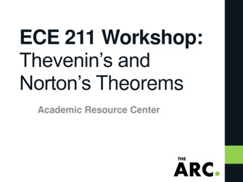
0.2. Thevenin’s and Norton’s Theorems5 j2 2 j2 5 j22 j2 (0.689 j1.724) (1 j1) 1.689 j0.7248Ω5Ω2ΩZAB RTHVABZAB 416.69 0 156 1.689 j0.724 4 2.91 163.25 IAB Figure 899.43ΩAA 6.29 V -Q 16) Find the Thevenin and Nortonequivalent circuit between terminals A-B forthe circuit shown in Figure 93.9.43Ω0.66 A2 5 j3 ABBThevenin’sEquivalentNorton’sEquivalentj5 50 0o V6 BFigure 90Q 15) For the circuit shown in Figure 91Find the Thevenin and Norton equivalentcircuit with respect terminals A-BSolution:5 4 ABSolution:5 VA2 j3 A2 j5 50 0o VIxj2 50 0o VFigure 93-j2 6 50 90o VISCBFigure 94Figure 915 50 0o VI1ABj2 VA 50 VAVA 05j52 j3VA [0.2 j0.2 0.153 j0.23] 102 -j2 I 20.353 j0.43 10100.353 j0.43 18 50.6 50 90 VoVA Figure 922 5 50 0 j25 j2 18.57 68.2 j3 j5 VA A6 BFigure 9550 90 j22 j2 35.35 45 VB VAB VA VB 18.57 68.2 35.35 45 19.69 156 ZAB 5 j5 (2 j3) 65 j5 [(2.5 j2.5) (2 j3)] 6 [(4.5 j5.5)] 6 3.31 j1.4 3.6 23 Dr. Manjunatha P Prof., Dept of ECE, JNN College of Engg Shimoga manjup.jnnce@gmail.com21
0.2. Thevenin’s and Norton’s TheoremsIN18 50.6 VA 2 j32 j3 14.99 5.71 Figure 97 Q 17) Find the Thevenin and Nortonequivalent circuit between terminals A-B forthe circuit shown in Figure 96.5 j5 A 3 50 0o V-j4 ZLI 50 0 25 90 6.933 33.7 8 j1VAB 50 0 6.933 33.7 (5 j5) 9.79 78.65 25 90o V5 B50 0o VA 3 iB-j4 BSolution:j5 A 3 ZABFigure 965 j5 Figure 98-j4 25 90o V(5 j5) (3 j4)8 j1 4.23 j1.15 ΩZAB Dr. Manjunatha P Prof., Dept of ECE, JNN College of Engg Shimoga manjup.jnnce@gmail.com22
0.1. Millman's Theorem 0.1 Millman's Theorem Statement: In a network if it contains a several voltage sources E 1; E 2; E 3::: with an internal impedances Z 1; Z 2; Z 3::: , which are connected in parallel may be replaced by a single voltage source E with internal impedance Z, where E and Z are