Transcription
SPECIAL ISSUE PAPER1181Mass production of bio-inspired structured surfacesS J Abbott1 and P H Gaskell21MacDermid Autotype Ltd, Wantage, Oxon, UK2School of Mechanical Engineering, University of Leeds, Leeds, UKThe manuscript was received on 7 November 2006 and was accepted after revision for publication on 5 March 2007.DOI: 10.1243/09544062JMES540Abstract: Bio-inspired surface structures offer significant commercial potential for the creationof antireflective, self-cleaning and drag reducing surfaces, as well as new types of adhesive systems. The current article explores how the current understanding of the basic science of thebiological structures occurring on the surface of moth eyes, leaves, sharkskin, and the feet of reptiles can be transferred to functional man-made materials, some of the drawbacks of which areshown to offer a long-term challenge to engineers. Explored also is the related topic of how suchsurfaces can be mass-produced, encompassing the important areas of current surface replicationtechniques and the associated acquisition of good master structures.Keywords: biomimetics, motheye, Lotus effect, sharkskin, gecko, microreplication, nanoreplication, embossing, antireflection, self-cleaning, drag reduction, Spiderman1INTRODUCTIONWantage, Oxon OX12 7BZ, UK. email: sabbott@macdermid.comfrom a perspective of manoeuvrability. The latter hasplayed a key role in the general evolutionary processand is central to both hunter and hunted – the cheetah combines both speed and manoeuvrability witha grace that can only be truly appreciated in slowmotion replay! In other areas evolution’s answer isat best equalled, a good example being the invention of Velcro by George de Mestral; patented in 1955,today it forms the basis of a multi-million poundindustry.The success of the mimicry mentioned above isbecause of mankind’s ability to manufacture engineering solutions cost effectively, either en masse(e.g. Velcro) or in small volumes to high levels ofsophistication and precision (e.g. commercial andmilitary aircraft). And as expected, as new manufacturing techniques have come on stream continuedincremental improvements have emerged. Engineering solutions are of course based on the ability ofengineers to design to specified tolerances which satisfy strict quality controls and customer demands;the purpose and result being exact duplication! Fish,plants, insects, etc., on the other hand, are cellbased structures that have evolved over millions ofyears and possess not only their own individualitybut also the ability to self-replicate and in manyinstances self-repair – two highly desirable but equallychallenging features that currently and for the foreseeable future remain firmly beyond the scientificJMES540 IMechE 2007Proc. IMechE Vol. 221 Part C: J. Mechanical Engineering ScienceBiomimetics [1] encapsulates the study and mimicryof nature’s shape, form and function which on manyfronts, through the process of evolution, far excel current human capabilities. Mankind has made someprogress in incorporating nature’s lead to improvetechnology [2]. Indeed, from an engineering standpoint, bio-inspired solutions are not new: flippers,for example, invented by Benjamin Franklin havebeen used as a simple swimming aid since the earlyeighteenth century [3]. However, other engineeringmimicry of nature’s solutions has required far greateringenuity and scientific understanding – for example,despite birds having evolved to fly effortlessly andover long distances, for humans such a feat, whetherfor the purpose of travel or business, only becamea reality with the advent of the jet engine and anassociated deep understanding of the physics underpinning aerodynamics. Another obvious success is theprogress that has occurred in relation to artificial jointand heart valve replacement together with advancesin prosthetics.In the case of aviation, mankind has surpassednature from the standpoint of speed of flight, but not Correspondingauthor: MacDermid Autotype Ltd, Grove Road,Downloaded from pic.sagepub.com at University of Leeds on January 27, 2016
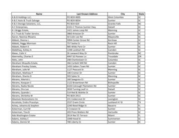
1182S J Abbott and P H Gaskellknowledge horizon. Nevertheless, although nature hasnever ceased to inspire the scientist and engineer alike,the emergence of new and exciting diagnostic equipment such as scanning electron microscopes, atomicforce microscopes, nanoprobes, and high-speed photographic capabilities continues to push at the boundaries in the search for engineering solutions based onnature’s lead. Impetus is also being provided by theadvances being made in the field of nanotechnology.The current article explores the mass production ofengineered surfaces as inspired by: the moth’s eye; thelotus leaf, see also reference [4]; sharkskin; gecko andtree-frog feet. Mass production of bio-inspired products gives rise to two sets of problems. The first is togain a thorough understanding of the physics, chemistry, and engineering of how the biological systemachieves its desirable functionality. The second is tounderstand the strengths and limitations of the production processes and materials which will, usually,be very different from nature’s. In sections 2 to 5 itis shown how the two are intimately intertwined butabove all how the route from bio-inspiration to profitable functional product is hugely multi-disciplinary.It is not too fanciful to suggest that bio-inspiration isleading to the development of new ecosystems in theworld of engineering. Understanding the structures isone thing, implementing them is another; section 6deals with the latter in the context of mass production.Conclusions are drawn in section 7.2The above provides a considerable challenge forany mastering process. Currently, the largest motheye masters are 600 800 mm2 and a practical methodfor creating continuous rollers has still not been realized, though there is active research into alternativetechniques such as growing nanoporous alumina onan aluminium drum, see for example reference [7].Figure 1 shows a motheye structure as replicated intoa hardcoat polymer surface.The antireflection (AR) characteristics of themotheyes are quite attractive. Although practicalimplementation cannot achieve the very low reflectivities of the best sputtered multi-layers, they show verygood angle dependence and colour neutrality. Typically for normal incidence the percentage of reflectedlight at 550 nm (the wavelength where the eye ismost sensitive) is 0.8 per cent. Only above 50 angleof incidence does the reflectivity exceed 1 per cent (A.Gombert, personal communication, 2004). Motheyescan also be implemented in ways that are hard for conventional AR coatings. For example a piece of motheyefilm can be placed into an injection-moulding cavityand made into a thick, three-dimensional componentwith good AR properties [8]. The skills required to bringthis combination together are yet another exampleof how the bio-inspired community is creating newecosystems of industrial interactions.NATURE’S STEALTH TECHNOLOGYThe moth has a problem. It flies in low light levels soneeds large eyes to see where it is going. The laws ofphysics show that 4 per cent of the light hitting the surface of the moth’s eye will be reflected. This reflectedlight is enough to alert the moth’s predators. Whatthe moth needs is stealth technology to reduce thereflectivity. The normal human approach is to create a submicron multi-layer coating using materialssuch as magnesium fluoride that have a low refractiveindex (RI). This is too hard for nature. Instead [5] themoth creates a graded RI on the surface of the eye thatsmoothly goes from RI 1 (air) to RI 1.5 (eye). Physicists with access to advanced optics simulations canshow that a triangular structure is theoretically excellent yet too brittle to survive reality [6]. However, asine-wave structure is almost as good. And that is whatthe moths have come up with. Regular optical structures act as diffraction gratings, which is not what themoth wants. The key trick is to make the structures significantly below the wavelength of light, which thenonly sees them as an average medium of a gradedRI. Thus a typical motheye has a period and depth of200–250 nm.Fig. 1Motheye structure replicated into a hardcoatpolymer surface by MacDermid Autotype. (Imagecourtesy of Fraunhofer ISE)Proc. IMechE Vol. 221 Part C: J. Mechanical Engineering ScienceDownloaded from pic.sagepub.com at University of Leeds on January 27, 2016JMES540 IMechE 2007
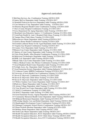
Mass production of bio-inspired structured surfacesOne problem that confronts all AR coatings is thefact that a human finger-print destroys the optical system. For motheyes the problem is that finger greasegets into the structure, and therefore changes thegraded RI. Because these are deep nanostructures itcan be hard to wipe away the grease. One solutionis to reduce the surface energy of the motheye structure. This can be via a subsequent treatment with asilicone or fluoro material, but every extra manufacturing step adds costs. An alternative method is toexploit the manufacturing method itself. A good wayto produce surfaces is via UV cross-linking of systemssuch as acrylates. Acrylates come in a huge variety offorms, from hydrophophilic to hydrophobic. Thus oneapproach is to formulate the UV acrylate system withsufficient hydrophobic content so that it is naturallyhydrophobic after replication. Although this works, itis still not quite good enough. The final part of thesolution is to use a microfibre cloth that can reachinto the depths of the motheye to help remove thefinger grease.Another problem with the motheyes is when theyare used for outdoor applications such as solar cells.Although cross-linked UV acrylate systems are typically seen as being very tough they can easily lose a fewtens of nanometres from the surface when exposed tosunlight. This does not matter when the systems arestandard hardcoat surfaces, but, when you lose tensof nanometres from a motheye the AR performancediminishes rapidly. One approach to solving this problem is to use materials with high silica content such assol-gels [9]; but the large-scale manufacture of suchsystems poses its own set of problems.This digression into the practical issues of these bioinspired films shows up an important but recurringdifference between nature and human engineering.Dirt on a moth’s eye or erosion of the structure issimply fixed – the moth’s eye is a dynamic, growingstructure, refreshing itself all the time. Finding engineering equivalents to such a self-repairing system isgoing to be a tough task.31183designer surfaces [10, 11] and on lab-on-chip devicesfor chemical assay [12]. An up-to-date description ofthe Lotus effect by its discoverer, Barthlott [4], coversthe essentials, and the earlier references therein contain the biological images that inspired his work. Thepurpose of this short section is to provide a reminder ofthe unity of knowledge across diverse fields. See Fig. 2for an example of an artificially created Lotus effectsurface.There are at least three links between motheyes andlotus surfaces.1. They both require high aspect-ratio structureswhich pose similar challenges in origination andreplication.2. The partial solution to the motheye contaminationissue is to make the surface highly hydrophobic.The Lotus effect requires a similar hydrophobization and the same choice exists: carry out a postfunctionalization or build it in to the replicationprocess. The same team that produced successful,practical motheye films [8] was also able to replicatelotus structures that were sufficiently hydrophobicand sufficiently high aspect-ratio (the two requirements) to show the effect straight off the replicationmachine.3. The use of the Lotus effect in the real world islikely to be highly restricted by the ease withwhich the surfaces can become contaminated byoil or grease. It only needs a small reduction inthe hydrophobicity of the surface (for example, amonolayer of a typical oil) or a small reductionin the depth of the structure (again by filling inwith some oil) to destroy the effect entirely, taking it from a superhydrophobe to a Wenzel wettingsurface [13]. Nature solves this problem by continually regrowing the lotus structures; indeed,NATURAL SELF-CLEANINGThe prospect of engineering robust self-cleaning surfaces so that when it rained windows, road signs,indeed all exposed surfaces, were cleaned is atantalizing one! Unsurprisingly nature got there first,with the lotus leaf providing the essential catalystfor work to begin on mimicking the process artificially. Not only was the chemical patterning of theleaf found to be important but also, as with motheyes, the microscale topography present. Similar findings have been exploited elsewhere in relation tounderstanding the motion of droplets on chemicallyand topographically micropatterned heterogeneousJMES540 IMechE 2007Fig. 2Artificial Lotus effect surface created by MacDermid Autotype. (Image courtesy of Creavis)Proc. IMechE Vol. 221 Part C: J. Mechanical Engineering ScienceDownloaded from pic.sagepub.com at University of Leeds on January 27, 2016
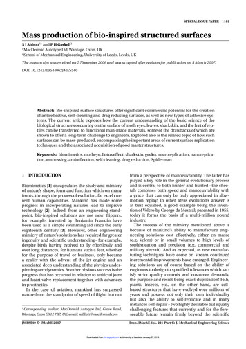
1184S J Abbott and P H GaskellThe pessimistic conclusions in 3. come from reference [14], the content of which is sufficient to dashmany of the more näive hopes of how the Lotuseffect might work. Restricting the problem to twodimensions and treating the structured surface as onecomprised of a series of crenellations (regular spikes) –see Fig. 3 – it is shown that liquid in the form of a dropon a textured (rough) surface can exist in three states.In the hemi-wicking state the liquid in the drop spontaneously flows down the structures (‘wicks’) beyondthe edge of the drop. In the Wenzel state the liquid fillsthe structures below the drop. In the superhydrophobestate the liquid does not enter the structures at all. It isonly in this last state that the drop is free to roll acrossthe surface, taking dirt with it. To the casual observer,the Wenzel state looks very similar to the superhydrophobe state (high contact angle) till the observertilts the substrate to find that the drops do not roll off.The transitions between these states depend on: thestatic contact angle θ [15] determined on a plane surface of the same chemical composition; the fractionφs of the surface which is on top of the structure, normalized by the total surface area such that φs 1; theroughness r which is the ratio of the actual surface areato the apparent (zero texture) surface area, in whichcase for a flat surface r 1. Hemi-wicking wins overWenzel whencos θ 1 φsr φs(1)and superhydrophobe wins over Wenzel whencos θ φs 1r φs(2)they will spontaneously pierce through a layer oflow-hydrophobic contamination. Thus, as with themotheye, the challenge for the long-term future isto create dynamic self-repairing systems.This second equation means that a small reduction inroughness (which can be thought of as a small reduction in depth) or a small decrease in φs or a smalldecrease in θ can transform a self-cleaning surface intoone that does not self-clean at all. This is illustrated inFig. 3, which shows inputs and outputs to the author’scomputer model based on the theory contained in reference [14]. The difference between the two images isa change of the static contact angle from 94 (Wenzelstate) to 102 (super hydrophobic condition).A subsequent paper [16] shows that a very modest hydrostatic pressure (200 Pa) is all it takes toflip from superhydrophobe to Wenzel. This resultmeans that dreams of superhydrophobe surfboardsare impractical. For a review of numerous otheraspects of related effects see reference [17].It is worth noting two more important facts withrelation to the Lotus effect. First, the same effect canbe found on cabbage leaves, but somehow the Cabbage effect does not sound so marketable. Second, itis likely that human ingenuity has come up with a better approach for keeping windows clean. A smooth,Proc. IMechE Vol. 221 Part C: J. Mechanical Engineering ScienceJMES540 IMechE 2007Fig. 3(a) Almost a superhydrophobe, but not goodenough. θsw and θhw are, respectively, the structured wetting and hemi-wicking critical angles.φs is the fraction of the surface on the peaks. (b)A small change in parameters makes the surfacesuperhydrophobicDownloaded from pic.sagepub.com at University of Leeds on January 27, 2016
Mass production of bio-inspired structured surfaceshydrophilic TiO2 surface is the exact opposite of thelotus surface, yet it provides endurable self-cleaningvia two mechanisms. First, the hydrophilic surfacehelps spread water drops into an even, thin film. Second, the TiO2 interacts with UV and oxygen from the airto provide aggressive active oxidizing chemicals thatattack dirt and bio-film to keep the window clean. Thisapproach to cleaning also fits in with a key principleof economy in practical manufacture – the TiO2 has tobe deposited onto a hot, fresh glass surface, but that isexactly what the float glass process provides.4DRAG REDUCTION (WITH SELF-CLEANINGFOR FREE)Sharks, although in general feared, are the refusecollectors of the oceans and spend their whole lifeswimming. Their general shape and musculature hasbeen highly optimized via evolution to make themvery efficient swimmers. Indeed, in terms of shapeand form there is little further that can be done tothe shark to make it even more efficient. Evolution,however, found a way that seems to reduce drag byanother 5–10 per cent. It is not proven that the roughnature of the sharkskin really evolved for this purpose, but as will be shown below it has been proventhat the sharkskin effect can be applied to humanconstructions to give that 5–10 per cent improvement.Similar observations have been made with respectto dolphins [18]. Figure 4 shows a sharkskin surfacecreated using screen printing – the pale coloured, elliptic shaped patterning represent regular protrusionsaligned with the main direction of flow.It seems counter-intuitive that a textured (rough)surface would have less drag than a smooth one, evenin the case of creeping flow over an undulating surface [19]. For the relatively high Reynolds number ofa swimming shark, turbulence is guaranteed. And oneof those well-known, but still surprising facts is thatfor turbulent flow the skin drag (near wall shear stress)is not generally affected by roughness of the surface.Thus a shark’s choice of skin roughness is not a simplefirst-order effect. The way the sharkskin provides dragreduction is complex. For the full story the reader isreferred to reference [20].In simple terms it helps to think of the shark asstationary and the bulk water as moving, with thesharkskin viewed, see Fig. 4, as a series of contiguousprotrusions (riblets) aligned parallel to the local flowdirection of the water. Drag comes from the exchangeof momentum when high-speed water gets convertedinto slow-speed water by the skin and then reinjectedback into the high-speed stream. Because the flow isturbulent it has both parallel and cross-flow (perpendicular) components. Although it is intuitively obviousthat protrusions in the parallel direction will have littleeffect on turbulent flow in that direction, the protrusions influence the flows in the cross direction limitingthe chances for momentum transfer, but, by how muchdoes this reduce the turbulent drag? This seems to bean unanswered question.In a series of papers [21–23] valiant efforts have beenmade to develop a fundamental theory, supportedby a series of careful experiments, to quantify theeffect. By considering the flow over surfaces containing grooves (ribs) running their full length and alignedwith the principal direction of flow, the route to adeeper understanding came with the key observation,from experiments, that the typical size of ribs whichappear to be effective is of the same order of magnitudeas the height of the viscous sublayer of the turbulentmainstream flow. Within the viscous sublayer, thickness hvsl , for the case of turbulent flow over a flatsurface, viscosity dominates, and inertia/convectionis negligible; an approximately linear velocity profilewith constant slope exists. Accordingly, one can write hvsl Fig. 4An experimental screen-printed sharkskinsurface designed by U. Leeds. (Image courtesy ofN. Kapur)JMES540 IMechE 20071185ν2ρτw 1/2(3)where υ is the kinematic viscosity of the fluid, ρ itsdensity and τw the shear stress at the wall. Studying thealterations to the mean longitudinal flow produced bythe presence of longitudinal ribs on a surface [21] gaverise to the crucial idea that the linear velocity profile inthis case appears as if it originates from an equivalentflat surface located at a fixed distance, hL , – termed alongitudinal ‘protrusion height’ – below the tip of theribs. Following a similar argument, a transverse protrusion height, hT , can be defined for the location ofa corresponding virtual flat surface in the cross-flowdirection. Now, if hT hL the viscous cross-flow willProc. IMechE Vol. 221 Part C: J. Mechanical Engineering ScienceDownloaded from pic.sagepub.com at University of Leeds on January 27, 2016
1186S J Abbott and P H Gaskellexperience a higher viscous dissipation and a reduction in the level of near wall turbulence and hencedrag.What seems to be important is the difference in theprotrusion heights, h hL hT , which gives a quantitative measure of whether and by how much ribsimpede the cross-flow more than they do the longitudinal flow – the larger the difference the greater therelative drag reduction in the cross-flow direction. Ofcourse the protrusion heights cannot be greater thanthe height of the ribs, so there is a natural limit to h.Although the calculations of h are precise (becausethey are based on the solution of Stokes equation inthe viscous sublayer), in reference [22] the authorsacknowledge that the correlation between drag reduction and h is not calculable, but it agrees well witha substantial body of experiments [23]. Proving thecorrelation from first principles remains a difficultchallenge for the future.What emerges from the theoretical analysis of hmatches intuition. Very thin, vertical ribs give the bestresult. Broad sinusoidal ribs give an inferior result andsharp triangular ribs are intermediate. These resultsare important because there is a trade-off betweenperformance and practicality (production and robustness). Triangular ribs are particularly well suited tobulk manufacture.Another result which emerges is that a ratio ofabsolute rib height, h, to ‘tip-to-tip’ rib spacing, s, ofh/s 0.5 is the optimal value for thin ribs and thatvalues somewhat higher are optimal for other shapes.However, higher ribs intuitively increase overall dragso the value of 0.5 is a good practical guide. For thereal-world designer the ultimate question is what ‘tipto-tip’ rib spacing is optimal for drag reduction (giventhat the preferred rib height should be half that of therib spacing)?The Reynolds number for the ribs can be defined asskin drag. An 8 per cent drag reduction sounds veryattractive so why are not aircraft, boats (other thansome rare examples of sports boats), and cars regularlycovered with ribs?An example from reference [20] shows the engineering thought process required before anyone would usesharkskin in practice. The skin drag from a typicalaircraft is 50 per cent of the total drag. In reality youcan only cover 70 per cent of an aircraft with ribs. Putthese factors together and the 8 per cent drag reduction becomes a 3 per cent reduction in the total dragon the aircraft. Three per cent is still significant for anairline but so far only one Cathay Pacific Airbus 340has been fitted with a ribbed structure as many othertradeoffs are involved [23].There is another example of unity of knowledge inthis field. Sharks and, as it turned out, the CathayPacific Airbus seem to remain cleaner in their working environment. Clearly this is not because of theLotus effect, but the ribbed surface is making it harderfor dirt and for natures contaminants (from fungae tobarnacles) to stick to the surface!5STICKING TO WALLSwhere uτ (τw /ρ)1/2 . By taking τ τ τw , the difference between the shear stress on a ribbed surface andthat on a flat surface under identical flow conditions,it is that negative values of τ /τw will correspond toa drag reduction and positive values to an increasein drag. Plots [23] of τ /τw against s from experimental data for different rib profiles suggest that dragreduction is optimal for s having a value of approximately 15. It turns out that for typical structures suchas boats and aircraft s is in the 100–200 µm domainwith h therefore in the 50–100 µm domain.With the optimum structure what sort of drag reductions can you obtain? Experiments show that you canapproach a drag reduction of about 10 per cent withsharp rib structures [23]. Mass-producible structuresare more likely to provide an 8 per cent reduction inIt is remarkable to see a gecko walking upside downon a plane sheet of glass and attach its body to a vertical wall using a single toe to support its entire bodyweight, or a tree-frog walking safely along a wet andslippery vertical leaf. There have been many theoriesof how these archetypal examples of animal adhesionwork, with the myth of Spiderman [24] having made itfairly obvious that some sort of sticky adhesive mustbe involved. The reality, however, is both simple andcomplex.The simple part is that if you put any reasonableamount of any two surfaces in intimate contact then inprinciple the van der Waals forces [25] between themare more than sufficient to bear the required load. It issurprising to many people to learn that the apparentlyvery weak van der Waals force (which provide a lowadhesion energy of 50–60 mJ/m2 [26]) is sufficient sothat in principle a human could hang from a smoothglass wall if only the total area of their hands were incontact.A typical flat polymer surface in perfect contact withglass, and with no stored elastic energy can take anadhesive load of 30 000 N/m2 simply from van derWaals forces. Thus a pair of hands of 0.03 m2 total contact area if in perfect contact could support 900 N orabout 90 kg, a typical human weight. No special adhesive bonding is required – just perfect nanometre-scalecontact. And so the problem that geckos and tree-frogshave to solve is how to get perfect contact.It is trivially the case that two planar rigid surfacesonly make intimate contact at three points! HenceProc. IMechE Vol. 221 Part C: J. Mechanical Engineering ScienceJMES540 IMechE 2007s suτν(4)Downloaded from pic.sagepub.com at University of Leeds on January 27, 2016
Mass production of bio-inspired structured surfacesthe actual contact area between any two real-worldsurfaces is usually a tiny fraction of the potential contact area. Intuition suggests that if your hand weremade from a nice rubber then with a bit of pressureyou could get it into intimate contact and becomeSpiderman.Unfortunately, although rubber seems soft and easily deformable to make good contact with a surface,the bulk (or compression) modulus in the z-direction(perpendicular to the surface) for a rubber whichis perfectly constrained in the inplane (surface) x–ydirections is given by E/[3(1 2υ)], where E is theYoung’s (or elastic) modulus and υ is Poisson’s ratio.For rubber υ 0.5 leading to an infinite compression modulus. In reality a piece of rubber is notperfectly restrained in the x–y plane so the compression modulus does not attain this pessimistic value,but nevertheless the general restriction in that planeleads to a very high-effective compression modulus. Ifthere were no restraint in the x–y plane then the rubber is more easily compressed into contact and thecompression modulus is closer to the elastic modulus. To put it another way, if one has a rubber handand presses against a wall, the rubber at the edgescan deform sideways allowing fairly good contact ofthe rubber with the wall, but the rubber in the centreis constrained from sideways movement and cannot effectively be pressed in intimate contact withthe wall.What the gecko does is introduce many more edgesto the rubber so it can expand laterally. It sacrificestotal surface area (by about 50 per cent) to give manytwo-dimensional fibres that can deform to be in perfect contact with the local surface, but there are twolevels of deformation. The first is at the near nanometre level where the modulus effect is so helpful. Thesecond is at a macrolevel of roughness of a wall ora tree. If the fibres are long enough they can flex toaccommodate wide ranges of local roughness. In otherwords you want a compliant fibre.At first it seems as though it is relatively easy to create an artificial gecko foot. Make lots of nanofibresas long, thin (for conformity) and close-packed (formaximum surface area in contact) as possible. Whenthis is tried the result is disappointment, see for example [27]. The long fibres are so easily deformed thatthey bend towards each other and stick in a mat. Theyare useless as a gecko foot.The elegant work contained in reference [27] andof others, shows that there is a maximum fibre lengthto fibre diameter ratio, which depends on the Young’smodulus of the material. The maximum fibre length,l, for a fibre of radius r is given byl r 4/3l01/3JMES540 IMechE 2007(5)1187where l0 is a constant, given byl0 8F03πE (6)where F0 is the adhesion force of the end of the fibrenormal to the surface and is the spacing betweenthe fibres.Good adhesion requires fibres of very low radiusand very small , that is lots of small fibres packedclose together. This intuition is backed up by thework of Arzt et al. [28], which shows that there is alog linear relationship between the number of fibres(setae) per square metre and the mass of the gecko –i.e. bigger adhesion requires more, smaller fibres. Thusformulae (5) and (6) show that to create long fibreswith the necessary high compliance requires very highYoung’s modulus materials. The workhorse material,polydimethylsiloxane (PDMS), (E 0.0006 GPa) can
1184 SJAbbottandPHGaskell Fig.3 (a) Almost a superhydrophobe, but not good enough. θsw and θhw are, respectively, the struc- tured wetting and hemi-wicking critical angles. φs is the fraction of the surface on the peaks. (b) A small change in parameters makes the surface superhydrophobic