Transcription
Dell EMC PowerMax and VMAX All Flash:SRDF/Metro Overview and Best PracticesJanuary 2022H14556.8White PaperAbstractThis document describes the SRDF/Metro enhancement for Dell EMCPowerMax, VMAX3, and VMAX All Flash storage arrays. SRDF/Metrosignificantly changes the traditional behavior of SRDF to better supportcritical applications in high availability environments.Dell Technologies
CopyrightThe information in this publication is provided as is. Dell Inc. makes no representations or warranties of any kind with respectto the information in this publication, and specifically disclaims implied warranties of merchantability or fitness for a particularpurpose.Use, copying, and distribution of any software described in this publication requires an applicable software license.Copyright 2019-2022 Dell Inc. or its subsidiaries. All Rights Reserved. Dell Technologies, Dell, EMC, Dell EMC and othertrademarks are trademarks of Dell Inc. or its subsidiaries. Intel, the Intel logo, the Intel Inside logo and Xeon are trademarksof Intel Corporation in the U.S. and/or other countries. Other trademarks may be trademarks of their respective owners.Published in the USA January 2022 H14556.8.Dell Inc. believes the information in this document is accurate as of its publication date. The information is subject to changewithout notice.2Dell EMC PowerMax and VMAX All Flash: SRDF/Metro Overview and Best Practices
ContentsContentsExecutive summary.4Introduction .6Configuring SRDF/Metro.8SRDF/Metro resiliency .10Host support matrix example .21Features and functionality by service release .23SRDF/Metro device maintenance (add/move operations) .25SRDF/Metro online device expansion (ODE operations) .28SRDF/Metro Smart DR .29Best practices.42Restrictions and dependencies.45Conclusion.47Appendix A: Unisphere setup walkthrough .49Appendix B: Solutions Enabler SYMCLI walkthrough .53Appendix C: Unisphere Createpair –Exempt specific steps .62Appendix D: Unisphere Movepair –Exempt specific steps .69Appendix E: Unisphere Online Device Expansion (ODE) steps.74Appendix F: Unisphere Smart DR walkthrough .78Appendix G: Smart DR and status reference tables .90Appendix H: Technical support and resources.106Dell EMC PowerMax and VMAX All Flash: SRDF/Metro Overview and Best Practices3
Executive summaryExecutive summaryOverviewSymmetrix Remote Data Facility (SRDF) solutions provide disaster recovery and datamobility solutions for Dell EMC PowerMax, VMAX, VMAX3, and VMAX All Flash arrays.SRDF services are provided by the following operating environments: PowerMaxOS for PowerMax 2000 and PowerMax 8000 HYPERMAX OS for VMAX All Flash VMAX 250F, VMAX 250FX, VMAX 450F,VMAX 450 FX, VMAX 850F, and VMAX 850 FX HYPERMAX OS for VMAX3 100K, 200K, and 400K arrays Enginuity for VMAX 10K, 20K, and 40K arraysSRDF replicates data between 2, 3, or 4 arrays located in the same room, on the samecampus, or thousands of kilometers apart. SRDF synchronous (SRDF/S) maintains a real-time copy at arrays located within200 kilometers. Writes from the production host are acknowledged from the localarray when they are written to cache at the remote array. SRDF asynchronous (SRDF/A) maintains a dependent-write consistent copy atarrays located at unlimited distances. Writes from the production host areacknowledged immediately by the local array, thus replication has no impact onhost performance. Data at the remote array is typically only seconds behind theprimary site.HYPERMAX OS 5977.691.684 and Solutions Enabler/Unisphere for VMAX 8.1 introducedsupport for SRDF/Metro for VMAX3 and VMAX All Flash families of storage arrays.SRDF/Metro significantly changes the traditional behavior of SRDF to better support yourcritical applications in high availability environments.With SRDF/Metro, the SRDF secondary device is read/write accessible to the host andtakes on the external identity of the primary device (geometry, device WWN, and so on).By providing this external identity on the secondary device, both the primary andsecondary devices may then appear as a single virtual device across the two SRDFpaired arrays for presentation to a single host or host cluster.With both devices being accessible, the host or hosts (in the case of a cluster) can readand write to both primary and secondary devices with SRDF/Metro ensuring that eachcopy remains current, consistent, and addressing any write conflicts which may occurbetween the paired SRDF devices. A single PowerMax, VMAX3, or VMAX All Flash Arraymay simultaneously support multiple SRDF groups configured for SRDF/Metro operationsand multiple SRDF groups configured for non-SRDF/Metro operations.The following features were introduced with the PowerMaxOS 5978 Q3 2020 ServiceRelease (SR) and Solutions Enabler/Unisphere for PowerMax 9.2:4 SRDF/Metro Smart DR Support for 25 GbE SRDF SRDF/Metro Smart DR provides SRDF/Metro with a single asynchronous targetR22 volume which may be populated from either the R1 or R2 volume of anDell EMC PowerMax and VMAX All Flash: SRDF/Metro Overview and Best Practices
Executive summarySRDF/Metro paired solution. Adding the capability to use a single asynchronoustarget volume simplifies setup, maintenance capabilities, system requirements, andreduces the amount of disk space required for a single target system.This release also added support for the 4 port 25 GbE SLiC and protocol driver for allSRDF replication and host connectivity (RE/SE). This hardware expands PowerMaxsupport for next generation Ethernet-based SAN fabrics, continuing to provide maximumI/O performance and fabric capabilities to the platform.PowerMaxOS 5978 Q2 2019 Service Release and Solutions Enabler/Unisphere forPowerMax 9.1 introduced support for SRDF/Metro Online Device Expansion (ODE) and anew Unisphere interface for add/remove of SRDF/Metro devices based on the existingStorage Group add/remove device workflow. With Unisphere for PowerMax and SolutionsEnabler 9.1 forward, we expanded our ODE support to include devices taking part inSRDF/Metro (Active) sessions; this new functionality is based on modifications to ourexisting Geometry Compatibility Mode (GCM) functionality for host visibility of devices.Unisphere 9.1 also provides new ease-of-use functionality by automating the addition ofdevices to a storage group which then adds corresponding SRDF paired devices forsingle hop, concurrent, and cascaded SRDF configurations.AudienceRevisionsWe value yourfeedbackThese technical notes are intended for IT professionals who need to understand theSRDF/Metro enhancement for the PowerMax, VMAX3, and VMAX All Flash storagearrays. It is specifically targeted at Dell EMC customers and field technical staff who areeither running SRDF/Metro or are considering SRDF/Metro as a viable replication or hostavailability solution.DateDescriptionSeptember 2019Content and template updateSeptember 2020Updates for PowerMaxOS Q3 2020 releaseJanuary 2022Template updateDell Technologies and the authors of this document welcome your feedback on thisdocument. Contact the Dell Technologies team by email.Author: Michael AdamsNote: For links to other documentation for this topic, see the PowerMax and VMAX Info Hub.Dell EMC PowerMax and VMAX All Flash: SRDF/Metro Overview and Best Practices5
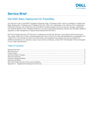
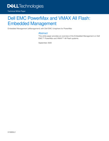
IntroductionIntroductionSRDF/MetrooverviewSRDF synchronous (SRDF/S) mode maintains a real-time copy at arrays generallylocated within 200 kilometers (dependent upon application workload, network latency, andblock size). Writes from the production host are acknowledged from the local array whenthey are written to cache at the remote array creating a real-time mirror of the primarydevices.SRDF disaster recovery solutions, including SRDF synchronous, traditionally use active,remote mirroring and dependent-write logic to create consistent copies of data.Dependent-write consistency ensures transactional consistency when the applications arerestarted at the remote location.An SRDF device is a logical device paired with another logical device that resides in asecond array. The arrays are connected by SRDF links. R1 devices are the member ofthe device pair at the primary (production) site. R1 devices are generally read/writeaccessible to the host. R2 devices are the members of the device pair at the secondary(remote) site. During normal operations, host I/O writes to the R1 device are mirrored overthe SRDF links to the R2 device.Figure 1.Traditional SRDF device pair statesTraditionally, data on R2 devices are not available to the host while the SRDF relationshipis active. In SRDF synchronous mode, an R2 device is typically in read-only mode (writedisabled) that allows a remote host to read from the R2 devices. In a typical open systemshost environment, the production host has read/write access to the R1 device. A hostconnected to the R2 device has read-only access to the R2 device. To access the R2device of a traditional synchronous relationship, a manual failover or swap operation mustbe performed to write enable the R2 site to accept host writes.With the introduction of HYPERMAX OS 5977.691.684 and Solutions Enabler/Unispherefor VMAX 8.1, we have introduced support for SRDF/Metro for VMAX3 and VMAX All6Dell EMC PowerMax and VMAX All Flash: SRDF/Metro Overview and Best Practices
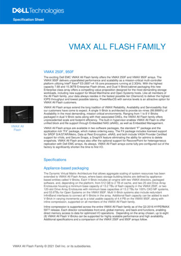
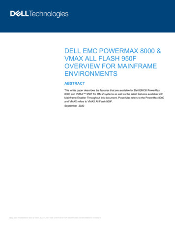
IntroductionFlash families of storage arrays. SRDF/Metro significantly changes the traditionalbehavior of SRDF Synchronous mode with respect to the secondary or remote deviceavailability to better support host applications in high-availability environments. WithSRDF/Metro, the SRDF R2 device is also read/write accessible to the host and takes onthe external identity of the primary R1 device (geometry, device WWN). By providing thisexternal identity on the R2 device, both R1 and R2 devices may then appear as a singlevirtual device across the two SRDF paired arrays for host presentation. With both the R1and R2 devices being accessible, the host or hosts (in the case of a cluster) can read andwrite to both R1 and R2 devices with SRDF/Metro ensuring that each copy remainscurrent, consistent, and addressing any write conflicts which may occur between thepaired SRDF devices.Figure 2.Single and clustered host configurationsThe left example depicts a SRDF/Metro configuration with a stand-alone host which hasvisibility to both VMAX3 or VMAX All Flash arrays (R1 and R2 devices) using hostmultipathing software such as PowerPath, to enable parallel reads and writes to eacharray. This is enabled by federating the personality of the R1 device to ensure that thepaired R2 device appears to the host as a single virtualized device. See Host supportmatrix example and Host multipathing software for additional requirements in this area.The right example depicts a clustered host environment where each cluster node hasdedicated access to an individual VMAX array. In either case, writes to the R1 or R2devices are synchronously copied to its SRDF paired device. Should a conflict occurbetween writes to paired SRDF/Metro devices, the conflicts will be internally resolved toensure a consistent image between paired SRDF devices are maintained to the individualhost or host cluster.SRDF/Metro may be managed through Solutions Enabler SYMCLI or Unisphere forVMAX 8.1 or greater client software and requires a separate SRDF/Metro license to beinstalled on each VMAX3, VMAX All Flash, or PowerMax array to be managed.Dell EMC PowerMax and VMAX All Flash: SRDF/Metro Overview and Best Practices7
Configuring SRDF/MetroKey differencesbetweenSRDF/Metro andstandard SRDFmodesThe key differences between SRDF/Metro and standard synchronous and asynchronousSRDF modes are: All SRDF device pairs that are in the same SRDF group and that are configured forSRDF/Metro must be managed together for all supported operations with thefollowing exceptions: If all the SRDF device pairs are not ready (NR) on the link, the user mayperform a createpair operation to add additional devices to the SRDF group,provided that the new SRDF device pairs are created not ready (NR) on thelink. If all the SRDF device pairs are not ready (NR) on the link, the user mayperform a deletepair operation on all or a subset of the SRDF devices in theSRDF group.An SRDF device pair taking part in an SRDF/Metro configuration may be brought tothe following state: Both sides of the SRDF device pair appear to the host(s) as the same device. Both sides of the SRDF device pair are accessible to the host(s).Configuring SRDF/MetroConfigurationoverviewThe following sections describe the states through which a device pair in an SRDF/Metroconfiguration may transition during the configuration’s life cycle and the external eventsand user actions which trigger these transitions.Figure 3.SRDF/Metro device life cycleThe life cycle of an SRDF/Metro configuration typically begins and ends with an emptySRDF group and a set of non-SRDF devices. Since SRDF/Metro does not currentlysupport concurrent or cascaded SRDF devices unless these devices are part of asupported SRDF/A configuration (see Features and functionality by service release foradditional information), devices that will constitute the SRDF device pairs typically beginas non-SRDF devices. These devices may then return to a non-SRDF state following adeletepair operation, terminating the SRDF/Metro configuration.8Dell EMC PowerMax and VMAX All Flash: SRDF/Metro Overview and Best Practices
Configuring SRDF/MetroCreatepairoperationAn SRDF createpair operation, with an appropriate SRDF/Metro option specified, placesthe new SRDF device pairs into an SRDF/Metro configuration. The user may perform thecreatepair operation to add devices into the SRDF group as long as the new SRDFdevices created are not ready (NR) on the SRDF link with a suspended or partitionedstate.The SRDF device pairs may be made read/write (RW) on the SRDF link as a part of thecreatepair operation by specifying either establish or restore option. The createpairoperation creates the SRDF device pairs and makes them read/write on the SRDF link.Alternately, the user may perform a createpair operation followed by an establish orrestore operation to begin the device synchronization process between newly createddevice pairs. In either case, the resulting SRDF mode of operation will be Active for thesedevices to reflect an SRDF/Metro configuration.Device pairsynchronizationOnce the devices in the SRDF group are made read/write (RW) on the SRDF link, invalidtracks begin synchronizing between the R1 and R2 devices, with the direction ofsynchronization defined by an establish or restore operation. The SRDF mode will remainActive with the device pair state becoming SyncInProg while the device pairs aresynchronizing. During synchronization, the R1 side will remain accessible to the hostwhile the R2 side remains inaccessible to the host.An SRDF device pair will exit the SyncInProg SRDF pair state when either of the followingoccurs:Device pairoperation All invalid tracks have been transferred between the R1 and the R2 for all SRDFdevice pairs in the SRDF group. Any SRDF device pair in the SRDF group becomes not ready (NR) on the SRDFlink. This which will result in all SRDF device pairs of the SRDF/Metro group tobecome NR on the SRDF link. At this point, they simultaneously enter a suspendedor partitioned SRDF link state.Once the initial synchronization has completed, the SRDF device pairs then reflect anActiveActive or ActiveBias pair state and Active SRDF mode. The state of the device pairstate depends upon the resiliency options configured for these devices which will befurther described in SRDF/Metro resiliency.SRDF/Metro devices transition to the ActiveActive or ActiveBias SRDF pair states whenall the following has occurred: The external identity and other relevant SCSI state information have been copiedfrom the R1 side of the SRDF device pairs to the R2 side. The R2 device in each pair has been set to identify itself using the informationcopied from the R1 side when queried by host I/O drivers. The R2 device has been made read/write (RW) accessible to the host(s).At this point, the R2 devices with newly federated personalities from the R1 device maythen be provisioned to a host or host cluster for use by an application. SRDF/Metro R2devices should not be provisioned to a host until they enter an ActiveActive or ActiveBiaspair state.Dell EMC PowerMax and VMAX All Flash: SRDF/Metro Overview and Best Practices9
SRDF/Metro resiliencyGoing forward, host writes to either the R1 or R2 are synchronously copied to its pairedSRDF device. Should a conflict occur between writes to paired SRDF/Metro devices, theconflict will be internally resolved to ensure a consistent image between pairedSRDF/Metro devices is maintained to the individual host or host cluster.FAST integration Performance statistic exchange begins once the SRDF/Metro Active mode andActiveActive or ActiveBias pair state have been achieved. Each side then incorporatesthe FAST statistics from the other side to ensure each side represents the workload as awhole (R1 R2 workload). Users may set the required service level objective (SLO)independently on both source and target SRDF/Metro paired arrays. There are currentlyno restrictions in this area as FAST data movement is transparent from SRDF/Metro.SRDF/Metro resiliencyResiliencyfeaturesSRDF/Metro uses the SRDF link between the two sides of the SRDF device pair toensure consistency of the data. If one or more SRDF device pairs become not ready (NR)on the SRDF link or all link connectivity is lost between VMAX3 or VMAX All Flashsystems (suspended or partitioned states), SRDF/Metro selects one side of the SRDFdevice pair to remain accessible to the hosts, while making the other side of the SRDFdevice pair inaccessible.SRDF/Metro supports two resiliency features to accommodate this behavior, bias andwitness. While both of these features prevent data inconsistencies and split-braincomplications between the two sides of the SRDF device pair. Split-brain complicationsare data or availability inconsistencies originating from the maintenance of two separatedevices (with an overlap in scope) due to a failure caused by these systems notcommunicating or synchronizing their data.The first resiliency feature, bias, is a function of the two VMAX3 or VMAX All Flashsystems taking part in the SRDF/Metro configuration and is a required and integralcomponent of the configuration. The second feature, witness, builds upon the base biasfunctionality by adding an optional SRDF/Metro component which allows a 3rd VMAXbased (PowerMax, VMAX, VMAX3, or VMAX All Flash) or software based (VirtualWitness) node to act as an external arbitrator to ensure host accessibility in cases wherebias alone would restrict access to one side of the SRDF/Metro device pairs. It isimportant to note that these resiliency features are only applicable to SRDF device pairswithin an SRDF/Metro configuration.Each witness may protect the full number of SRDF/Metro groups available on each array.There is a many to many relationship between SRDF/Metro paired arrays and witnessesfor redundancy with each paired array able to be protected by multiple witnesses andeach witness being able to protect multiple arrays. The current support for theserelationships is outlined in the following table:10Dell EMC PowerMax and VMAX All Flash: SRDF/Metro Overview and Best Practices
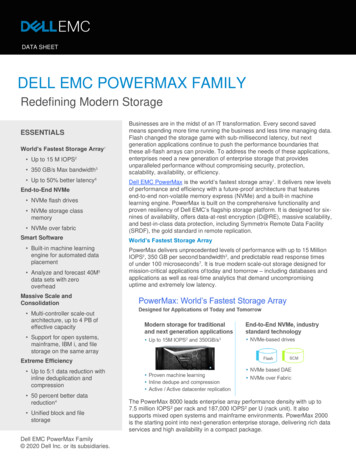
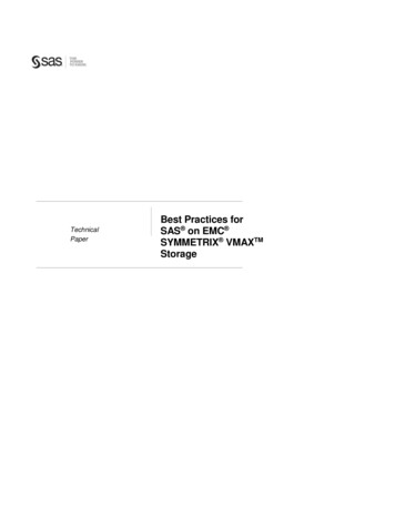
SRDF/Metro resiliencyTable 1.UnderstandingbiasSupport for SRDF/Metro paired arrays and witnessesNumber ofarrayssupportedArray pairssupportedNumber of SRDF/Metro groupsprotected per array pairPhysical Witness3216250 – Number of Physical WitnessRDF GroupsVirtual Witness3216250As described previously, bias is an integral function of the two VMAX3 or VMAX All Flasharrays taking part in a SRDF/Metro configuration. The initial createpair operation placesan SRDF device pair into an SRDF/Metro configuration and pre-configures the bias to theprimary or R1 side of the device pair by default. From then on, the bias side is alwaysrepresented within management interfaces, such as Solutions Enabler SYMCLI orUnisphere for VMAX, as the R1 and the non-bias side as the R2.In the case of a failure causing the device pairs to become not ready (NR) on the link,SRDF/Metro responds by making the non-biased or R2 paired device inaccessible (notready) to the host or host cluster. Bias can optionally be changed by the user once allSRDF device pairs in the SRDF group have reached ActiveActive or ActiveBias SRDFpair states. As noted previously, changing the bias to the R2 side effectively swaps theSRDF personalities of the two sides with the original R2 device pairs now beingrepresented as the R1. Changing bias to the R1 side would be redundant as the R1personality always follows the biased side.Figure 4.Bias point failure examplesIn both examples above, a failure has caused the SRDF/Metro device pairs to become notready (NR) on the link, which resulted in the biased or R1 side remaining accessible(read/write) and the R2 or non-biased side becoming not ready (NR) to the host or hostcluster. The left example represents a single host configuration with the default biasDell EMC PowerMax and VMAX All Flash: SRDF/Metro Overview and Best Practices11
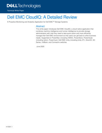
SRDF/Metro resiliencylocation after a user initiated suspend operation, while the right example depicts theresulting post failure configuration after a change in bias was made.As noted previously, there are failure scenarios for which bias alone would not result inthe ideal outcome for continued host accessibility. In the example below, a failureaffecting the R1 or biased side would result in both the R1 and R2 (non-biased) sidesbecoming inaccessible to the host or cluster. For these scenarios, the optional and highlyrecommended redundant witness protection provides the best host accessibility outcome.Figure 5.Understandingthe array-basedwitness12Undesirable bias outcome (with bias side failure)As described previously, the optional witness functionality builds upon the base biasfeature by adding an external arbitrator to ensure host accessibility in cases where biasalone would restrict access. Configuring a hardware witness functionality will require athird VMAX, VMAX3, VMAX All Flash, or PowerMax system with an applicable ePackinstalled and SRDF group connectivity to both the primary and secondary SRDF/Metropaired arrays.Dell EMC PowerMax and VMAX All Flash: SRDF/Metro Overview and Best Practices
SRDF/Metro resiliencyFigure 6.Supported hardware witness configurationsOnce a VMAX witness system has been configured, it supersedes the previouslydescribed bias functionality unless a situation is encountered requiring specific knowledgeof the biased system.The VMAX or VMAX3 code requirements to support witness functionality are: VMAX systems with Enginuity 5876 and SRDF N-1 compatible ePack containing fix82877. VMAX3 system with HYPERMAX OS 5977 Q1 2015 SR and ePack containing fix82878. VMAX3 system with HYPERMAX OS 5977.691.684.To configure a VMAX witness system, SRDF groups created with a new witness optionmust be made visible from the third VMAX, VMAX3, or VMAX All Flash system to both theprimary and secondary VMAX3 systems. This requires SRDF remote adapters (RA’s) tobe configured on the witness system with appropriate network connectivity to both theprimary and secondary arrays. Redundant links to the witness system are alsorecommended as a best practice in a production environment to address possible failuresin connectivity.Once this third system is visible to each of the SRDF/Metro paired VMAX3 or VMAX AllFlash systems and the SRDF/Metro groups suspended and reestablished, theconfiguration enters a “Witness Protected” state. For this reason, it is also a best practicefor the witness SRDF groups to be configured prior to establishing the SRDF/Metro devicepairs and synchronizing devices.Multiple VMAX witness systems may be configured in this manner for redundancypurposes. Should either connectivity or the primary witness system fail and no otheralternative witness systems may be identified, SRDF/Metro resiliency defaults back to theDell EMC PowerMax and VMAX All Flash: SRDF/Metro Overview and Best Practices13
SRDF/Metro resiliencybias functionality. See Use bias resiliency option and failure scenarios below for use in theevent of scheduled maintenance of the witness system. Use of this option prevents dialhome events and escalations normally associated with an outage of SRDF/Metro in awitness configuration.Note: Note that the SRDF personality of devices may also change as a result of a witness action(PowerMax, VMAX, or vWitness based) to better reflect the current availability of the resultingdevices to the host. For example, should the witness determine that the current R2 devicesremain host accessible and the R1 devices inaccessible, the current R2 devices will change to R1as a result. Depending on access/availability, the previous R1 device will also change to R2’s asin the case of a bias change.Figure 7.Desirable witness outcome (bias side failure)Using the undesirable bias outcome example described previously, a failure of the biasedR1 side with a witness configured would now result in continued host accessibility of thenon-biased R2 side:The SRDF/Metro witness functionality covers a number of single and multiple failure andresponse scenarios.Note: To determine the actions necessary to properly recover SRDF/Metro from a specific failurescenario, please refer to the SRDF/Metro Recovery Knowledge Base (KB) article KB516522(https://support.emc.com/kb/516522), engage Dell EMC support directly, or escalate to your localaccount or support team as the urgency of the situation dictates.Depicted below are detailed single and multiple failure scenarios and the resultingresponses which are covered by SRDF/Metro witness functionality:14Dell EMC PowerMax and VMAX All Flash: SRDF/Metro Overview and Best Practices
SRDF/Metro resiliencyFigure 8.Single failure witness scenariosDell EMC PowerMax and VMAX All Flash: SRDF/Metro Overview and Best Practices15
SRDF/Metro resiliencyFigure 9.Understandingthe VirtualWitness(vWitness)16Multiple failure witness scenariosWhile the advantage of the previously described VMAX based witness solutions continuesto be the high availability of the VMAX product and which is especially beneficial for thecustomers with existing VMAX systems, a disadvantage of this approach is therequirement for additional VMAX hardware for new customers. The SRDF/Metro VirtualWitness (vWitness) solution, in contrast, provides alternative witness functionality withoutrequiring additional VMAX hardware. Operationally, virtual and physical witnesses aretreated the same by HYPERMAX OS and SRDF/Metro. They each offer equivalentfunctionality and may be employed independently, simultaneously, and securely. If botharray-based witness and vWitness are available, SRDF/Metro will prefer the array-basedDell EMC PowerMax and VMAX All Flash: SRDF/Metro Overview and Best Practices
SRDF/Metro resiliencywitness. It is important to note that a vWitness will only be used if an array-based witnessis not available.The benefits of a vWitness configuration are the following: Does not require additional VMAX hardware. Offers functional equivalence to existing array-based witness solutions. Connections are secured using TLS/SSL based IP connectivity. Virtual and array-based witness solutions may be used simultaneously.In addition to the vWitness summary information presented below, a separateconfiguration document is available on support.emc.com entitled VMAX vWitnessConfiguration Guide and is focused exclusively on vWitness installation, configuration,and management. See this document for additional vWitness information.The SRDF/Metro vWitness is available for VMAX storage arrays running HYPERMAX OS5977 Q3 2016 Service Release and Solutions Enabler/Unisphere for VMAX 8.3 or later.The vWitness will be packaged as a VMware virtual appliance (vApp) for installationdirectly into the customer environment. This package will support Unisphere for VMAX orSolutions Enabler vApp kits with the Solutions Enabler kit being preferred due to its lowerhardware requirements for those not requiring the f
HYPERMAX OS for VMAX All Flash VMAX 250F, VMAX 250FX, VMAX 450F, VMAX 450 FX, VMAX 850F, and VMAX 850 FX HYPERMAX OS for VMAX3 100K, 200K, and 400K arrays Enginuity for VMAX 10K, 20K, and 40K arrays SRDF replicates data between 2, 3, or 4 arrays located in the same room, on the same campus, or thousands of kilometers apart.