Transcription
US Army Corpsof EngineersAfghanistan Engineer DistrictAED Design Requirements:Sanitary Sewer & Septic SystemVarious Locations,AfghanistanJune 2010Version 1.6
AED Design RequirementsSanitary Sewer & Septic SystemsTABLE OF CONTENTSAED DESIGN REQUIREMENTSFORSANITARY SEWERS & SEPTIC TANKSVARIOUS LOCATIONS,AFGHANISTANSectionPage1. General52. Field Investigations5a) Site Surveyb) Percolation testing553. Sanitary Sewer Systema)b)c)d)e)f)g)h)i)j)k)8Sanitary Sewer System LayoutProtection of Water SuppliesQuantity of WastewaterGravity SewersPipe, Fittings and ConnectionsManholesBuilding Connections and Service LinesCleanoutsGrease InterceptorsOil Water SeparatorsField Tests and Inspections4. Septic c TankAbsorption FieldPressure Dosing of Leach FieldsLeaching ChambersSeepage Pits1313151729305. Design Submittal Information326. As-Builts332
AED Design RequirementsSanitary Sewer & Septic SystemsTablesPageTable 1. Minimum Slopes for Sewers11Table 2. Soil Treatment Areas in Square Meters17Table A-1. Orifice Diameter24Table A-2. Friction loss in plastic pipe26Table A-3. Friction losses through plastic fittings26Table A-4. Void Volume for various diameter pipes27Table 7-6. Sidewall Areas of Circular Seepage Pits32PageFiguresFigure 1. Percolation Testing7Figure 2. Schematic Pipe Definitions11Figure 3. Pressure Distribution System19Figure 4. Typical Pressurized Flow Distribution Device20Figure 5. Typical Flow Distribution Valve20Figure 6. Orifice Spacing23Figure 7. Example of a Dosing Tank28Figure 8. Example of Leaching Chamber Trench Installation29Figure 9. Example of Leaching Chamber Trench Installation30Figure 10. Seepage Pit Cross Section31PageExamplesExample 1: Calculating Percolation Rates6Example 2: Size of a Septic Tank143
AED Design RequirementsSanitary Sewer & Septic SystemsExample 3: Size of an Absorption Field16Example 4: Size a Pressure Distribution Network22Example 5: Size of a Seepage Pit32AppendixAppendix A - Example Gravity Sewer CalculationAppendix B – Drawing DetailsSeptic Tank DetailsAbsorption Bed and Trench DetailsDosing system LayoutLeaching Chambers Option 1A and 1B (Traffic Loading)Leaching Chambers Option 24
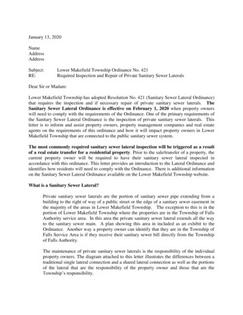
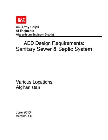
AED Design RequirementsSanitary Sewer & Septic Systems1. GeneralThe purpose of this document is to provide requirements to Contractors for any project requiringsanitary sewer and septic system design and construction. Effluent disposal is typically providedby leach fields, absorption beds, leaching chambers, or seepage pits. Septic systems areconsidered appropriate where the native soil conditions natural percolation properties providebiological treatment of the wastewater after receiving primary treatment in a septic tank. Becauseof the difficulty of distributing effluent uniformly over larger sites and the impacts of its applicationon the underlying groundwater, septic tanks are typically limited to projects where the totaleffective design population is less than 650 personnel. Depending upon the water usage rateadopted for the project, this is typically an average daily flow rate of approximately 121,000 to148,000 liter per day (32,000 to 39,000 gallons per day) assuming 80% wastewater generatedfrom water usage and a capacity factor of 1.5 for treatment.Holding tanks may be authorized as an alternative to effluent disposal means in the projectcontract technical requirements. Because the costs of hauling wastewater and the uncertainty inits sanitary disposal once offsite are greater, holding tanks should be limited to smallerinstallations when no other alternatives are possible. The break even cost for package WWTPconstruction and annual operating cost versus the annual septage hauling cost for holding tanksindicates that installations having design populations in excess of approximately 650 personnelwould be better served by a package WWTP provided sufficient land and effluent disposal meansare available.2. Field Investigationsa) Site Survey. The first step, when designing the sewer system, is determining existing siteconditions. The existing site conditions shall be determined by conducting field investigations atthe proposed site. As part of the field investigations, the Contractor shall conduct a topographicsurvey to determine existing site characteristics. Knowing this information will help determinewhether a gravity system or a pressure system will be used and where to locate the septicsystem. In addition, the Contractor shall conduct a utility survey to determine the locations of anynearby water lines, wells, sanitary sewers, storm sewers and electrical lines. By knowing thelocation of the existing utilities, the Contractor can properly lay out the system.b) Percolation Testing. The second step, once the site has been surveyed, is to performpercolation tests. While performing the tests, observe the soil characteristics and watch forgroundwater within the test area. The site may be considered unsuitable if the following occurs:the soil appears to have too much sand or clay; groundwater is encountered; and/or thepercolation rates are too slow. If the site is determined to be unsuitable, the septic system willneed to be relocated. If another location cannot be found, then an alternative treatment systemwill need to be designed. If this happens, contact the COR.Percolation testing may be carried out with a shovel, posthole digger, solid auger or otherappropriate digging instruments. Percolation tests shall be accomplished uniformly throughoutthe area where the absorption field is to be located. Percolation tests determine the acceptabilityof the site and serve as the basis of design for the liquid absorption. Percolation tests will bemade as follows (see Figure 1).(1) Three or more tests will be made in separate test holes uniformly spaced over theproposed absorption field site. The average of the six tests shall be determined and will beused as the final result. The location of each test shall be clearly and accurately shownon the site plan submitted to AED.(2) Dig or bore a hole to the required depth of the proposed trenches or bed, with dimensionsnecessary to enable visual inspection during percolation testing.5
AED Design RequirementsSanitary Sewer & Septic Systems(3) Carefully scratch the bottom and sides of the excavation with a knife blade or sharppointed instrument to remove any smeared soil surfaces and to provide a natural soilinterface into which water may percolate. Add 50 mm of gravel (of the same size that is to beused in the absorption field) to the bottom of the hole. In some types of soils the sidewalls ofthe test holes tend to cave in or slough off and settle to the bottom of the hole. It is mostlikely to occur when the soil is dry or when overnight soaking is required. The caving can beprevented and more accurate results obtained by placing in the test hole a wire cylindersurrounded by a minimum 25 mm layer of gravel (of the same size that is to be used in theabsorption field.)(4) Carefully fill the hole with clear water to a minimum depth of 300 mm above the gravel orsand. Keep water in the hole at least 4 hours and preferably overnight. In most soils it will benecessary to augment the water as time progresses. Determine the percolation rate 12 to 24hours after water was first added to the hole. In sandy soils containing little clay, this prefilling procedure is not essential and the test may be made after water from one filling of thehole has completely seeped away.(5) The percolation-rate measurement is determined by one of the following methods:(a) If water remains in the test hole overnight, adjust the water depth to approximately 150mm above the gravel. From a reference batter board, as shown in Figure 1, measure thedrop in water level over a 30-minute period. This drop is used to calculate the percolationrate.(b) If no water remains in the hole the next day, add clean water to bring the depth toapproximately 150 mm over the gravel. From the batter board, measure the drop in waterlevel at 30-minute intervals for 4 hours, refilling to 150 mm over the gravel as necessary. Thedrop in water level that occurs during the final 30-minute period is used to calculate thepercolation rate.(c) In sandy soils (or other soils in which the first 150 mm of water seeps away in less than 30minutes after the overnight period), the time interval between measurements will be taken as10 minutes and the test run for 1 hour. The drop in water level that occurs during the final 10minutes is used to calculate the percolation rate.The percolation rate is the number of minutes it takes to drop 25 mm. On page 10, Table 2 listspercolation rates and the corresponding absorption field sizing factor (liters/m2/day). The sizingfactors are used, in conjunction with average daily demand (ADD), to determine the size of theabsorption field. The following is an example of how to calculate the percolation rate:Example 1: Calculating Percolation Rates - In 30 minutes, the measured drop in the waterlevel is 15 mm.Minutes/25 mm Time/(drop/25 mm) 30 minutes/(15 mm/25 mm) 50 Minutes/25 mmwhere,Minutes/25 mm Minutes for water to drop 25 mm.6
AED Design RequirementsSanitary Sewer & Septic SystemsFigure 1. Percolation Testing.7
AED Design RequirementsSanitary Sewer & Septic Systems3. Sanitary Sewer Systema) Sanitary Sewer System Layout. The development of the sewer system (a.k.a. - sanitarypipe collection network) must await the determination of the proposed compound layout, includingdetermining locations for: buildings (including final first floor elevations and utility connections),perimeter wall, and roads, water well, septic system, power supply system, storm drainage andother features. Once the locations for these structures are determined, the Contractor can begindesigning the layout of the sanitary sewers in conjunction with the water supply system. Thefollowing general criteria will be used where possible to provide a layout which is practical andeconomical and meets hydraulic requirements:(1) Follow slopes of natural topography for gravity sewers.(2) Check subsurface investigations for groundwater levels and types of subsoilencountered. If possible, avoid areas of high groundwater and the placement of sewersbelow the groundwater table.(3) Avoid routing sewers through areas which require extensive restoration or undergrounddemolition.(4) Depending upon the topography and building location, the most practical location ofsanitary sewer lines is along one side of the street. In other cases they may be locatedbehind buildings midway between streets. The intent is to provide future access to the linesfor maintenance without impacting vehicular traffic.(5) Avoid placing manholes in low-lying areas where they could be submerged by surfacewater or subject to surface water inflow. In addition, all manholes shall be constructed 50mm higher than the finished grade, with the ground sloped away from each manhole fordrainage.(6) Sewer lines shall have a minimum of 800 mm of cover for frost protection.(7) Locate manholes at change in direction, pipe size or slope of gravity sewers.(8) Sewer sections between manholes shall be straight. The use of a curved alignment shallnot be permitted.(9) If required by the design, locate manholes at intersections of streets where possible.This will minimize vehicular traffic disruptions if maintenance is required.(10)Sewer lines less than 1.25 meters deep under road crossings shall have a reinforcedconcrete cover of at least 150 mm thickness around the pipe or shall utilize a steel or ductileiron carrier pipe. It is recommended to continue the reinforced concrete cover or carrier pipea minimum of one (1) meter beyond the designated roadway.(11)Sewer lines entering a manhole shall not be less than 90 degrees to the orientation of thesewer line leaving the manhole.(12)Verify that final routing selected is the most cost effective alternative that meets servicerequirements.b) Protection of water supplies. Sanitary sewer design shall meet the following criteria:8
AED Design RequirementsSanitary Sewer & Septic Systems(1) Sewers shall be located no closer than 15 meters measured horizontally to water wells orearthen reservoirs that are used for potable water supplies.(2) Sewers shall be located no closer than 3 meters measured horizontally to potable waterlines; where the bottom of the water line will be at least 300 mm above the top of the sewerline, the horizontal space shall be at a minimum of 1.83 meters.(3) Sewer lines crossing above potable water lines shall be constructed of suitable pressurepipe or fully encased in concrete for a distance of 3 meters measured horizontally on eachside of the crossing. If concrete encasement is used, the sewer line shall be encased with aminimum of 150 mm of cover all the way around the pipe. Pressure pipe will be as requiredfor force mains in TM 5-814-2/AFM 88-11, Chapter 2, and shall have no joint closer than 1meter horizontally to the crossing, unless it is fully encased in concrete.c) Quantity of Wastewater. The design of the wastewater system shall be based on twofactors: the average daily flow and the peak diurnal flow (PDF).(1) Average Daily Flow (ADF). The Contractor shall verify the average daily flow consideringboth resident (full occupancy) and non-resident (8hr per day) population. The average daily flowwill represent the total waste volume generated over a 24-hour period, and is defined as 80% ofthe product of the total population of the facility (c), the per capita water usage rate per day(ADD) , and the applicable capacity factor (CF) (0.8* c*ADD*CF). The capacity factor forinstallations with populations less than 5,000 residents is 1.5. Capacity factors for largerinstallations shall be determined using Chapter 4 Basic Design Considerations, UFC 3-240-09FADomestic Wastewater Treatment, Table 4-1. For example, the average daily flow at a compoundwith a population of 500 personnel, would be calculated by multiplying the population (500) by thewater usage rate (190 lpcd) by the capacity factor (1.5) by 80% resulting in a flow of 114,000liters/day (30,160 gallons per day).(2) Peak diurnal rates (PDF) of flow occur on a daily basis and must be considered. Thesewer shall be designed with adequate capacity to handle these peak diurnal flow rates. Thepeak diurnal flow rate is computed by the following equation:PDF Q C2Q0.167Where PDF Peak diurnal flowrateQ Average daily flow in gallons per day (including the capacity factor)C 38.2 for gallons per daySo for the same compound with a population of 500 personnel, the peak diurnal flow rate wouldbe the 114,000 liters/day (calculated above multiplied by 38.2 divided by 2 times (30,160)0.167which equals 389,027.3 liters per day.d) Gravity Sewers. The method for designing the sanitary sewers shall be determinedaccording to the installation population.(1) For installations with populations less than 450 personnel, all sewer pipe slopes shall bea minimum of 1.0%, regardless of pipe size. If this slope and surface topography forcethe laterals in the absorption field more than 1500mm below the surface of the ground, alift station is necessary. When this occurs, the designer should contact AED immediatelyto discuss options. Gravity flows are always desirable, but lift stations may be necessaryin certain circumstances.(A) Minimum Pipe Diameter. The minimum pipe diameter used in the sewer system forthis size installation (after the building plumbing connection) shall be 150mm. This9
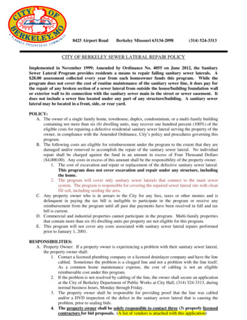
AED Design RequirementsSanitary Sewer & Septic Systemsdiameter pipe may be used throughout the installation. This shall be the minimumsize. Larger pipe diameters may be used, but should be used only if flows require alarger diameter.(2) For installations with populations greater than or equal to 450 personnel the sanitarysewer shall be designed to meet the following conditions. If, based on the followingconditions, it is determined that a lift station is necessary to meet the flow and pipe sizerequirements than the designer should contact AED immediately.(A) Peak Diurnal Flow (PDF). Piping shall be designed to provide a minimum velocity of0.6 meters per second (mps) or (2.0 feet per second (fps) and shall NOT flow at greater than 80%full or at a velocity greater than 3.0 mps (10 fps). It is required that all the pipes are designed toachieve a scouring velocity of 0.6 mps at the PDF.(B) Average Daily Flow (ADF). When possible, piping shall be designed to provide aminimum scouring velocity of 0.6 mps ( 2.0 fps) at the ADF, and shall NOT flow at greater than80% full or at a velocity greater than 3.0 mps (10 fps) in every segment of the sewer system. It ispreferred that the scouring velocity be achieved by the ADF however it is not a requirement(C) Flow Allocation. Flows in laterals, mains and trunk lines shall be based on allocatingthe proportion of the average daily and peak diurnal flow to each building or facility on the basis ofthe drain fixture unit flow developed for the plumbing design. [For example, consider a lateralreceiving flow first from building A, then from building B and then from building C prior toemptying into a main. These buildings have drain fixture units of 10, 25, and 5, respectively. Theentire facility has a total of 6 building and a total of 80 drain fixture units. The flows used todesign the lateral receiving flow from building A would be 10/80 times the ADF and the PDF. Theflows used to design the lateral after receiving flow from buildings A and B would be (10 25)/80times the ADF and the PDF. Finally, the flows used to design the lateral after receiving flowsfrom buildings A, B, and C would be (10 25 5)/80 times the ADF and the PDF.](D) Minimum Pipe Slopes. Table 1 defines the minimum pipe slopes allowed in the sewersystem. These shall be the minimum provided, regardless of the calculated flow velocities toprevent settlement of solids suspended in the wastewater. Table 1 does not apply to buildingconnections.(E) Building connection. Sewer lines from buildings will be designed to provide aminimum velocity of 0.6 meters per second or 2.0 feet per second at the drain fixture unit flow forthat building. The building connection is the pipe from the building to a manhole or pipe that hasmore than one pipe entering it, see Figure 2. The minimum slope of building connection shall be1% regardless the size of the installation.(F) Minimum Pipe Diameter. The minimum pipe diameter used in the sewer system (afterthe building plumbing connection) shall be 150mm. These sizes shall be provided regardless offlows being received. Larger pipe diameters shall be provided in the sewer system based on flowand velocity requirements.Unless otherwise indicated (see Paragraph 3 (g) Building Connections and Service Lines below),gravity sewer pipe shall be installed in straight and true runs in between manholes with constantslope and direction. Pipe slopes shall be sufficient to provide the required minimum velocitiesand depths of cover on the pipe. Table 1 below provides the minimum allowable slopes forvarious diameter pipes. Table 1 does not apply to installations with populations less than 450persons. The minimum slope for 150mm piping at these installations is to be 1%.10
AED Design RequirementsSanitary Sewer & Septic SystemsTable 1. Minimum Slopes for Sewers (PopulationsGreater than 450).Minimum Slope in Metersper 100 MetersSewer Size100 mm1.00150 mm0.62200 mm0.40250 mm0.28300 mm0.22350 mm0.17375 mm0.15400 mm0.14450 mm0.12525 mm0.10600 mm0.08This table does not state that pipes are designed at this slope regardless of flow depth andvelocity. Other criteria listed above shall be used to determine the slopes necessary to meet theconditions previously listed above. The word “minimum” is defined as “the least quantity oramount possible, assignable, allowable, or the like”. Greater slopes shall be used as needed toachieve the design requirements previously listed.S E W E R M A INMH 4B U IL D IN GC O N N EC TIO NLA TR IN EMH 3B U IL D IN G C O N N EC TIO NS EN IO RBA RRA CKSG R EA SE TR APL ATER AL / M AIND IN IN GF A C ILITY(DFA C)A D M INB UILD IN GMH 1C L EAN O U T (TYP IC AL EV ER YB U IL D IN G C O N N EC TIO NB U IL D IN G C O N N EC TIO NMH2L ATER AL / M A INB U IL D IN G C O N N EC TIO NFigure 2. Schematic Pipe Definitions11
AED Design RequirementsSanitary Sewer & Septic Systemse) Pipe, Fittings and Connections. Pipe, fittings and connections shall conform to therespective specifications and other requirements as listed in Contract Section 01015 and all of itsreferenced codes.f) Manholes.(1) The distance between manholes must not exceed 120 meters in sewers of less than 450mm in diameter. For sewers 450 mm in diameter and larger, a spacing of up to 180 meters isallowed provided the velocity is sufficient to prevent settlement of solids.(2) For pipe connections, the crown of the outlet pipe from a manhole will be on line with orbelow the crown of the inlet pipe. Where conditions are such as to produce unusualturbulence in the manhole, it may be necessary to provide an invert drop to allow for entryhead, or increased velocity head, or both. Where the invert of the inlet pipe would be morethan 450 millimeters above the manhole floor, a drop connection will be provided.(3) Manhole frames and covers must be sufficient to withstand impact from wheel loadswhere subject to vehicular traffic. Covers with nominal sides measuring 762 mm or largershall be installed where personnel entry may occur. Cover frames and/or heavy duty hingesshall prevent covers from dropping into the manholes, or circular covers shall be provided.(4) The following construction practices will be required: 1) Smooth flow channels will beformed in the manhole bottom. Laying half tile through the manhole, or full pipe with the topof the pipe being broken out later, are acceptable alternatives; 2) for manholes over 1 meterin depth, one vertical wall with a fixed side-rail ladder will be provided; 3) drop connectionswill be designed as an integral part of the manhole wall and base; 4) in areas subject to highgroundwater tables, manholes will be constructed of materials resistant to groundwaterinfiltration.(5) The primary construction materials to be used for manhole structures are precastconcrete rings and cast-in-place, reinforced concrete. Cast-in-place construction permitsgreater flexibility in the configuration of elements, and by varying reinforcing the strength ofsimilar sized structures can be adjusted to meet requirements. In general, materials usedshould be compatible with local construction resources, labor experience, and should be costcompetitive. Concrete shall have a 21 MPa minimum compressive strength at 28 days.g) Building Connections and Service Lines. Building connections will be planned to eliminateas many bends as practical and provide convenience in rodding. Bends greater than 45 degreesmade with one fitting shall be avoided and shall be made with combinations of elbows such as45-45 or 30-60 degrees. Provide a cleanout at every combination of elbows.h) Cleanouts. Cleanouts provide a means for inserting cleaning rods into the undergroundpiping system. Install a cleanout within 2 meters of a building on all sewer building connections.A manhole may be used in lieu of a cleanout. An acceptable cleanout will consist of an upturnedpipe terminating at, or slightly above, final grade with a plug or cap. Preferably the cleanout pipewill be of the same diameter as the sewer pipe, but never smaller than 150 mm.i) Grease Interceptors. Grease interceptors are used to remove grease from wastewater toprevent it from entering the sanitary sewer and septic systems. All Dining Facilities (DFACs) shalldrain DFAC cooking and sink and floor drain waste to a grease interceptor prior to the sanitarysewer system. The grease interceptor shall connect to the sanitary sewer system. Sanitarywastes from the DFAC shall flow in a separate pipe to the sanitary sewer system and shall notflow into the grease interceptor.12
AED Design RequirementsSanitary Sewer & Septic SystemsThe grease interceptor shall either be a gravity type or hydro-mechanical type. If the designerselects a gravity type, the grease interceptor shall be of reinforced cast-in-place concrete,reinforced precast concrete or equivalent capacity commercially available steel, with removablethree-section, 9.5 mm checker-plate cover, and shall be installed outside the building. Concreteshall have 21MPa minimum compressive strength at 28 days. Steel grease interceptors shall beinstalled in a concrete pit and shall be epoxy-coated to resist corrosion as recommended by themanufacturer. For sizing of the grease interceptor, follow the guidance provided in the AEDDesign Guide which is based on the EPA document 625/1-80-012 Onsite Wastewater Treatmentand Disposal Systems.If the designer selects a hydro-mechanical type, the grease interceptor shall be sized and testedin accordance with Standard PDI- G101, Testing and Rating Procedure for Type I HydroMechanical Grease interceptors with Appendix of Installation and Maintenance.Drainage to grease interceptors shall be separate and distinct from other sanitary sewer lines.Wastes that do not required treatment or separation shall not be discharged into any interceptoror separator, per ICC IPC 2007 Section 1003.2 Approval.j) Oil Water Separators. Design and install oil water separators per the AED Design Guide whichis based on the ICC IPC 2007 Section 1003.4.2 Oil Separator Design.k) Field Tests and Inspections. Prior to burying the sewer lines, field inspections and testingshall be done to ensure the lines were properly installed and free of leaks. When conductingtests and inspections the following steps shall be conducted:(1) Check each straight run of pipeline for gross deficiencies by holding a light in a manhole;it shall show practically a full circle of light through the pipeline when viewed from theadjoining end of the line. When pressure piping is used in a non-pressure line for nonpressure use, test this piping as specified for non-pressure pipe.(2) Test lines for leakage by either infiltration tests or exfiltration tests.(3) Deflection testing will not be required however; field quality control shall ensure that allpiping is installed in accordance with deflection requirements established by themanufacturer.4. Septic Systema) General. When determining an appropriate septic tank location, the Contractor shall provideprotection for the septic system by ensuring that vehicles, material storage and future expansionshall be kept away from the area. Signage or other prevention methods (i.e., pipe bollards) shallbe used to provide this protection. The finished grade for the site shall ensure that storm waterrunoff shall drain away from the site to prevent ponding, inflow and infiltration. Once anappropriate site is located, the Contractor shall conduct soil investigations for the site todetermine ground water levels, soil conditions and the percolation rate.b) Septic Tank. Septic tanks are buried, watertight receptacles designed and constructed toreceive and partially treat wastewater. The tank separates solids from the liquid, provides limiteddigestion of organic matter, stores solids, and allows the clarified liquid to discharge for furthertreatment and disposal. Settleable solids and partially decomposed sludge accumulate at thebottom of the tank, while scum rises to the top of the tank’s liquid level. The partially clarifiedliquid is allowed to flow through an outlet opening position below the floating scum layer. Theclarified liquid will be disposed of to the absorption field for further treatment and disposal.13
AED Design RequirementsSanitary Sewer & Septic SystemsFactors to be considered in the design of a septic tank include tank geometry, hydraulic loading,inlet and outlet configurations, number of compartments and temperature. If a septic tank ishydraulically overloaded, retention time may become too short and solids may not settle properly.For Afghanistan, a baffled multi-compartment or dual chamber design shall be utilized. Refer toAttachment A for further details. The septic tank shall be designed with a length-to-width ratio of2:1 to 3:1 and the liquid depth should be between 1.2 meters and 1.8 meters. This depth isdetermined by the outlet pipe invert elevation. If not specified in the contract, the septic tank shallbe sized based on the ADF, an additional 100% for sludge storage capacity and peak flows(0.8*c*ADD*CF*2). The tank shall be constructed of reinforced, cast-in-place concrete, with aminimum compressive strength of 21MPa at 28 days. Wastewater influent and effluent shallenter and exit on the short sides of the tank, which will allow the wastewater longer detention andsettling time. The baffled tank shall have two compartments, with the first compartment (influententry point) having 2/3 thirds the volume capacity of the tank. The tank shall have a minimumearth backfill cover of 300 mm. Access shall be provided at the entry (influent) and exit (effluent)points of the tank by installing reinforced concrete risers, with steel access hatches, that will rise50 mm above the finished grade. The following is an example of how to determine the volumeand dimensions of the septic tank:Example 2: Size a Septic Tank - Size a septic tank for a design population of 120individuals.-Assume that tank volume and dimensions are not specified in the contract documents.V ADD*0.8*c*2*CF 190 (liters/capita/day)*0.8*120(capita)*2(sludge retention)*1.5(capacity factor) 54,720 liters (54.72 m3)Where,ADD Average Daily Demand (Water Flow) per Person (liters/capita/day)0.8 conversion of water use to sewage flowc design population (capita)2 represents an additional 100% storage for sludge and peak surgesCF Capacity Factor from UFC 3-240-09FA Domestic Waste
Sanitary Sewer & Septic Systems 5 1. General The purpose of this document is to provide requirements to Contractors for any project requiring sanitary sewer and septic system design and construction. Effluent disposal is typically provided by leach fields, absorption beds, leaching chambers, or seepage pits. Septic systems are