Transcription
SIMATIC S7 300 PLC CPU 317T-2 DP: Controlling a SINAMICS S1201Introduction2PreparationSIMATICS7 300 PLCCPU 317T-2 DP: Controlling aSINAMICS S120Getting Started12/2005A5E00480391-013Learning units4Further information
Safety GuidelinesThis manual contains notices you have to observe in order to ensure your personal safety, as well as to preventdamage to property. The notices referring to your personal safety are highlighted in the manual by a safety alertsymbol, notices referring only to property damage have no safety alert symbol. These notices shown below aregraded according to the degree of danger.Dangerindicates that death or severe personal injury will result if proper precautions are not taken.Warningindicates that death or severe personal injury may result if proper precautions are not taken.Cautionwith a safety alert symbol, indicates that minor personal injury can result if proper precautions are not taken.Cautionwithout a safety alert symbol, indicates that property damage can result if proper precautions are not taken.Noticeindicates that an unintended result or situation can occur if the corresponding information is not taken intoaccount.If more than one degree of danger is present, the warning notice representing the highest degree of danger willbe used. A notice warning of injury to persons with a safety alert symbol may also include a warning relating toproperty damage.Qualified PersonnelThe device/system may only be set up and used in conjunction with this documentation. Commissioning andoperation of a device/system may only be performed by qualified personnel. Within the context of the safety notesin this documentation qualified persons are defined as persons who are authorized to commission, ground andlabel devices, systems and circuits in accordance with established safety practices and standards.Prescribed UsageNote the following:WarningThis device may only be used for the applications described in the catalog or the technical description and only inconnection with devices or components from other manufacturers which have been approved or recommendedby Siemens. Correct, reliable operation of the product requires proper transport, storage, positioning andassembly as well as careful operation and maintenance.TrademarksAll names identified by are registered trademarks of the Siemens AG. The remaining trademarks in thispublication may be trademarks whose use by third parties for their own purposes could violate the rights of theowner.Disclaimer of LiabilityWe have reviewed the contents of this publication to ensure consistency with the hardware and softwaredescribed. Since variance cannot be precluded entirely, we cannot guarantee full consistency. However, theinformation in this publication is reviewed regularly and any necessary corrections are included in subsequenteditions.Siemens AGAutomation and DrivesPostfach 48 4890437 NÜRNBERGGERMANYOrder No.: A5E00480391-01Edition 12/2005Copyright Siemens AG .Technical data subject to change
Table of contents1Introduction. 1-11.12Preparation . 2-12.134Introduction . 1-1Requirements. 2-1Learning units . 3-13.11. Step: Wiring. 3-13.22. Step: Configuring CPU 317T-2 DP with HW Config . 3-23.33. Step: Changing the transmission rate at the MPI/DP interface . 3-43.44. Step: Vital settings in your DP (DRIVE) configuration . 3-53.55. Step: Generating technology system data. 3-63.66. Step: Configuring the drive in HW Config . 3-73.77. Step: Configuration of the PG/PC interface . 3-103.88. Step: Downloading the hardware configuration to the target hardware . 3-183.99. Step: Configuration of the SINAMICS drive with S7T Config . 3-213.1010. Step: Configuring the axes with S7T Config . 3-593.1111. Step: Creating the technology DBs. 3-703.1212. Step: Controlling the axis with the STEP 7 user program . 3-713.1313. Step: Trial run . 3-72Further information . 4-14.1Further information. 4-1CPU 317T-2 DP: Controlling a SINAMICS S120Getting Started, 12/2005, A5E00480391-01iii
Table of contentsivCPU 317T-2 DP: Controlling a SINAMICS S120Getting Started, 12/2005, A5E00480391-01
Introduction1.11.11IntroductionIntroductionThis Getting Started contains a practical example guiding you through thirteen steps incommissioning a fully functional application, and showing you how to carry out motioncommands. It is thus a valuable help in getting started with the basic functions of a CPU317T-2 DP.Depending on your degree of experience, working through the sample will take between twoand three hours.NoteThis Getting Started presumes that you have connected a SINAMICSSINAMICS S120 drive tothe DP (DRIVE) interface of the CPU 317T-2 DP In case you do not have a drive, werecommend you refer to the Getting started documentation "CPU 317T-2 DP: Controlling avirtual axis".CPU 317T-2 DP: Controlling a SINAMICS S120Getting Started, 12/2005, A5E00480391-011-1
Introduction1.1 Introduction1-2CPU 317T-2 DP: Controlling a SINAMICS S120Getting Started, 12/2005, A5E00480391-01
2Preparation2.12.1RequirementsRequirementsThe following requirements must be fulfilled: An S7-300 station, consisting of:– Power supply module (PS), for example, 6ES7 307-1EA00-0AA0– CPU 317T-2 DP with inserted MMC (4 MB or more).– Optional digital input module (DI) with bus connector, for example,6ES7 321-1BH02-0AA0– Optional digital output module (DO) with bus connector, for example,6ES7 322-1BH01-0AA0– Two optional front connectors for the digital modules A PG with MPI interface and properly installed software packages and commissioningtools as listed below:– STEP 7 V5.3 SP3 and higher– S7-Technology V3.0 The PG is connected to the CPU via the MPI/DP interface (transmission rate up to 12Mbps; default 187.5 kbps). A SINAMICS S120 is connected to the CPU 317T-2 DP via the DP (DRIVE) interface. The SINAMICS S120 comprises the following modules:– CU320 control unit with TB30 terminal board (6SL3040-0MA00-0AA1)– Smart line module, 5 kW (6SL3130-6AE15-0AA0-Z)– Single/double motor module, 3 A (6SL3120-2TE13-0AA0-Z)– 1 synchronous motor 1FK7022-5AK71-1AG3 with incremental encoder sin/cos 1 Vppvia SMC20 sensor module cabinet (6SL3055-0AA00-5BA1)– 1 synchronous motor 1FK7022-5AK71-1LG3 with DRIVE-CLiQ interface: Absoluteencoder EnDat 512 pulses/revolution– Reference loops for position monitoring– Control box for setpoint/actual-value linkage via terminals You know the firmware version of your SINAMICS S120.CPU 317T-2 DP: Controlling a SINAMICS S120Getting Started, 12/2005, A5E00480391-012-1
Preparation2.1 RequirementsIf you do not know the firmware version, then you can find the version on the suppliedcertificate. Alternatively, you can open the "content.txt" file on the CF card. The firmwareversion is in the "Internal Version" entry. You can find more detailed information onreading the firmware version in the SINAMICS S120 product information.NoteFor the example of a drive in Getting Started, we use a SINAMICS S120 training case.The training case is available under the following order number: Axis version with 1FK7 motor6ZB2480-0AA00 Axis version with 1FK7 motors6ZB2480-0BA00 The system is completely installed and wired. For information, refer to Getting StartedCPU 31x: Commissioning. You provided hardware limit switches and EMERGENCY-OFF switches for safe andreliable operation of the system.WarningOperation of an S7-300 as part of plants or systems is subject to special rules andregulations, based on its field of application. Please note the current safety regulations forthe prevention of accidents, e.g. IEC 204 (EMERGENCY-OFF equipment). You risksevere injury, or damage to machines and equipment if you ignore these directives.2-2CPU 317T-2 DP: Controlling a SINAMICS S120Getting Started, 12/2005, A5E00480391-01
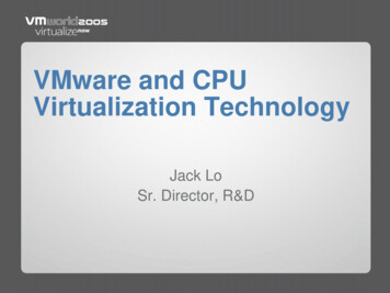
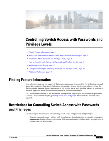
Preparation2.1 RequirementsExample configuration00&0RGH VHOHFWRU/('V,QWHJUDWHG LQSXWV RXWSXWV IRU WHFKQRORJ\6HWWLQJ RI VXSSO\ YROWDJH3RZHU VXSSO\ 21 2))'5,9( &/,40RXQWLQJ UDLO36; &38', '2 352),%86 FDEOH IRU FRQQHFWLRQ WR WKH 03, LQWHUIDFH3URJUDPPLQJ GHYLFH 3* ZLWK 67(3 6 7HFKQRORJ\; ; 352),%86 '3 '5,9(; ; 1R '5,9( &/,4 LQWHUIDFH; ; ; &8 ; ; 6PDUW /LQH 'RXEOH 0RWRU 0RGXOH0RGXOH60& 0RGXOH0RWRU (QFR GHU 0RWRU (QFR GHU TaskConfiguration of an axis using HW Config and S7T Config. You then operate this axis withthe help of a STEP 7 user program.CPU 317T-2 DP: Controlling a SINAMICS S120Getting Started, 12/2005, A5E00480391-012-3
Preparation2.1 Requirements2-4CPU 317T-2 DP: Controlling a SINAMICS S120Getting Started, 12/2005, A5E00480391-01
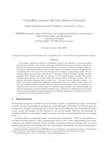
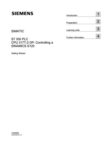
3Learning units3.13.11. Step: WiringWarningYou may come into contact with live wires. Always switch off power before you start wiringthe S7-300.ProcedureA description of the installation and wiring of your 317T-2DP CPU is found in the GettingStarted Collection S7-300 PLC: CPU 31x: Commissioning.Set the PROFIBUS address of the SINAMICS to PROFIBUS address 4. The setting of thePROFIBUS address on the CU230 directly via the hardware DIP switch, is performed in thefollowing way:&RQWURO 8QLW Figure 3-1Schematic representation of the CU320 control unit①PROFIBUS interface②PROFIBUS diagnostics LED "DP1"③PROFIBUS address switchCPU 317T-2 DP: Controlling a SINAMICS S120Getting Started, 12/2005, A5E00480391-013-1
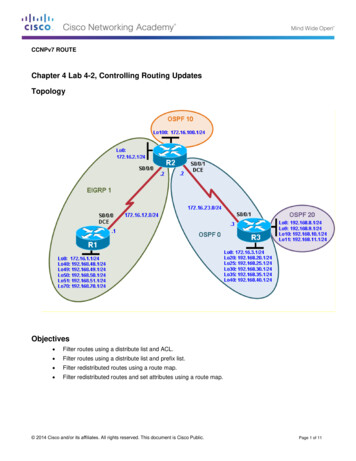
Learning units3.2 2. Step: Configuring CPU 317T-2 DP with HW Config352),%86 LQWHUIDFH GGUHVV3.23.22. Step: Configuring CPU 317T-2 DP with HW ConfigProcedureSequenceActivityResult1Create a new project in the SIMATIC Manager (for example,"GS 317T2-DP with S120") and add a SIMATIC 300 station.The SIMATIC 300 station appearsin the SIMATIC Manager.2Open HW Config by selecting the "SIMATIC 300" station and doubleclicking "Hardware".HW Config opens.3-2CPU 317T-2 DP: Controlling a SINAMICS S120Getting Started, 12/2005, A5E00480391-01
Learning units3.2 2. Step: Configuring CPU 317T-2 DP with HW ConfigSequenceActivity3Open the "Hardware Catalog" and select the "SIMATIC Technology CPU" hardware profile in the "Profile"drop-down list.ResultResult: The "SIMATIC Technology" directory is displayed.4Insert a mounting rail using drag-and-drop in the station window ofHW Config.This creates a mounting rail.5Drag-and-drop the "PS 307 5A" power supply module onto themounting rail.The power supply module appearson the mounting rail.6Add the Technology CPU to the mounting rail by means of drag-anddrop.A message box appears.You change the transmission rate in the next step.In the next dialog box, you can setthe PROFIBUS properties of the DP(DRIVE).7Confirm the message box with "OK.“8Confirm the default settings of the PROFIBUS configuration with"OK".CPU 317T-2 DP: Controlling a SINAMICS S120Getting Started, 12/2005, A5E00480391-013-3
Learning units3.3 3. Step: Changing the transmission rate at the MPI/DP interfaceSequenceActivity9Add a digital input module and a digital output module.ResultYou now have this layout:3.33.33. Step: Changing the transmission rate at the MPI/DP interfaceProcedureSequenceActivityResult1Open the MPI/DP interface (X1) in HW Config with doubleclick.The "Properties - MPI/DP" dialog box opens.2Click "Properties".The "Properties – MPI interface MPI/DP"dialog box opens.3Click MPI(1), then click "Properties".The "Properties - MPI" dialog box opens.3-4CPU 317T-2 DP: Controlling a SINAMICS S120Getting Started, 12/2005, A5E00480391-01
Learning units3.4 4. Step: Vital settings in your DP (DRIVE) configurationSequenceActivity4Select the "Network settings" tab and select a transmissionspeed of "1.5 Mbps".5Confirm all open dialog boxes with "OK".You have now increased the configuredtransmission speed of the MPI interface atthe CPU in order to accelerate data transfer.6When the CPU is in STOP, select PLC Download todownload the configuration. Select the CPU and confirmwith "OK".The "Select node address" dialog boxopens.Confirm with "OK".The data are now downloaded from thePG/PC to the CPU.73.43.4ResultThe default transmission rate of the MPIinterface is 187 kbps, i.e. the PG/PCinterfaces must be set up as describedearlier in the requirements section.4. Step: Vital settings in your DP (DRIVE) configurationProcedureSequenceActivityRes
– CU320 control unit with TB30 terminal board (6SL3040-0MA00-0AA1) – Smart line module, 5 kW (6SL3130-6AE15-0AA0-Z) – Single/double motor module, 3 A (6SL3120-2TE13-0AA0-Z) – 1 synchronous motor 1FK7022-5AK71-1AG3 with incremental encoder sin/cos 1 Vpp via SMC20 sensor module cabinet (6SL3055-0AA00-5BA1) – 1 synchronous motor 1FK7022-5AK71-1LG3 with DRIVE-CLiQ interface: