Transcription
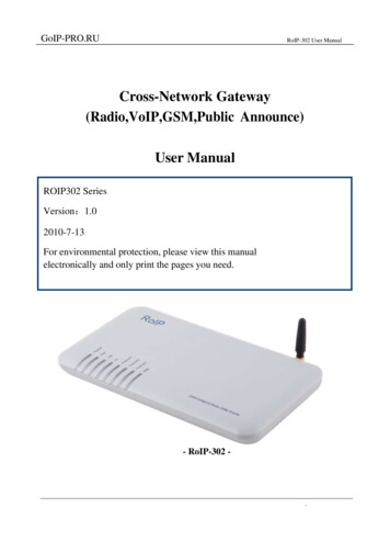
GoIP-PRO.RURoIP-302 User ManualCross-Network Gateway(Radio,VoIP,GSM,Public Announce)User ManualROIP302 SeriesVersion:1.02010-7-13For environmental protection, please view this manualelectronically and only print the pages you need.- RoIP-302 -
GoIP-PRO.RURoIP-302 User ManualContentI. Important Notices . 3II. Gift Box Check List . 4III. Overview . 5IV. Installation . 10V. Default Factory Settings. 13VI. Device Configuration Via Built-in Web Server . 14VII. Call settings. 19VIII. Initiating a Cellular Call . 24IX. Application Examples . 25X. Hardware Specifications . 31
GoIP-PRO.RURoIP-302 User ManualI. Important Noticesi. This product is used to link up the civilian radio network, internet, and cellular phonenetwork. Its operation and performance rely on the broadband network connections via privateand/or public networks and the cellular phone networks. Due to the stability and reliability of thesenetworks, this product may not be able to link up all the networks connected without anyinterruptions. Therefore, it is not recommended to use this product in an emergency system or acommunication system with zero-failure.ii. This product can bridge and extend radio networks all over the world. Please consult yourlocal regulations in order to use this product legally.iii. This product requires the use of dynamic DNS (DDNS) service. For testing purpose, thisDDNS service is temporary provided for free by DBL Technology (Hong Kong). However, thisservice is not guaranteed without any interruptions. Customers are urged to build their own DDNSserver or obtain this service from a DDNS provider. Free DDNS server software may be obtainedfreely from your local network service provider.iv. Customers and/or users are taking full responsibilities and all risks in using this product. Weare not responsible for any direct or indirect losses caused by, but not limited to,communicationfailures as a result of product failure or network problems.CUSTOMERS ARE ASSUMED TO HAVE READ AND ACCEPTED WITH FULLUNDERSTANDINGS OF THE IMPORTANT NOTICES STATED ABOVE.
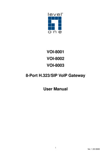
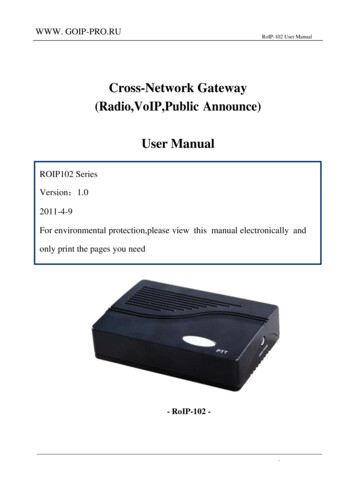
GoIP-PRO.RURoIP-302 User ManualII. Gift Box Check Listi. Upon unpacking the gift box,please check carefully that all items listed below areincluded.Please report to your supplier for any missing items immediately.3 PPT Adapter Cables1 AC/DC AdapterInput:110/220 VACOutput:12VDC,2A1 Main Unit1 Ethernet Cable
GoIP-PRO.RURoIP-302 User ManualIII. OverviewThe fundamental of RoIP(Radio over IP)technology is to convert the audio and PTT signals ina radio terminal into IP packets and then transmit the data via the IP networks. The challenge in thistechnology is to insure that the audio is transmitted in real time and the PPT control signal is transmittedimmediately and reliably. The radio range is general limited by the restricted transmitting power,the antenna sensitivity, and other environmental factors. The success deployment of this technologyextends the coverage of a radio network without using expensive repeaters or links up multipleradio networks in the world. In addition, this technology can also link up the radio world to theVoIP world and the cellular world easily. It truly makes voice communications across multiplenetworks possible.RoIP302 series is developed based on VoIP technology to realize RoIP functions in order tocreate a new type of gateway to bridge voice communications across multiple networks (Radio,Cellular, VoIP). Its main advantages are low bandwidth usage, high fault tolerant, low loss in voicequality, fast response, easy installation and configuration. It is ideal for setting up a private networkwith multiple voice communication platforms, a distributed network for remote management, anetwork with extended coverage, and an integrated network of multiple amateur radio networks.RoIP302 Series Cross-Network Gateway has 3 PTT interfaces. Up to 3 audio channels fromradio networks can be connected to the RoIP302 simultaneously. All 3 channels can beprogrammed into the same or different groups in order to bridge real time voice communications tovarious network interfaces.RoIP302 Series has a built-in GSM / CDMA cellular phone module, user can access the radionetworks connected via the cellular network installed. A radio terminal equipped with DTMFgeneration capability can make an outgoing call via the cellular network as well. This links up thetwo networks which cannot be linked up via any traditional means.RoIP302 Series gateway can also be a remote ON/OFF Switch. User can control the built-inrelay to switch on or off the devices that are under control. These devices could be an alarm signal,alight, a public announce system, an electronic lock, etc.RoIP302 Series gateway supports routing of IP voice stream to via a recording server. Voicerecords can then be saved to a hard disk and can be retrieved at any time for examinations.RoIP302 Series gateway can be installed in IP networks with intranet or internet connectionsvia ADSL modem, Cable modem, or Local Area Network (LAN). The unique built-in DDNS clientcan help to simplify the installation and configuration without relying on a voice relay server inorder to achieve interconnections among RoIP302 Series gateways.
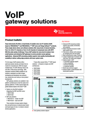
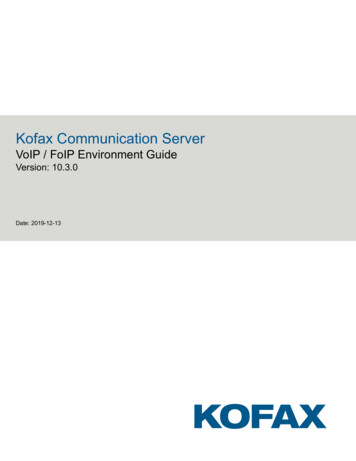
GoIP-PRO.RURoIP-302 User Manuali. Theory of OperationThe diagram below shows the concept of how RoIP bridge the voice communication two radioterminals at two different locations. The PTT Interface Cable provided is used to connect betweenthe RoIP and the radio terminal. Please note how the signals are passing between these two devices.The connection between the two RoIP302s is through internet or intranet. The green lines actuallyshow how the audio and the PTT control signals are transmitted between the two radio terminals.The two RoIPs have created a virtual connection between the two radio terminals.ii. Modes of OperationWith different options, RoIPs support both Point-to-Point Mode and Group Transmit Modeoperations. Please refer to Section 3.4 for more RoIP versions available.There are two types of RoIPs: RoIP302 and RoIP302M. RoIP302s cannot only support Pointto-Point operation. RoIP302M has a built-in SIP server for 12 clients (RoIP302 can only supportone client) and group transmit capability. The additional feature in RoIP302M is the built-in SIPserver and the ability to transmit voice signal a maximum of 12 SIP Clients simultaneously.a. Point-to-Point ModeIn this mode, one RoIP302 is using public IP and the others could use public IPs of private IPswith DDNS enabled. If the built-in SIP server is used, either one of the RoIPs can be a master andthe other will register to the master. Please make sure that both RoIP302s do not have the sameGroup SIP Number.
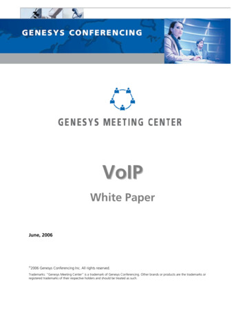
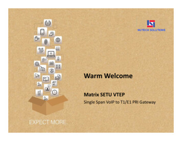
GoIP-PRO.RURoIP-302 User ManualThe diagram below demonstrates each RoIP302 are connected to 3 Radio Terminals. Eachterminal is assigned to a different group. The two RoIP are connected via a IP connection as shownby the blue line. The PTT control signal is represented by the single purple lines and the voicesignals are represented by the double purple lines. When a voice transmission is initiated from achannel, the RoIP302 will connect to the other RoIP302 in order to establish a link with thecorresponding channel automatically.b. Group Transmit ModeAt least one RoIP302M is required to support the Group Transmit mode. This RoIP302M is themaster with its own unique Group SIP Number and offers its built-in SIP server for up to 12RoIP302s (RoIP302M can also register as well for expansion) to register. The diagram below showsonly RoIP302s are used to register to the RoIP302M. Each RoIP302s must have its unique GroupSIP Number. A maximum of 12 RoIP302s can be deployed in this example. Please note that onlyone one-way voice transmission is allowed at all time.When a voice signal is transmitted from a RoIP302, RoIP302M will re-transmit the signal to allother clients in the same group. If the voice signal is coming from a PTT port (radio terminal) of theRoIP302M, the RoIP302M will re-transmit the voice signal to all other PTT ports and SIP clientsthat are in the same group. For example, if Channel 802 talks, Channel 701, 803 and 804 can hear.If Channel 701 talks, Channel 802, 803, and 804 can hear.Please note that when more channels are used, the higher bandwidth is required and the poor
GoIP-PRO.RURoIP-302 User Manualthe performance of the system is. It is recommended that the user needs to insure sufficientbandwidth is available and the network connection is stable before implementing a large network.In general, intranet network is preferred in this case.iii. Application ExamplesApplication example 1: Link up radio network between two locations-Using two RoIP302Gs to link up three radio channels in two different locations.
GoIP-PRO.RURoIP-302 User ManualApplication example 2: Link up radio network at multiple locations-As shown in the application diagram above, four locations can be linked up via oneRoIP302GM and three RoIP302G. The RoIP302GM has a built-in SIP server and the group transmitcapability to up to 12 SIP clients. By replacing one RoIP302G with RoIP302GM, the system is now inGroup Transmit Mode and up to 11 more RoIP302Gs can be added to the system. Each RoIP302G nowregisters to the RoIP302M. This mechanism allows the system to expand rapidly.iv. Model Nomenclature
GoIP-PRO.RURoIP-302 User ManualIV. Installationi. Back PanelLabel1NameSwitchDescriptionRemote control: Relay switch with 220VAC inputand 500 mA load current.2Channel 36-pin RJ11port for PTT Adapter Cable3Channel 26-pin RJ11port for PTT Adapter Cable3Channel 16-pin RJ11port for PTT Adapter Cable5ResetPress 10 seconds to reset the device to factorydefaults.6WAN7LAN10/100Base-TWAN connection for externalaccess10/100Base-T LAN connection8Power12V 1Aii. LED IndicatorsLEDPowerRUNFunctionPwoerRoIP StatusLANLAN port statusDescriptionLights up when the power is connectedFlashes every 250ms indicates the device is notready.Flashes every 500ms indicates the device is ready.Lights up when the LAN port is connected.Blinks when there are data transmissions.
RoIP-302 User ManualPCPC port statusChannel 1Channel 1Tx/Rx statusChannel 2Tx/Rx statusChannel 3Tx/Rx statusGSM statusChannel 2Channel 2GSMLights up when the PC port is connected.Blinks when there are data transmissions.Channel 1 is receiving / transmitting.Channel 2 is receiving / transmitting.Channel 3 is receiving / transmitting.A GSM call is active.iii. Channel Port Pin AssignmentThe channel port is a 6-pin RJ-11 Socket1、 PTTOUT 2、GND3、Vin(RX) 4、Aout(TX)5、GND6、PTTINiv. PTT Adapter Cable wiring Diagramv. Switch PortThe built-in relay switch is connected to the middle two pinsofthe RJ-11 socket. It acts as an ON/OFF switch for theexternalsystem connected.
RoIP-302 User Manualvi. Main Unit Setupa.Connect the Switch Port to an external system for remote control. It can be used to switchonand off a Public Announce (PA) system to instant broadcast. If the relay switch is connected tohigh voltage load. The maximum rating for the internal relay is 240VAC and 500 mA load current.b.Connect the Channel Port to a Radio Channel via the PPT Adapter Cable provided. Up to 3channels are supported.c.Connect the WAN Port to a router, network switch, ADSL/Cable Modem for access anexternal network or the public network.d.Connect the LAN Port to a local PC or a local Ethernet network (LAN). This allows sharingthe external network connected to the WAN Port with the local network. However, the sharednetwork is intended for configuration the device and is best not used for high data trafficsapplications in order for the device to insure the best voice quality.
RoIP-302 User ManualV. Default Factory SettingsThe table below shows the factory default settings.There are two way to reset to the factorydefault settings:i. Press the RESET switch for more than 15 seconds.ii. In the Configuration paga,select Tools and then Reset Config.ItemFactory Default SettingsRangeLogin IDadminLogin PasswordadminProgrammable(16characters in the ASCIItable)WAN Port SettingDHCPLAN Port Setting192.168.8.1PTT State“0” is active low“0”is active“1” is active high1238 digits or lessGSM Login passwordPTT maximum durationJitter Delay60 seconds60 millisecondsLess than 600 seconds20-220 milliseconds
RoIP-302 User ManualVI. Device Configuration Via Built-in Web ServerThe built-in web server provides a comprehensive way to fully program the device manuallyi. Web Server LoginThere are two methods to access the built-in web server.Method 1 is to access the built-in web server via the LAN port.Connect a computer to the LANport of the RoIP302 and configure its IP to 192.168.8.x(x 2 to 254).Type the IP address 192.168.8.1in the address field of a web browser.The following login window is then displayed.Enter the User name and the password now.The user name for the administrative level is“admin” and the default password is “admin”.Please make sure to click on “Save Changes”after configuring the device.Method 2 is to access the built-in web server via the WAN port.The WAN port is set to DHCPmode as a default factory setting.When it is first connected to a network with a DHCP host,itobtains an IP address automatically from the host.In order to listen to the IP obtained,make a call tothe PSTN number.Once the call is answered,the device plays a voice prompt to ask forpassword.Dial “*00” and the device then reads out the WAN port IP address.Enter this IP in the address field of a web browser to get a login window as described inMethod 1.ii. Status:This is the default page when you first login to the device web server. It consists of
RoIP-302 User Manualthreecolumns and it is important to understand the information shown in this page in order to debugorreport a device problem.a. Left hand column shows the device information and the SIP registration status.b. Middle column shows information on the network configuration and its status.c. Right hand column shows information on the GSM hardware, carrier and channel status.iii. ConfigurationThe page contain all configuration settings for the RoIP. It is subdivided into varioussections/pages for the ease of configuration. The sub-pages include Preference, Network, CallSettings, PTT Settings, GSM Settings, Recorder Settings, Broadcasting Settings, Group CodecSettings, and Group Settings.iv. PreferencesThe Preference page consists of the common settings for the device and is shown below.The mains settings in this page include:
RoIP-302 User Manuala.Language – This specifies the language for the webpage and the voice prompts.Currently, onlyEnglish and Simplified Chinese are supported.b. Time Zone and Time Server – Time Zone is specified as GMT or – a fixed value. RoIPacquires the standard GMT time from the Time Server specified.c. Auto Reboot – This option reboots the device automatically at the time specified.d. .DDNS – When the RoIP is installed in a network environment with dynamic IP and a SIPserver is not used, customer can choose to use our free DDNS service or DDNS offered by otherservice provider.Enable this option to connect to our DDNS service as shown above.The currentsettings are set to connect to our DDNS server (hk.ippcn.com) using port “39980” and the updatetime is 600 seconds.Please note that the DDNS Address cannot be set to other DDNS server; thissetting only works with our own DDNS server. Once this service is used, the domain name for theRoIP is then serial number .com. The serial number is shown on the bottom label.e. Remote Control – This option allows a user to access the RoIP’s webpage directly from ourremote control server.iv. NetworkProper network environment is the key to insure the performance of the RoIP302. normal Forbest performance, it is recommended to connect the RoIP302 to a network with a static IP. Ingeneral, this kind of network access offers higher bandwidth utilization. The next preferred networkaccess method is ADSL / Cable modem with PPPoE dial up for dynamic IP allocation. The worst isthe sharing private network via a router.The performance of RoIP302 depends greatly on thebandwidth usage.In this case, it is best to configure the router to DMZ mode to the IP of theRoIP302.In order to get network access, the LAN port must be configured according to the networkenvironment to be connected. There are 3 access methods available for the LAN portconfiguration.a. Static IP – This mode applies to both public and private IP network environment. In theLAN port configuration shown below, select “Static IP” and then fill in the parameters as providedby your network administrator.
RoIP-302 User Manualb. DHCP – When the RoIP302 is installed behind NAT and a DHCP host is available, selectthis mode will enable the device to obtain LAN IP address and other network IPs automatically.c. PPPoE – For most ADSL and Cable modem access method, the PPPoE dial up is normallyused.If the RoIP is connected directly to an access modem, you may need to select the PPPoE.Please consult your ISP for further information if needed.Fill in the User Name and Password asprovided by your ISP to complete this LAN port configuration.The PC Port allows other network devices to be attached to the RoIP-302 Gateway. It offersboth Bridge and Static IP modes to meet your requirements.The factory preset is Static IP mode with the IPaddress 192.168.8.1.a. Bridge ModeSelect Bridge mode if your network topology requires the network devices (PC or others) to bein the same network segment as the GoIP4 Gateway. In this case, the GoIP4 Gateway functionsas an Ethernet Switch.b. Static IP Mode (Default Setting)Select Static IP mode for a new network segment on PC port.In this case, the GoIP4 Gatewayfunctions as Router. Enter the IP address in IP Address field with a new segment address that isdifferent from that on the LAN port. Enter the subnet mask in Subnet Mask field accordingly.A commonly used value is 255.255.255.0.
RoIP-302 User ManualEnable the DHCP Server if you want the GoIP4 Gateway functions as a local DHCP host onPC port.This will enables the GoIP4 Gateway to assign IP Addresses to network devices that areattached to the PC port.Specify the Starting Address, Ending Address, and Static DNS accordingly.
RoIP-302 User ManualVII. Call settingsThe RoIP302 supports up to 3 groups with a unique Group SIP Number. Each RoIP302 mustdefine at least one group. The Group SIP Number is the only reference between a group and thePTT ports.If the RoIP is connected to a SIP server, then this number is assigned by the SIPserver administrator.If a peer-to-peer configuration is used, then this number must be unique and isassigned by the user arbitrary.For SIP Proxy mode, each RoIP302 are designated as a terminal.The table below describes howto program the key parameters. Other parameters should be programmed as required by the SIPproxy.Group SIP NumberSIP ProxyAuto Dial NumberSIP Proxy Mode SettingsRoIP302 TerminalAssigned by the SIP ProxyadministratorSIP Proxy IP or domain nameThe Group SIP Number of the RoIP for voiceconnection to be established when a PPT signaldefined in the PPT Setting is active.For peer-to-peer mode, only two RoIP302s are used for interconnection. One RoIP302 isdefined as a Host which supports a proxy mode for other RoIP302 (referenced as terminal) toregister.The table below describes how to program the key parameters.
RoIP-302 User ManualPeer-to-Peer Mode SettingsRoIP302 HosRoIP302 TerminalGroup SIPNumberSIP ProxyAuto Dial NumberUnique number assigned by theuserUnique number assigned by theuserHost IP or DDNS if enabledHost IP or DDNS if enabledBlankThe Group SIP Number of theRoIP for voice connection to beestablished when a PPT signalis active as defined in GroupSettings (Section x.x).The Auto Dial Number is basically the number that the RoIP302 automatically makes a call towhen a PPT signal is active as defined in the Group Settings (Section x.x).i. PTT Settings:This section defines the PPT Signal settings. RoIP302 supports up to 3 PTT ports and each PPTconsists of two control signal (PTT Input and Output). Difference radio terminals may havedifferent requirement on the PTT control signals. Please consult the User Manual of your radioterminal for more information.a. Input Active Level defines the active level for the PTT Input.Select “1” if the PTT Input isactive when the electrical level is high ( 5V).Select “0” if the PTT Input is active when theelectrical level is low (0V).b. Output Active Level defines the active level for the PTT Output.Select “1” if the PTTOutput is active when the electrical level is high ( 5V).Select “0” if the PTT Output is active when theelectrical level is low (0V).c. PTT Output Expiry (s) defines the maximum duration in second for the PTT Output to beactive. This means that the maximum transmit time for a voice channel is limited by the PTTOutput Expiry.This method is used to prevent a radio terminal to occupy the voice channelindefinitely. The minimum value is 30.
RoIP-302 User Manualii. GSM SettingsThe GSM settings in this section mainly define the password for incoming and outgoing GSMcalls.If it is left blank, then no password is required.The voice activation detection settings are listed below. This firmware version does not supportthis feature yet.iii. Recorder SettingsThe recording settings define the address of the recording server for each group.Please refer tothe RoIP Voice Recording User Manual for more information.iv. Public Announce (PA) SettingsThe RoIP302 provides a relay switch to control a PA system. When the RoIP302 receives thePA ON Password, it turns on the relay to activate the PA system. Audio is transmitted to the PAsystem at this time. When the RoIP302 receives the PA OFF Password, it turns off the relay todeactivate the PA system. The duration for the relay to be in the ON state is limited by the value setin the parameter PA ON Expiry. This mechanism shuts down the PA System automatically. The PAControl Group defines which group has the control over the relay switch. Only the radio terminalsin the group specified can broadcast to the PA System.
RoIP-302 User Manualv. Group Codec SettingVoice codec is commonly used in voice over IP communications.It enables voice to becompressed in order to save the transmission bandwidth. The higher the compression rate is, the low thetransmission bandwidth is required. However, the voice quality is degraded as the compression rategoes higher. In general, a-law, μ-law, and G.729 are commonly used. The transmission rate of a singlevoice channel is about 82Kbps for a-law or μ-law and about 26Kbps for G.729. However, when aradio station is required to transmit voice data, only a-law or μ-law codec should be selected for noloss in voice quality.It is important to note that all users in the same group must use the same codec.vi. Group SettingsThe Group Settings assigns the radio channels (3 PTT Ports) and the GSM channel to one of the threegroups available. Once a channel is assigned, it cannot be assigned to another group.In the diagram below, all 4 channels are assigned to Group 1. This means that there are nochannels left for Group 2 and 3. In this case, RoIP302 can only support one group operation.However, for RoIP302M/RoIP302GM , Group 2 and 3 can be used as a conference bridge for otherRoIP302s. Please note that the web interface does not check for duplicate selection among groups.Please make sure that each PTT or GSM channel can only be assigned to a group no more than onetime.vii. Save ChangesPress “Save Changes” on the left column to save all changes made. The web server will notremind you when you exit.viii. The Online Upgrade selection is the first item in the Tools menu. Please check regularly
RoIP-302 User Manualwith your supplier or our website (www.dbltek.com) for the latest firmware release.
RoIP-302 User ManualVIII. Initiating a Cellular CallThe model RoIPx02G and RoIPx02GM have built-in GSM module to enable voicecommunication with the radio channels that belong to the same group. This means that a telephoneuser can dial in to the RoIP to conduct a voice call with the radio channels. A radio terminalequipped with DTMF capability can also dial out to the telephone network to conduct a voice call.The ability to communicate with other voice networks makes the RoIP302 a truly “Cross-platformGateway”. Below are the procedures to initiate a voice call.i. Initiate a call from the telephone network to the radioUse a PSTN or Cellular phone to call the phone number of the SIM card that is installed on theRoIP302. Once the RoIP302 answers the call, it generates a voice prompt to ask the caller to enterthe GSM IN Password (described in Section 7.7) and then press the “#” key. The default passwordis “123”. Once the correct password is entered, RoIP302 generates double beeps as confirmation.The caller can then hear the voice communications of the group that the GSM Channel is assignedto. Please note that only one way voice communication is allowed. The caller should wait for asilent period before enabling the voice channel to talk. To enable the voice transmission, the callerneeds to press the “*” key to enable the PPT control before talking. Once the caller completes theconversation, he/she should press the “#” key to disable the PTT control in order to deactivate thevoice transmission. Therefore, the Radio party can talk back. This mechanism simulates the PTTmethod used in Radio Communication.Please note that when the “*” or “#” key is pressed, the caller should hear a confirmation tone(double beeps). If the caller does not hear this tone, he/she should dial the digit again. The callercan just hang up the phone to end the call.ii. Initiate a call from the radio to the telephone networkTo initiate a call via the GSM channel, the radio user should press and hold the PTT button toactivate the transmission and the dial the following sequence. password “#” phone number “#”where the password is the GSM OUT Password as described in Section 7.7. Please make surethat the PTT button is pressed while dialing the sequence. Once the RoIP accepts the dialed sequence, it willthen play the voice prompt of “Dialing in Progress”. Once the call is answered, the RoIP will then broadcasta voice prompt of “Call connected” to the radio caller.Since the called party may not know the call is coming from a Radio party, the mechanism used in 1cannot be used. Instead, the voice activated detection (VAD) mechanism is adopted. When there is no voiceactivities on the radio side, voice signal at the telephone side will be transmitted. Therefore, bothsides will have to adapt to this talking method in order to conduct a normal conversation.
RoIP-302 User ManualIX. Application ExamplesExample 1: Linking up two MOTO GM300 Radio terminals in peer-to-peer mode with twoRoIP302/RoIP302G. The network access method is ADSL.Operating procedures:i. Connect the PTT Interface of the radio terminal (GM300) with the PTT Interface Cable asshown in the diagram below. Connect the RJ-11 plug of the PTT Interface Cable to PTT1 port ofthe RoIP302.ii. Connect the RoIP302 LAN port to an Ethernet port of the ADSL Routeriii. Assign a fixed IP to the RoIP302 LAN port. This fixed IP must be in the same segment asthe LAN port of the ADSL Router.For example: if the LAN of the ADSL Router has an IP192.168.1.1, then the LAN port RoIP302 could be set to 192.168.1.101.iv. Configure the DMZ mode of the ADSL Router to fixed IP assigned to the RoIP302 LAN port. ForDMZ configuration, please refer to the User Manual of the Router.v. Login to the RoIP Webpage and program the Network Settings as shown below.Please note that the DNS addresses should be programmed as provided by from your local ISP.vi. Next go to the PTT Setting page and set both PTT Input and Output to active low asshown below.
RoIP-302 User Manualvii.Assign the RoIP302 at Location A to be the master and a Group SIP Number as 101.viii. Go to the Preference Page and enable the DDNS feature. If the serial number of the RoIP302 isRoIP30220100610005, then the DDNS settings are shown below.ix.Next go to Call Settings page and configure it as shown below.x.Configure the Group Settings as shown below. Since the PTT Interface Cable isconnected to PTT1 port and there are no devices connected to PTT2 and PTT3 ports, only PTT1port is assigned to Group 1. Select the GSM channel as required.Please note that the RoIP302 atlocation B should have the same Group Settings as the one at location A. This means that the PTT1port is assigned to Group 1 for both RoIP302s.xi.The last thing to configure is the Codec Settings. Choose a-law or μ-law for best voiceperformance. Please make sure that both RoIP302s use the same codec.
RoIP-302 User Manualxii. Next configure the RoIP302 at location B. First, go to the Preference Page to enable theDDNS feature. If the serial number of the RoIP302 is RoIP30220100610006, then the DDNSsettings are shown below.xiii. Next configure the Call Settings page as shown below. Please note that it has a differentGroup SIP Number as the one in location A. Plea
GoIP-PRO.RU RoIP-302 User Manual ROIP302 Series Version:1.0 2010-7-13 For environmental protection, please view this manual electronically and only print the pages you need. Cross-Network Gateway (Radio,VoIP,GSM,Public Announce) User Manual - RoIP-302 -