Transcription
SolarMax 2000S/3000S/4200S/6000SDer Wechselrichter für netzgekoppelte Solarstromanlagen n The inverter for grid-connectedPV installations n L’onduleur pour les installations électriques solaires couplées au réseau nEl inversor para sistemas de electricidad solar conectados a la red n L’inverter per impiantisolari di corrente collegati alla reteGerätedokumentation n Instruction Manual n Documentation d’appareil nDocumentación del dispositivo n Documentazione Product SafetyTYPEAPPROVED
IntroductionThank you for choosing a SolarMax solar inverter!SolarMax converts the direct current from your solar system into grid-compliantalternating current.As a solar system operator you expect reliability and high yield from your system.With our SolarMax range we offer inverters that fully meet these requirements. TheSolarMax inverter range is characterised by high efficiency and high availability.enThe inverters carry the CE mark as an indication of compliance with EuropeanUnion Directives.The “Type Approved” quality mark from TÜV Rheinland confirms compliance withall relevant safety standards.Headquarters of Sputnik Engineering AG in the former Rolex building in Biel,the Swiss watch metropolis.The ManagementSputnik Engineering AGHöheweg 85CH-2502 Biel/BienneE-Mail: sputnik@solarmax.com5305/08SolarMax string inverter: powerful, reliable, innovative.54
Introduction541Safety instructions572Installation2.1 Installation2.2 Electrical connection2.3 Overvoltage protection2.4 Switching on and off2.5 Removal2.6 Configurable limit values and operational settings2.7 Heat sink temperature limit2.8 Initial setup2.9 Status signalling contact58586164656566676768Auto Test3.1 Auto Test definition according to DK 5940 (Italy)3.2 Start Auto Test3.3 Procedure70707071Operation and fault display4.1 Graphics display4.2 LED display4.3 Menu key symbols4.4 Menu structure4.5 Communication activity4.6 Status messages4.7 Alarm ooting5.1 Introduction5.2 Troubleshooting via the graphics display5.3 Maintenance868687906Data communication917Technical description7.1 Technical configuration SolarMax 2000S/3000S7.2 Technical configuration SolarMax 4200S/6000S7.3 Safety functions7.4 Control functions7.5 Technical data SolarMax 2000S/3000S7.6 Technical data SolarMax 4200S/6000S7.7 Glossary7.8 Efficiency9393939494959697988Warranty8.1 Warranty8.2 Prolongation of guarantee8.3 Limitation of liability and warranty8.4 Applicable law8.5 Place of jurisdictionen10010010110110110156
1 Safety instructions2 InstallationSolarMax inverters operate with high DC voltages. The complete systemmust therefore be installed with great diligence, following all relevantregulations. Contact with live parts can cause critical injuries or death.Only suitably qualified personnel may connect the SolarMax inverter tothe mains. The installer must be approved by the relevant energy utilitycompany.The maximum solar generator output can be found in the data sheet.enWarning: The device may only be opened in de-energised state (AC and DCside). Wait for five minutes to allow the capacitors to discharge.2.1 Installationn SolarMax inverters may be installed only by qualified electricians.The device should be installed and connected with the cover closed. SputnikEngineering has developed a mounting rail in order to simplify the installation. Twozinc-plated wall screws (6 x 50 mm) and two wall plugs are included. First installthe mounting rail on the wall. The SolarMax inverter can then be pushed onto themounting rail. Fasten the inverter at the left and right of the mounting rail with twoM6 x 12 screws.n Please do not commission the device if the casing is damaged or you arenot sure whether the device is working properly! Immediately disconnectthe device from the mains and from the solar generator!n Before opening the SolarMax device, the DC and AC feed lines must bedisconnected.n Large arcs may be generated if connectors are disconnected on the DC side during operation. The DC cable must therefore be disconnected before removingthe MC connectors by means of the DC insulation switch on the left-hand side ofthe inverter.n Caution: The discharge duration of the capacitors is 5 minutes.n Please follow the detailed installation instructions in Section 2.n Failure to observe the installation instructions will void any warranty andliability.n Disconnect your SolarMax inverter from the mains by disconnecting the AC feedline before carrying out any maintenance and cleaning on the solar generator.5705/08n Please follow the general local installation regulations.58
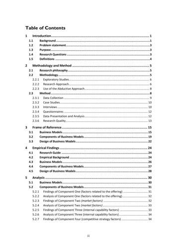
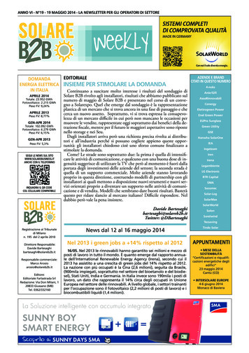
545 mmis made from cast aluminium, which ensures adequate cooling via convection andan additional fan.522 mmPlease note:n The SolarMax may only be operated in an overvoltage category II AC installation!If this is not the case, additional overvoltage-limiting elements (varistors) mustbe installed at the network connection point.290 mm1n If the SolarMax device is installed inside a building, the space should be wellventilated.enn The inverter must be mounted on a solid surface.n For flammable surfaces an additional fireproof panel must be used, since theheat sink may reach temperatures of up to 80 C.n Please refer to the technical data for the maximum permissible ambient temperature.n For optimum cooling the following distances should be adhered to: 0.5 m above,0.5 m below, 0.3 m at the sides.n Multiple devices should be installed above each other, if possible. For side-byside installation the minimum distance between devices should be 0.5 m. Ifdifferent SolarMax models are used, they should be installed in the followingorder (top to bottom): SolarMax 2000S, SolarMax 3000S, SolarMax 4200S,SolarMax 6000S.4351 Graphics display with operation2 AC connectorn In external installations direct sunlight should be avoided. A protected installation location, for example under a canopy or a solar module, would be an advantage. The device should also be protected from splashing, for example rainwaterdripping off roof or module edges.2n The inverters must not be installed in cabinets, enclosed recesses or similarlocations.4 DC insulation switch5 Status signalling contact3 DC connectorn Do not store flammable liquids near the inverter. Do not subject the inverter toflammable gases or vapours.The SolarMax housing meets the requirements of protection type IP 54 and is suitable for outdoor installation. Protection rating IP 54 is only met if the enclosed ACconnector and the solar generator are connected via the MC-4 connectors.n The inverter must be positioned out of reach of small children.n The inverter and the supply lines must be installed such that they are inaccessible to pets (especially rodents).In order to maximise the energy yield it is important to position the inverter correctly. The lower the ambient temperature, the more efficiently the inverter willoperate.5905/08Notwithstanding the high efficiency of the SolarMax inverter, approx. 5 % of thepower has to be dissipated in the form of heat. To this end the base of the devicen Due to noise emission it is advisable to avoid installation in living areas.60
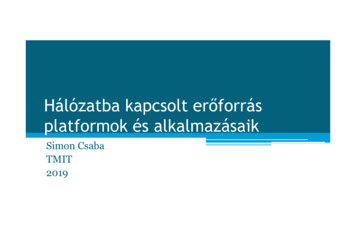
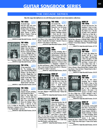
2.2 Electrical connectionAssembly of the AC cable socketSputnik Engineering supplies the SolarMax inverters prewired and ready for connection. All connections are pluggable. The device therefore does not have to beopened.SM2000S/ 3000S/4200S/ 6000S:Rear part of socketThe following connections are available:Socket insertn DC: 3 x 2 MC4 sockets (3 strings with MC4 connectors)n AC: Wieland flange connectorn Communication: 2 x RJ45 (sealed with protective caps)Screwed cable glandn Status signalling contact M12 connectorenSM2000S/3000S/4200S/6000SEnsure that the cable is de-energised.n Connect the AC cable socket with a flexible cable according to EN60309-2 /VDE 0623. Strands with a max. cross-section of 4 mm2 can be connected.n Push the rear part of the socket over the cable.2 x RJ45 socketsData communicationWieland flange connectorAC feed lineStatus signalling contact3 x 2 pairs of MC4 connectorsDC feed linen Press wire end sleeves onto the stripped strands.n Connect the individual wires with the insert in turn as follows(Strand cross-section: see table on page 63)Protective earth conductor PE with the screw terminal with earthing symbolNeutral conductor N on screw terminal with the label NPhase L on screw terminal with the label LTightening torque 0.8 – 1.0 Nmn Ensure that the wires are connected properly.If the RJ45 sockets are used and the inverter is exposed to the weather, pleaseuse products from the VARIOSUB-RJ45 range with IP67 protection from PhoenixContact. This ensures that the installation meets the requirements of IP54.n Snap the rear part of the socket onto the socket insert.n Tighten the screwed cable gland.n RJ45 connector, 8-pin, quick connector system (art. no. 1658493)n Pre-assembled Ethernet cable, 8-pin RJ45/IP67 on RJ45/IP67 (art. no.1658480-)6105/08Available from www.phoenixcontact.com.62
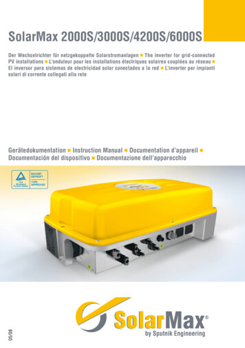
Large arcs may be generated if connectors are disconnected on the DC orthe AC side during operation. The AC supply and the DC insulation switchmust therefore be disconnected before removing the connectors.Back-up fuses and cable cross-sectionsFollow the generally accepted state of the art. Start on the AC side.AC side:Earthing (second protective earth connection)Each inverter must be protected separately! No consumers may be connected between the fuse and the inverter!TypeBack-up fuse(characteristic C)Minimumcable cross-section (strand)2000S3000S4200S6000S10 A13 A20 A25 A1.5 mm21.5 mm22.5 mm22.5 mm2enWe recommend using larger conductor cross-sections in order to minimise linelosses.Without a connection to the solar generator the stray current of the inverter is lessthan 3.5 mA on the AC side. However, during operation of the solar generator, thestray current at the inverter may far exceed the value of AC 3.5 mA. In this case asecond, fixed protective earth connection according to EN 50178 is required. Thecross-section of the second protective earth conductor should have at least thesame cross-section as that of the main terminal. A second protective earth conductor can be connected below the status signalling contact.The flexible cable is connected to a junction box with a maximum length of onemetre. From here the installation may be continued with a rigid TT cable.DC side:Select the cable cross-sections on the DC side to suit your system configurationand in accordance with the relevant installation regulations.2.3 Overvoltage protectionSolarMax inverters feature integrated surge protectors at the input and output. Onthe DC side 2 surge arresters (varistors) for the plus and minus terminal to earthare installed. On the AC side a surge arrester (varistor) is installed between thephase and neutral. All surge arresters meet the requirements of class D accordingto VDE 0675-6 or Type 3 according to EN 61643-11.General information:n When connecting several SolarMax devices, distribute the inverters over thethree mains phases.n AC and DC cables must be suitable for the expected loads, currents and ambientconditions (temperature, UV, etc.).Note the following if the overvoltage protection on the DC is to be increased:n The personal protection regulations must be followed when the inverter is connected to the AC system.n For inverters without galvanic isolation the DC terminals have a potential relative to earth that may be higher than the peak value of the mains voltage. Forthis reason, the response voltage of the surge arrester must be higher than600 Vpeak .n Ensure that the mains cable is de-energised before connecting the device.n Verify the polarity before installing the DC side.n Ensure short circuit- and earth-leakage-proof connection of the DC cables to theMC terminals.n Caution: Due to the earth-fault monitoring function, neither the minus nor theplus terminal should be earthed. Otherwise the integrated insulation monitoringfunction would prevent grid feeding.n Connect the DC side via the MC connectors.05/0863 600 V 600 VSolar generatorThe diagram on the left shows theconnection of additional surge arresters on the DC side.64
2.4 Switching on and off2.6 Configurable limit values and operational settingsn All SolarMax inverters operate fully automatically and maintenance-free. Theisolating switches between the solar generator, the inverter and the 230 V mainssupply remain on at all times. SolarMax will start and transfer power to the230 V grid when the irradiance is high enough. Otherwise the device remains instandby mode and is thus available for grid feeding at all times. Overnight theelectronic system is disconnected from the mains.In the SolarMax S series the following parameters can be set manually via the interface with the MaxTalk software. The settings are password-protected. A passwordapplication form can be ordered via the SolarMax hotline. The password is onlymade available to installers who sign the form. The password is not made availableto private individuals or system operators.ParameterVoltage may only be applied on the DC and AC side of the SolarMax withthe device closed.UnitRegional settingsDE/CHITESFROtherVac maxV264274253264300Vac minV184186196196184Switching on:f maxHz50.250.35150.555n Switch on DC insulation switch.The graphics display powers up.During the night or at times of insufficient irradiance the graphics display turnsitself off (no energy consumption).f minHz47.549.74849.545Hz/sNA0 (Inactive)NAV253mA300300A10.5% ofIac rated*df/dt maxVac 10min maxIerr maxn Switch on the AC isolating switch (may be fused).Iac mean maxPasswordprotectedsetting184 30045 55NANA0.1 1264264243 26430030030050 3001110.05.10 (Inactive)Switching off:Restart delays00180000 600n Switch off the AC insulation switch.Pac maxSM2000SW19801980198019801980990 1980Pac maxSM3000SW275027502750275027501375 2750Pac maxSM4200SW418041804180418041802090 4180Pac maxSM6000SW506050605060506050602530 5060Iac maxSM2000SA12121212126 12Iac maxSM3000SA12121212126 12Iac maxSM4200SA19191919199 19Iac maxSM6000SA222222222211 22Large arcs may be generated if connectors are disconnected on the DCside during operation.n Switch off the DC insulation switch.Graphics display switched off.2.5 Removaln The device does not have to be opened for demounting.n The inverter must be de-energised. First disconnect the device from the mainson the AC side via the AC line protection breaker or the fuse. Then open theDC insulation switch in order to disconnect the inverter from the solar generatorfield. Now remove the connectors.NA: not availablen Before releasing the screws ensure that the bottom of the device (heat sink) hascooled sufficiently to allow the device to be safely handled.en* Iac max 1.1 x Iac ratedThe set values can be queried via the display in the main menu (see section 4.4).6505/08n Release the two locking screws on the left and right and remove the inverterfrom the mounting.66
2.7 Heat sink temperature limitImportant: The country must match the location of the inverter in order toensure that the inverter operates within country-specific limit values.For safety reasons the temperature of the heat sink is limited to 80 C. At ambienttemperatures of more than 45 C the heat sink temperature may reach 75 C. Inthis event the maximum inverter output is reduced temporarily. If the temperaturerises above 80 C the device switches off automatically in order to prevent thermaloverload.Correct setting of the country ensures that the inverter operates within country-specific limit values. If the selected country does not match the actualinstallation site the inverter will load incorrect limit values.This may invalidate the ESC operating licence for the inverter.2.8 Initial setupThe “Initial Setup” starts automatically when the inverter is switched on for thefirst time. This procedure only has to be completed when the device is commissioned for the first time. To start with, English text appears inviting you to selectthe required language. The subsequent setup messages will then appear in the selected language. Then select the installation country. In the third step please checkthe date and the time and correct if necessary. The date set here is stored as thecommissioning data and can be retrieved via the “Information” menu. All settings(apart from the country setting) can be modified later via the “Settings” menu.The initial setup is still concluded with the2.9 Status signalling contactThe status signalling contact is used for remote monitoring. The potential-freerelay contact enables the status of the inverter to be monitored. The contact islocated at the front of the unit between the DC and AC ports.The functionality of the status signalling contact can be set in the Settings menuas follows:key.SettingOffMainsErrorConfirm the installation country with thekey.The events that may trigger the status signalling contact are listed in Section 4.6Status messages.key. “Initial setup” will start again.05/0867FunctionThe status signalling contacts are deactivated (remain in inactivestate).In mains mode the NO status signalling contact closes immediately and is opened again with the set delay as soon as the deviceis no longer in feed mode.The NO status signalling contact closes after the set delay timeif a malfunction, fault or alarm occurs during this time. The relayopens immediately when the fault is no longer present.The electronic monitoring system is supplied from the solar generator, i.e. the status signalling contact is open during the night and when the DC side is switchedoff.Please note: After this confirmation, the selected country can no longerbe changed!Exit this menu with theen68
3. Auto TestThe Auto Test function is required according to the Italian DK 5940 standard. Itenables verification of the voltage and frequency monitoring function. The AutoTest option is only available in the main menu if “IT” (Italy) was selected as theinstallation location.A suitable mating connector forconnecting the status signallingcontact can be ordered via theSolarMax hotline.The Auto Test functionality and procedure is described below.3.1 Auto Test definition according to DK 5940 (Italy)Status signalling contactPin assignment:Technical data of the status signalling contactsContact:U maxI max1NO250 VAC1A2COM3NC30 VDC1APinenDuring the Auto Test procedure in mains mode the trigger threshold for AC voltageand frequency monitoring is varied linearly with a ramp of 0.05Hz/s and 0.05Vn/s (Vn 230 Vac). At some point during the test the threshold will coincide withthe current measured value, leading to triggering of the monitoring intervention.After each test step the values of the trigger thresholds, delay times, current measured frequency and AC voltage values, and the standard threshold trigger value aredisplayed.3.2 Start Auto TestTo start the Auto Test the inverter must be installed as described in Section 2. TheAuto Test can be activated only if there is sufficient irradiance and the inverter isconnected to the mains and is in feed mode.1. Wait until the inverter has connected itself to the mains.2. Select Auto Test in the main menu.3. Answer the question whether the Auto Test should be executed with YES.NCCOMNCCOMNONOInactive state6905/084. The Auto Test now runs automatically.70
3. The trigger value, the delay time, the current value and the default voltagemonitoring value (Vac min) are displayed.PLEASE NOTE: if a fault occurs during the tests or the irradiance is too low theAuto Test is aborted and the message “Auto Test aborted” appears in the displaytogether with an associated error message.enMaximum frequency1. The set frequency monitoring threshold f max is displayed.3.3 Procedure2. The threshold value is decremented linearly until it reaches the current mainsfrequency value and mains monitoring is triggered.Maximum voltage1. The set voltage monitoring threshold Vac max is displayed.3. The trigger value, the delay time, the current value and the default frequencymonitoring value (f max) are displayed.2. The threshold value is decremented linearly until it reaches the current mainsvoltage value and mains monitoring is triggered.3. The trigger value, the delay time, the current value and the default voltagemonitoring value (Vac max) are displayed.Minimum frequency1. The set frequency monitoring threshold f min is displayed.2. The threshold value is incremented linearly until it reaches the current mainsfrequency value and mains monitoring is triggered.Minimum voltage1. The set voltage monitoring threshold Vac min is displayed.3. The trigger value, the delay time, the current value and the default frequencymonitoring value (f min) are displayed.2. The threshold value is incremented linearly until it reaches the current mainsvoltage value and mains monitoring is triggered.05/0871After the Auto Test is complete the inverter returns to normal operation.72
4 Operation and fault display4.1 Graphics display4.3 Menu key symbolsThe graphics display at the front is used to display system parameters, statusinformation, and SolarMax fault messages, thereby offering the user convenientoptions for obtaining information about the device status.Seven symbols are used for menu prompting:SymbolFunction / descriptionScrolling upwards / increment number, ornext elementscroll down or previous elementThe graphics display is backlit in order to improve readability under adverse lightconditions. The backlight switches on whenever one of the three keys is pressed,and remains on for 180 seconds after the last key activity.enBack to higher-level menu4.2 LED displaySelect next numberIn addition to the graphics display, an LED display is available for indicating thedevice status (green, red or orange).73Device statusOfflineStartupGreenOrangeMains operationMalfunctionFlashing (red)Green/red flashingErrorAlarmDescriptionDevice is switched offDevice starting (initialisation,restart delay)Device feeding inMalfunction (e.g. mainsmonitoring, overtemperature)Device faultAlarm messages see Section 4.7Cancel05/08LED displayOffFlashing (green)Shows the required submenu or storesany changesStarts edit mode for the selection74
4.4 Menu structureOverviewThe following submenus can be called up from the main menu:If none of the three keys is pressed for 120 seconds the display automaticallyswitches to the Overview menu, which shows the three main parameters and theoperating status.n Overviewn Measured Valuesn StatisticsDaysMonthsYearsTotalReset current inverter output yield today total yield since commissioning operating statusn Configurationn SettingsLanguageTimeDateDevice addressEthernetIP addressNetmaskTCP PortMeasured ValuesThe following measurement readings can be displayed:n Auto Test*n Information*Auto Test if regional setting is set to IT (see Section 3)Use the arrow keysandswitch to the selected menu.to select the required menu. Use theenkey ton Vdc current solar generator voltagen Idc current solar generator currentn Vac current mains voltagen Iac current infeed currentn Pac current inverter outputn Frequency mains frequencyn Temperature heat sink temperaturen Fan (on/off) fan switched on or off7505/08A maximum of four measured values can be displayed simultaneously. Use thearrow keysandto switch to other values. Use thekey to switch backto the main menu.76
StatisticsThe following statistics can be displayed:n Days monthly yield maximum power fed to the grid operating hoursn Monthsn Yearsn Totaln Resetandto display the yields for the last 12 months. Use theUse the arrow keyskey to switch back to the Statistics menu.Use the arrow keyto select the required menu. Use thekey to switch to theselected menu. Use thekey to switch back to the main menu.en annual yield maximum power fed to the grid operating hoursUse the arrow keysandto show the yields for the last ten years. Use thekey to switch back to the Statistics menu. daily yield maximum power fed to the grid operating hoursandto display the yields for the last 31 days. Use theUse the arrow keyskey to switch back to the Statistics menu.05/0877This screen shows the total yield and the operating hours of the inverter since itwas commissioned. Use thekey to switch back to the Statistics menu.78
enUse thekey to confirm resetting of all statistics. Use themenu without resetting the statistics.Use the arrow keysto the main menu.andto display any value. Use thekey to switch backConfigurationSettingsThe following limit values and operating parameters cannot be modified viathe graphics display, because they are part of the country-specific settings (seealso section 2.6).The following settings can be implemented via the graphics display:Vac minVac maxVac 10min maxIac maxIerr maxIac mean maxPac maxf maxf minRestart delaydf/dt maxLanguageTimeDateDevice addressThe installation country set during commissioning isdisplayed hereMinimum permissible mains voltageMaximum permissible mains voltageMaximum permissible mean value of the mains voltageover the last 10 minutesMaximum mains currentMaximum permissible fault current (rms value) on theDC sideMaximum permissible DC component of fed-in mainscurrentMaximum AC output that can be fed inMaximum permissible mains frequencyMinimum permissible mains frequencyGrid feeding delay after disconnection from the mainsMaximum permissible mains frequency variation persecondEthernetIP addressNetmaskTCP portStatus relayStatus relay delay05/08Country79key to exit theLanguage selection: German, English, French, Italian orSpanishInternal clock settingCurrent date settingEnter a device address between 1 and 249. If severalinverters are connected to form a network, each devicemust have a different address.Switches the Ethernet interface on or offEthernet interface configuration (see section 6)Ethernet interface configuration (see section 6)Ethernet interface configuration (see section 6)Defines the function of the status signalling contact (seeSection 2.9)Delay time setting for the status signalling contact80
enUse the arrow keyto select the required parameter. Use thekey to switchto edit mode for the selected parameter. Use thekey to switch back to the mainmenu.Use thekey to switch back to the main menu.4.5 Communication activityIf the symbol in the top line of the display is lit the inverter has received data.SymbolModeFunction / descriptionNo communication (no symbol is displayed)CommIn edit mode each digit is modified individually. Example: use thekey to increment the selected digit. Once the right value has been selected use thekey toswitch to the next digit and increment it with thekey. Once all digits have beenset, exit edit mode with thekey.Communication activity; this is displayed if the inverter hasreceived data(synonymous with the activity display of network cards)InformationThis menu shows the following information:n Device type (SM2000S, SM3000S, SM4200S, SM6000S)n Firmware versionn Date of commissioning8105/08n Web address (www.solarmax.com)82
4.6 Status messagesThe following table shows the possible status messages, subdivided into four categories:StartupLED: Flashing(green)Status messageIrradiance too lowStartup.Restart in.sMains operationLED: GreenMPP operationMaximum powerMains operationIdc limitationIac limitationCauseThe solar irradiation is too low; feedmode is not possibleIn this state the inverter checks allrequirements that must be satisfied inorder to enable secure feed modeAfter a shutdown this value indicatesthe number of seconds after whichfeed mode will resumeThe inverter has found the operatingpoint of the solar generator with themaximum inverter outputThe inverter limits the output to themaximum power of the device (thismay happen if the solar generator isoversized)The inverter is connected to the mainsand is operating in feed modeThe inverter limits the solar generatorcurrent to the maximum permissiblevalue (this may occur if the solargenerator is designed such that thecurrent at MPP exceeds the maximum permissible input current of theinverter)The inverter limits the mains currentto the maximum permissible value(this may occur in the event of strongirradiance fluctuations or if the solargenerator is oversized)MalfunctionLED: OrangeStatus messageVdc too highIac asymmetricIerr too highNo mainsFrequency too highFrequency too lowMains errorBad mains qualityVac too highVac too lowTemp. too highInsulation faultFaultDevice errorLED: Flashing (red)Overvoltage8305/08OvercurrentCauseThe solar generator voltage is toohighThe DC component of the mains current is too highA fault current in excess of thepermissible limit value has occurredon the solar generator sideNo mains voltageThe mains frequency is too highThe mains frequency is too lowA mains fault was detectedThe 10-minutes mean value ofthe mains voltage exceeds thepermissible limit value (according toVDE0126-1-1)The mains voltage is too highThe mains voltage is too lowThe inverter has interrupted the feedmode because the heat sink temperature exceeds 80 C(see also section 2.7)An insulation fault was detected inthe solar generator or in the wiring ofthe solar generatorAn internal inverter fault hasoccurredThe DC link voltage of the inverter istoo highAn overcurrent has occurred in theinverteren84
5 Troubleshooting4.7 Alarm signals5.1 IntroductionThe alarm messages are displayed in the graphics alternately with the status message. An alarm does not lead to shutdown, although loss of yield is to be expected.The LED display flashes green and red if an alarm is present. As long as the inverterdoes not operate in mains mode the alarm message is only displayed in the graphics display. In this case the LED display indicates the current device status.Sputnik Engineering only supplies SolarMax inverters that have passed our extensive tests. Furthermore, for each device a long-term test under full-load conditions
different SolarMax models are used, they should be installed in the following order (top to bottom): SolarMax 2000S, SolarMax 3000S, SolarMax 4200S, SolarMax 6000S. n In external installations direct sunlight should be avoided. A protected installa-tion location, for example under a canopy or a solar module, would be an advan-tage.