Transcription
OWNERS MANUALSerial #:Purchased From:Date of Purchase:American Adjustables2618 Brick Church PikeNashville TN, 372071-855-690-6699 2017 American Adjustables
TABLE OF CONTENTSSTOPDO NOT RETURN TO STORE. DO NOT CONTACT STORE.PLEASE CALL FOR ASSISTANCE IF BASE IS MISSINGPARTS OR IS NOT FUNCTIONAL: 1-855-690-6699Important Information and Safety Precautions.page 3-4Part List. page 5Installation Guide. page 6-7Wireless Remote Control Setup. page 8Headboard Bracket Installation. page 9-11Trouble Shooting Guide. page 12-13Additional Accessory Items. page 14Limited Warranty.CFR 1633 Compliant with most mattressesUL Approved componentsAssembled in the USAAmerican Adjustables- 1-855-690-6699 toll free2American Adjustablespage 15
IMPORTANT INFORMATIONGeneral InformationCongratulations on your purchase of an “American Adjustables” Adjustable Base Read this complete Owners Manual for information on how to operate your newAdjustable Base. Follow instructions on how to operate, install and maintain this product Check the carton that the Adjustable Base was delivered in and verify all items areunpacked before discarding This product is not intended for young children or persons needing supervision This product is designed to be used indoors and is never to be used outdoors This Adjustable Base is designed for in- home use only. It is NOT designed forHOSPITAL USE and is NOT built to HOSPITAL STANDARD DO NOT use this Adjustable Base with any Oxygen Type Tent equipment If you see any damage to Cords, Lifting Motors, Hand Controls, or any other parts onthe Adjustable Base, discontinue use. Put in a flat position, if possible, unplug and callcustomer service It is the operator’s responsibility to insure that the Adjustable Base is able to movewithout risk to the operator or bystanders, and that children and pets are undersurveillance before operation Always have your Serial Number and Date of Purchase handy when communicatingwith customer service. The Serial Number can be found on the front of this Owner'sManual, Warranty Registration Card and on the FOOT Section Frame on the base.Electrical Safety Precautions Installation should be performed by 2 persons for safety reasons For optimal Safety, It is recommended that this Adjustable Base be plugged into asurge protector (Not provided with this Adjustable Base). This product will only pluginto a grounded electrical outlet The power cord for this product has a polarized plug (one blade is wider than theother). It will only fit into a polarized outlet one way. If it does not fit correctly intoan outlet, reverse the plug. If it still does not fit securely, contact a qualified electrician toinstall a proper outlet. DO NOT make any changes to the plug in any way Always unplug this Adjustable Base before any Maintenance is attempted Do Not open any control boxes, motors, or sealed hand controls (other than to replacebatteries). The product warranty will be voided if these components are tampered with Do Not attempt to alter any wiring Dispose of all packaging material after base is unpacked as these materials may beharmful to small children and pets Children should not play on or around this product1-855-690-6699 toll free number for service3
SAFETY PRECAUTIONSPacemaker Warning: This Adjustable Base may have an “Optional” massage feature. The massage feature(Optional on some models) may produce a vibrating sensation. It is possible that individualswith heart assist pacemakers may experience a sensation similar to exercise or movement. Ifyou have a pacemaker- Consult your physician for complete information and any concernsLocking Casters: Locking Casters are available as an option for this Adjustable Base. These Casters will prevent“most” bed movement for your safety when they are in the “locked” position. However, it isalso recommended that caster cups or carpet sections be used under each caster for wood ortile floors when the caster is in the “Locked” position. The caster will not roll but could “slide”on an uncarpeted surfaceLift Motors, Massage/ Vibrating motors: It is normal to hear a slight humming sound when using the lift motor/ motors onan Adjustable Base as it raises and lowers. This sound will only be heard as motorsare used to lift/ lower Base This Adjustable Base may have massage motor or motors included (Optional on some models)It is normal to hear a minimal humming sound during operation. As the massage motor isincreased this noise will increase and this is normal. You may experience excessive noise onwood or tile flooring. It is recommended to use rubber cups (not supplied/optional) or carpetsquares (not supplied) under each leg to minimize noise levelsWeight Restrictions: 800 lbs. distributed evenly across the surface of the bed - All SizesFCC Compliance: Components comply with part 15 of the FCC Rules for residential use. This device may acceptany interference received, including interference that may cause undesired operation. Thisequipment generates, uses and can radiate radio frequency energy. If not installed and usedin accordance with the instructions it may cause harmful interference to radio communicationProduct Ratings: Lift Motors- the Adjustable Base Lift Motors are not designed and should not be used forcontinuous use. Do not sit, do not bounce, or attempt to lie on the Adjustable Base wheneither the back or leg section is in a raised upright position Massage motor/ or motors- Bases that have optional massage motor/ motors are rated for amaximum of 2 hours overall use within a 6 hour time period** *Any over usage of above ratings will shorten the life expectancy of theproduct and may void the warranty******Do Not sit on the foot or head of the Adjustable Base and use as a lift mechanism. It is not designedto do so. For the best performance, consumers should enter and exit the Adjustable Base when it is ina Flat Position. ***4American Adjustables
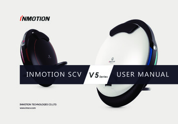
PartBefore discarding any packing materials, check that theAdjustable Base parts are as follows:Part K (1) Mattress Retainer & Hardware(4) 2” Screw in Legs(4) 4” Screw in Legs(1) Hand Control (1) Owners Manual (1) Registration Form (1) Optional Accessory Order Form(1) Mattress Retainer(2) Flat Head Screws(2) Capture Washers2"6"4"Screw in Adjustable LegsOwners ManualC10B24F80/90S86/G941-855-690-6699 toll free number for serviceG9605
INSTALLATION GUIDEIt is recommended that 2 Adults perform theinstallation process for safety reasonsSTEP 1STEP 2STEP 3STEP 4Cut straps on carton and discard all packing materials not to beused.Lift top carton from box and remove all parts. Identify all partsneeded for usage. Keep Manual and all paperwork in a safestorage and record serial number and date of purchase.Keep the underside of the Adjustable Base frame facing up andattach legs. Bases are delivered with an assortment of leg optionheights to allow you to choose your best height adjustment. Ifneeded, additional sizes are provided on the Optional AccessoryOrder Form.Extend power cord from the packaging. Once all legs/casters areattached and tightened securely, slowly turn and lift base overso top of base is facing up. Do not roll base over as this maydamage the legs. DO NOT DROP BASE.STEP 5Remove any plastic wrapping and discard. Keep out of reach ofchildren and pets.STEP 6Plug base into a working, grounded electrical outlet. It isrecommended that the base be plugged into an electrical surgeprotector (not provided or included with base).STEP 7For Wired Hand Controls, uncoil cord and test base using allfunctions on handset that is attached. If base does not operate consult the trouble shooting guide in this manual.For Wireless Hand Controls, install batteries where applicable.The base will need approximately 20 seconds before being able toreceive a signal from Hand Set once it is plugged in. See remotecontrol handset instructions.6American Adjustables
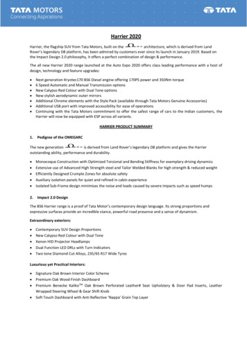
INSTALLATION GUIDESTEP 8Return base to a flat position. Identify Capture Washer and PhillipsHead Screw on foot section of base already installed. Usesupplied hardware with Mattress Retainer bracket (1 per side).Loosen Phillips Head Screw “counter-clock-wise” only a fewturns (do not remove) high enough to allow Mattress Retainer to fitunderneath the Capture Washer as shown. Once both sides are inposition, tighten both sides to hold mattress retainer in place.Mattress RetainerCapture WasherSTEP 9Phillips Head ScrewIf Headboard is to be attached using Headboard Brackets (optional),locate Headboard Brackets and follow instructions included in carton.***Should your base ever need service, please contact customer service. A servicetechnician will expertly make necessary repairs. Service technicians are notresponsible for installing or removing headboards, footboards, or side rails tocomplete service. Service technicians are not responsible for moving furniture or anyitems required to preform routine maintenance. Testing functions, changing batteries,and checking for Power to the Adjustable Base are considered non- warranty issuesand are expected to be completed by the customer. Removing and replacing Sheetsand Covers are not the responsibility of the technician.1-855-690-6699 toll free number for service7
ADDING OR PROGRAMMINGA WIRELESS REMOTE CONTROLYour Wireless Remote Control included with your Adjustable Base will alreadybe set (programmed) to your base. No Programming should be needed. Thefollowing instructions are included for your convenience should your remoteneed reprogramming or for adding an additional remote control at another time.Your Adjustable Base will already be set/programmed to the wireless Remote Controldelivered with it (1 per Adjustable Base).STEP 1The back and leg portion of the base must be in the fully down/flat position beforecontinuing and activating the learning mode.STEP 2Push and continue to hold the "reset" button on the lift motor with a pencil, golftee, or similar object and keep the button pressed in. (This is the learn mode see picture below)While holding the "reset" button IN, press head up button on the WirelessRemote Hand Control for 3 seconds. Release reset button on motor and thenrelease button on remote.STEP 3STEP 4If programming two remotes to one base, continue to hold in the reset buttonand push head up button on the second remote for 3 seconds. Release "reset"button on motor - then release button on remote.After activating the first or second wireless hand control, the "reset" button onmotor MUST be released before you release the button on your remote.Your wireless hand control should now activate the base.Test Functions.**Note- be aware that this equipment uses 433MHz. No noise signal fromother RF equipment can activate the system, but might disturb, interfere, orprevent it from running depending on the strength of the noise signal while inuse.Reset buttonRESET8American Adjustables
HEADBOARD BRACKET INSTALLATION(Note: This is an Optional Accessory which can be purchasedseparately. Please refer to the Optional Accessory pageprovided with your Owners Manual)STEP 1A. Open box and identify all parts of packaging before discardingany materials or items.B. Verify that all parts match before going further- if parts aremissing do not return- call customer service on paperwork provided.STEP 2Identify Parts included in package as follows:Tools Needed-(not supplied): 10mm Socket and Ratchet, 10mmWrench (2) Mounting Plates (Left or Right Side) (2) Mounting Bars (Left 0r Right Side) (4) 3 1/2” -1/4” x 20 bolts- (optionalfor mounting after completion- to yourheadboard)(16) 1/4” x 20 Hex Nuts (16) 1/4” Locking Washers (4 pictured) (4) 2 1/2” -1/4” x 20 bolts (16) 1/4” Flat Washers (8) 1 1/2” - 1/4” x 20 bolts (4 pictured)(2) Mounting Plates(8) 1 4” – Flat Washers(2) Mounting Bars(8) 1 1 2” – 1 4” x 20 bolts(4 pictured)(8) 1 4” x 20 Hex Nuts(4) 2 1 2” – 1 4” x 20 bolts(4)- 3 1 2” – 1 4” x 20 bolts(8) 1 4” – Locking Washers(4 pictured)1-855-690-6699 toll free number for serviceOwners Manual FINAL NO BLEED.indd 99Revised 9/17/2015
HEADBOARD BRACKET INSTALLATIONTips before getting startedSTEP 1STEP 2 Remove Mattress before installation Use your Hand Control to raise the “Back Section” of theAdjustable Base to “full up” The Frame Mounting Bars are installed “above” or “on top” ofthe Head Cross Support. They are to face outward-away fromcenter of the base (except for Split Queen & Cal King sizeswhich should be facing inward- towards the center of thebase ) There are many styles of Headboards. It is recommended toHand Tighten all hex nuts to be able to line up correctly all partsbefore completion- then securely tighten once everything iscorrectly in place The Mounting Plates are Right and Left -sided. They can bereversed facing either up or down to accommodate installationdepending on matching holes for your headboardParts Needed - (2) Mounting Bars, for each Mounting Bar- (2) 2 1 2”– 1 4” x 20 bolts, (2) 1 4” Hex Nuts, (2) Lock and (2) Flat Washers.Use 10mm Socket and Ratchet and 10mm Wrench (not supplied)(4) 2 1/2” - 1/4” x 20Bolts(2) Mounting Bars(4) Flat Washers(4) 1/4” Hex Nuts(4) Lock WashersPlace Mounting Bar “above” or “on top” of the two holes providedin the Head Cross Support at the head of the base. The MountingBar should face outward. (Note: For Split Queen and Cal King theseshould face inward). To attach, use (1) Flat washer and (1) 2 1 2”1/4”x20 bolt and thread from Top of Mounting Bar through frame.Underneath the cross bar, match with (1) 1 4” locking washer and(1) 1 4” hex nut and hand tighten. Use the same instructions for theopposite side with matching parts.10American Adjustables
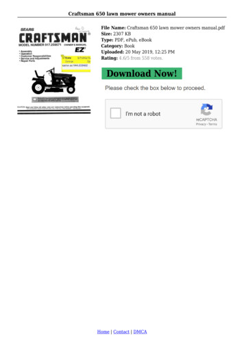
HEADBOARD BRACKET INSTALLATIONSTEP 3Parts Needed - (2) Mounting Plates, for each Mounting Plate- (2)1 1 2” – 1 4” x 20 bolts, (2)- 1 4” Hex Nuts, (2)-Lock and (2)-FlatWashers. Use 10mm Socket and Ratchet, 10mm Wrench (notsupplied)(4) 2 1/2” - 1/4” x 20 Bolts(2) Mounting Bars(4) 1/4” Hex Nuts(4) Lock Washers(4) Flat WashersMounting Plates are designed to fit either up or down depending onyour headboard for convenience and a better fit. Notice that thereis a “left” and “right” hand piece. Line up the correct piece beforeattaching to existing holes (on the Mounting Bar) to match yourheadboard and place against Mounting Bar so the fit is flush againstit. Slide the Mounting Plate back and forth to line up to Headboardinstallation. To attach, use (1) Flat washer and (1) 1 1 2”- 1 4” x20bolt and thread from back of Mounting Plate. On inside, match with(1) 1 4” Locking Washer and (1) 1 4” Hex Nut and hand tighten. Usethe same instructions for the opposite side with matching parts.Align Mounting Plate with headboard and attach to headboard.[(4) 3 1 2 - 1 4” x 20 bolts are added for your convenience.)]Once attached to Headboard, secure all (8) Hex Nuts tight using10mm Socket and Ratchet and 10mmWrench. Secure a tight fitand complete attaching headboard. Once all is Tightened lowerBack section and install Mattress. Make any necessaryadjustments for Mattress and Adjustable base to clearHeadboard at this time.Model's C10, B20/24, S80/84-mount toinside 2 holes on top of frame-non"EasyReach" frame shownModel's G90/94, P98- Note: Mount to "inserts"on outside top of frame- "EasyReach" frameshown1-855-690-6699 toll free number for service11
TROUBLESHOOTINGTroubleshooting for Wired Hand ControlProblemWired Hand ControlWill Not Operate theAdjustable BaseBack and/ or Leg WillNot RaiseSolution Verify that the Adjustable Base is plugged into a working, groundedelectrical outlet. Test outlet by plugging in another small appliance tocheck power. A grounded electrical surge protector is recommendedbut is not supplied with this Adjustable Base. Check light switch onwall Verify that the hand control is securely plugged into the port on themotor and it is secure Verify that the Adjustable Base power cord is plugged into the motor Check the circuit breaker to be sure it has not been tripped Unplug power cord from electrical outlet or surge protector and wait45 seconds and try again Check to make sure that no obstruction is limiting the sections fromlifting or lowering, if so remove obstruction Back section may be too close to Wall or Headboard which will stopmovement. Re-adjust position of base distance from wall or headboardTroubleshooting for Wireless Hand ControlProblemWireless HandControl Will NotOperate theAdjustable BaseBack and/ or Leg WillNot Raise12Solution Verify that the Adjustable Base is plugged into a working, groundedelectrical outlet. Test outlet by plugging in another small appliance tocheck power. A grounded electrical surge protector is recommendedbut is not supplied with this Adjustable Base. Check light switch onwall Verify that the Adjustable Base power cord is plugged into the motor Verify that the remote control illuminates. Test batteries where applicable. Check the circuit breaker to be sure it has not been tripped Unplug power cord from electrical outlet or surge protector and wait45 seconds and try again Check to make sure that no obstruction is limiting the sections fromlifting or lowering, if so remove obstruction Back section may be too close to Wall or Headboard which will stopmovement. Readjust position of base distance from wall or headboardAmerican Adjustables
TROUBLESHOOTINGExcessive Massage or Motor Noise If Adjustable Base is located on a hard surface floor, place rubber cups (notsupplied/optional) or carpet squares under each leg or Caster (not supplied) Check to be sure all hardware was removed upon delivery and set up. Checkto be sure Headboard Brackets (not supplied/optional) are tight and installedproperly. Make sure this is tightened firmly. Check existing frame for noise Raise the Back and Leg sections slightly using the hand control when massagemotors are on Verify that the Adjustable Base is not touching the Wall or HeadboardCommon Instructions for Wired and Wireless Hand Control Use1-855-690-6699 toll free number for service13
OPTIONAL ACCESSORY ITEMSACCESSORY DESCRIPTIONITEM #2” SCREW IN LEG - SET(4)AC- HS-2INLEG-4PACK4” SCREW IN LEG- SET(4)AC-HS-4INLEG-4PACK6" SCREW IN LEG- SET (4)AC-HS-6INLEG-4PACKHD 2” SCREW INLOCKING CASTER - Set (4)AC-2INCASTER-4PACKNON-SLIP CASTER CUPAC-CASTER CUPS LARGE2" SCREW in NYLON GLIDE- SET(4)AC-2INGLIDE-4PACKUSB /AC Power Supply20-FF-PWRSTRIPDUAL BASE ATTACHMENT KITAC-DUALBASE ATCH SETHEADBOARD BRACKET KITAC-HS980074-HB-BRKT***SYNC KIT B20 1PCAC-PARALELL-B20KIT***SELECT MODELSSYNC KIT- B24, S84, G94,P98 - 1 PCAC-PARALELL-RE-TD320-LN-WIRED-HJH1GWired Hand Control C10Wireless B24F20-LN-RF-24F-RemoteWIRED 80/90 HAND CONTROL20-LN-WIRED-HB12WLWIRELESS HAND CONTROL S86/G9420-LN-RF-94 REMOTEWIRELESS HAND CONTROL 96AB stables.comIMAGE
LIMITED WARRANTYIn the explanation of this warranty: “Adjustable Base” means the Adjustable Base foundation ONLY, sold by American Adjustables or“American Adjustables”. The “Adjustable Base” does not include the mattress. The “Purchaser” and “You”both mean the Consumer/Customer who is the original purchaser of this Adjustable Base. This warranty is not transferable. The “Warranty Starting Date” meanseither the date “You” purchased a new and unused “American Adjustables” Adjustable Base or the date of manufacture of this AdjustableBase verified by the Law Tag/Serial Number or a Valid Store retail receipt. If “You” purchased an Adjustable Base that has been used asa floor or display model, refer to the explanation below. All warranty claims require notice from You to be given to “AmericanAdjustables”. The time/date period of your initial contact call may be recorded, and will act as an initial opportunity to satisfy warrantybelow.Period of Warranty as Purchased New & Unused: 3/5/20 Years- Limited WarrantyFrom “Warranty Starting Date” as set out in above description: Year 1-3 American Adjustables will repair or replace any defective adjustable base part, and “American Adjustables” will pay ALLauthorized labor and transportation costs associated with the repair or replacement of any parts found to be defective in that 1stcalendar year. Year’s 4 & 5- American Adjustables will replace any part found to be defective at no charge. You/Customer/Consumer areresponsible to pay all service/labor and transportation/shipping costs related to the costs of receiving and installation of the newpart.Year 6-20- Mechanism parts of the Adjustable Base will be covered under a pro-rated formula. Starting on the 6th Year and endingat the end of the 20th Year, You/Customer are responsible to pay all service/labor and transportation costs related to the costs ofreceiving and installation of the new part. The cost will be figured on the then replacement cost of the part, divided by 1/15th times(x) the number of year in the 6-20th year. Example- If you/Customer are replacing a part in the 10th year after purchase, yourcharge for the said part (@ 100) would be- 100 divided by 1/15 14.29 x 5 (number of years used out of warranty 10-5 5),your charge for said part pro-rated would be 6.67 x 5 33.33. (plus shipping and labor)For Floor/ Display Model Adjustable Base: Base will be warranted as above, taking the date of manufacture on the Law Tag on the Adjustable Base or Serial NumberManufactured as the starting date/purchase date of warranty coverage.EXCLUSIONS:This warranty does not apply: to costs for unnecessary service calls, including costs for in-home service calls for the purpose of educating You about the adjustablebase or finding a satisfactory power connection to any damage caused by You if there has been any repair or replacement of adjustable base parts by an unauthorized person if the adjustable base has been mishandled (whether in transit or by other means), subjected to physical or electrical abuse or misuse to damage to mattress or mattresses to water or any liquids to any bodily fluids will void all warranty to fabric to cables, electrical cords or any items not supplied by American Adjustables in original box (contact the dealer for warrantyinformation on these items if there has been any modification of the adjustable base if the recommended weight restriction is not followed (refer to the advisory section of the Owner’s Manual) if you sell, give or transfer the base to another personThe decision to repair or to replace defective parts under this warranty shall be made, or cause to be made, by American Adjustables atits option and in its sole discretion.A repair initiation shall be the responsibility of the Purchaser. This limited warranty does not include reimbursement for inconvenience,removal, installation, setup time, loss of use, shipping, or any other costs or expenses. American Adjustables and its service technicianswill not be responsible for moving furniture or any other items not attached to the adjustable base in order to perform service onthe adjustable base. It is the sole responsibility of You to provide adequate space and accessibility to the adjustable base. It is yourresponsibility to remove sheets/covers and all linens before service is performed. In the event that the technician is unable to performservice due to lack of accessibility, the service call will be billed to You and the service will have to be rescheduled.American Adjustables2618 Brick Church PikeNashville TN, 37207855-690-66991-855-690-6699 toll free number for service15
Notes:If you experience any trouble with your Adjustable Base please consult the TroubleShooting Guide provided in the Owners Manual. If problems persist, Please call:CUSTOMER TOLL FREE NUMBER1-855-690-6699American Adjustables2618 Brick Church PikeNashville TN, 37207
STEP 8 . STEP 9 . Return base to a flat position. Identify Capture Washer and Phillips Head Screw onfoot section of base already installed. Use supplied hardware with Mattress Retainer bracket (1 per side).