Transcription
FCC ID: NCT048L10 IC: 2802A-048L10CE 0678WARRANTYINMOTION Controls, Inc. guarantees that this product meets its publishedspecification at the time of shipment from the factory. Under proper installation, itshould work as expected. However, INMOTION Controls, Inc. does not guaranteethat operation of the 310 Series Radio Control System is error-free or withoutinterruption.This equipment is warranted against defects in materials and workmanship for aperiod of one year from the date of shipment. During the warranty period,INMOTION Controls, Inc. is responsible for necessary repairs, as long as theproduct can be proved to be defective.For warranty service or repair, this product must be returned to our factory.Customer is responsible for shipping charges to INMOTION Controls, Inc., whileINMOTION Controls, Inc. will pay return shipping charges.This warranty does NOT include consumable parts, such as joystick, batteries,fuses, buttons, and relays or damage from normal wear and tear. Furthermore, thiswarranty does NOT cover defects caused by misuse, neglect, accident, failure tofollow instructions, improper installation, improper or insufficient maintenance,unauthorized modification, unsuitable operating environment, improper operation,ignorance of environmental specifications, improper software/interfacing, fire, oracts of God. No other warranty is expressed or implied, except for the abovementioned The remedies provided herein are the buyers’ sole and exclusiveremedies. INMOTION Controls, Inc. shall not be liable for any direct/indirect,special, incidental or consequential damages.1
OPERATING PRECAUTIONSATTENTION Due to the complex nature of the equipment, it is necessaryto read the entire manual before installation. Never dismantle equipment by any unauthorized personnel,or equipment may be damaged. This Manual is for reference only; please call your distributorif further assistance is required. This equipment has been strictly tested for quality beforedelivery from our factory. However, it must not be usedin extremely dangerous situations, or where damage mayresult. After operating, please shut off main power in Crane and thepower to Receiver. Transmitter should be placed safely when not in use to avoidaccidental pressing of buttons. The Crane should be equipped with main power Relay, LimitSwitch and other required safety devices. The GND (ground) of Receiver must be connected with metalpart of Crane, or electrical shock will occur. Do not use this device during electrical storm, or highelectrical interference conditions. Ensure Transmitter batteries are in good condition and powerfor Receiver is normal. Installation and maintenance should be done only while theCrane’s main power and Receiver’s power are OFF, toprevent electrical shock. Contents of the Manual may be amended by themanufacturer without notice.2
PRECAUTIONS After Operating Series 310, please press EMO (Emergency Off)mushroom and turn the keyswich to the “Off” to shut off mainpower in the Crane & Receiver. Stop operating when slow-response occurs due to insufficientTransmitter power, beyond the remote control range, or severeinterference. Remove the batteries when the equipment won’t be used for a longperiod. Operators must be in good health and have good judgment in regardsto safety. Remote Control operator must have adequate training and relatedlicense to avoid danger. Series 310 Transmitter is durable and weather-resistant, but careshould be taken not to subject it to severe impact or pressure. Series 310 is suitable for use in diverse industrial environments, andadequate operating and maintenance will extend system’s life. Check EMO mushroom and the other security functions of Series310 system before daily operation. Press EMO mushroom when malfunctions or abnormal conditionsoccur. Operator must be familiar with the following Emergency Proceduresbefore operating.3
EMERGENCY PROCEDURESIn case of emergency, please follow the steps below and ask the distributorfor service immediately. Press EMO mushroom Remove the batteries Shut off the main power of the Crane and discontinue theoperationContact the distributor to find out possible causes.4
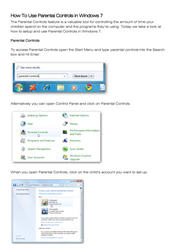
STANDARD ACCESSORIESA standard and full set of Series 310 consists of:(1) Transmitter, 2 units(2) Receiver, 1 unitNote:Inmotion Series 310 Shown. Models vary depending on options.5
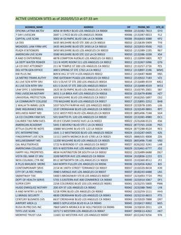
OPERATIONTRANSMITTER CONFIGURATIONNote:Inmotion Series 310 Shown. Models vary depending on options.6
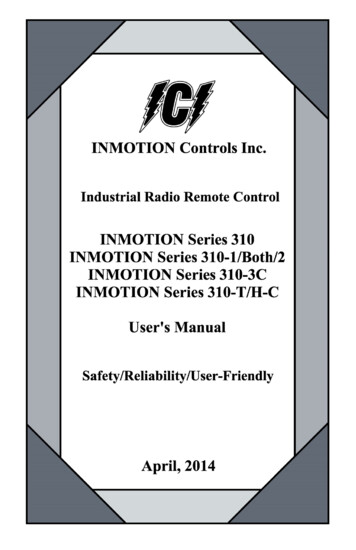
RECEIVER CONFIGURATIONNote:Inmotion Series 310 Shown. Models vary depending on options.7
GENERAL OPERATION Turn on the main power switch of the equipment (Crane). Install 2 AA batteries in the battery box in the Transmitter.Make sure the polarity is correct. Attach Transmitter battery door with screws. Insert security key in the “OFF’ position. Turn the keyswitch clockwise to the “ON” position, then continueto turn it to the “START” position to power-on.Note: LED indicator will flash red if proper procedures arenot followed. Operate Transmitter by pressing each pushbutton. After operation, perform the following procedures in sequence:(1) Press EMO mushroom(2) Turn the keyswitch to the “OFF” position.(3) Remove key and keep the transmitter in a safe place.(4) Switch main power off to the equipment (Crane).(5) Remove batteries if not used for a long period of time.Note: Transmitter has power indicating functions with LEDdisplay. “Green Color” – The LED will flash green when batterypower is sufficient.“Red Color” – The LED will flash red when the power islow. The operating distance will become shorter andintermittent when the batteries are low. Replace with new batteries when battery poweris low.! DO NOT USE RECHARGEABLE BATTERIES !8
RECEIVER VOLTAGE SELECTIONThere are two types of power voltages (DC and AC) availablefor the Series 310.1) DC Type:Input Voltage: 12 24 VDCRelay Contact: 10A-36 VDC2) AC Type:Three different AC transformers:48/110/220V, 48/220/380V, 110/220/380V.Please disconnect the Receiver’s power, select the propervoltage, and plug in the connector. See picture below.Note: Standard Systems are 48/110/220 VAC. If any others arerequired, please specify when ordering.9
CHANGING THE FREQUENCYIt is easy to change the frequency of the Series 310 simply byreplacing corresponding frequency crystals in both theTransmitter and the Receiver.Instructions:1. Pry up the crystal with a flathead screwdriver.2. Remove the crystal from the system.3. Use needle nose pliers to straighten both pins of thenew crystal.4. Insert the new crystal vertically into the PC board.5. Press the new crystal down into the socket.ATTENTION :The Transmitter frequency will be different from the Receiverfrequency. For example, the transmitter crystals are labeledT01 thru T40 and receiver crystals are labeled R01 thru R40.FREQUENCY CHARTCh12345678910Freq. 81920Freq. 82930Freq. 83940Freq. 0319.6625319.9300320.1975320.465010
BATTERIESTwo AA size alkaline batteries are required for the Transmitter.The LED will flash green when the battery power is sufficient.The LED will flash red when the battery power is low. The operating distance will become shorter and intermittentwhen the battery is low. Replace with new battery when battery power is low.! DO NOT USE RECHARGEABLE BATTERIES !11
INSTALLATION NOTES12
13
14
INMOTION Controls, Inc. guarantees that this product meets its published specification at the time of shipment from the factory. Under proper installation, it should work as expected. However, INMOTION Controls, Inc. does not guarantee that operation of the 310 Series Radio Control System is error-free or without interruption.