Transcription
Installation and Maintenance ManualDestiny Indoor Air HandlerIM 782-7Group: Applied AirPart Number: IM 782Date: March 2012Sizes 002 through 030 2013 Daikin Applied
ContentsIntroduction . . . . . . . . . . . . . . . . . . . . . . . . . . . . . . . 3General Information . . . . . . . . . . . . . . . . . . . . . . . 3Smoke Control and Management Systems. . . 3Receiving and Handling . . . . . . . . . . . . . . . . . 4Storing the Unit . . . . . . . . . . . . . . . . . . . . . . . . 4Installation Guidelines . . . . . . . . . . . . . . . . . . . . . . 5Attaching the Mixing Box . . . . . . . . . . . . . . . . . . . 5Service Clearances . . . . . . . . . . . . . . . . . . . . . . . 6Rigging . . . . . . . . . . . . . . . . . . . . . . . . . . . . . . . . . 7Unit Leveling . . . . . . . . . . . . . . . . . . . . . . . . . . . . 7Panels and Doors. . . . . . . . . . . . . . . . . . . . . . . . . 8Panel Removal . . . . . . . . . . . . . . . . . . . . . . . . 8Actuators . . . . . . . . . . . . . . . . . . . . . . . . . . . . . . . 8Installing Damper Actuator . . . . . . . . . . . . . . . 9Reversing the Coil Handing . . . . . . . . . . . . . . . . 10Reversing the Belt Drive Package . . . . . . . . . . . 12Hanging the Unit from a Ceiling . . . . . . . . . . . . . 12Piping and Coils . . . . . . . . . . . . . . . . . . . . . . . . . 13Water Cooling Coils . . . . . . . . . . . . . . . . . . . 13Direct Expansion Coils . . . . . . . . . . . . . . . . . 13Steam Coils (provided as Specials only). . . . 13Water Heating Coils . . . . . . . . . . . . . . . . . . . 14Drain Pan Traps . . . . . . . . . . . . . . . . . . . . . . . . . 15Internal Isolation Assembly Adjustment . . . . . . . 15Before Operating the Unit . . . . . . . . . . . . . . . 15Spring Mount Adjustments—Twin Fan Units 15Electric Heat Section (Optional) . . . . . . . . . . . . . 16Open Coil Duct Heater . . . . . . . . . . . . . . . . . 16Single Point Power . . . . . . . . . . . . . . . . . . . . 16Quality Control . . . . . . . . . . . . . . . . . . . . . . . 16Electric Heat kW Options . . . . . . . . . . . . . . . 17Heater Amps . . . . . . . . . . . . . . . . . . . . . . . . . 17Electric Heat Safety. . . . . . . . . . . . . . . . . . . . 18Minimum Air Velocity. . . . . . . . . . . . . . . . . . . 19Electric Heat Operation . . . . . . . . . . . . . . . . . 20Field Power Wiring . . . . . . . . . . . . . . . . . . . . 20Supply Power Wiring. . . . . . . . . . . . . . . . . . . 20Electrical Installation . . . . . . . . . . . . . . . . . . . 20Variable Frequency Drive (VFD) - Optional . 21Starters and Disconnect - Optional. . . . . . . .Wiring Diagrams . . . . . . . . . . . . . . . . . . . . . . . . . .Electric Heat Diagrams . . . . . . . . . . . . . . . . . . .Disconnect-Only Diagrams . . . . . . . . . . . . . . . .VFD Diagrams . . . . . . . . . . . . . . . . . . . . . . . . . .Physical Data. . . . . . . . . . . . . . . . . . . . . . . . . . . . .Component and Section Weights . . . . . . . . . . .Fan Data . . . . . . . . . . . . . . . . . . . . . . . . . . . . . .Filter Data . . . . . . . . . . . . . . . . . . . . . . . . . . . . .Coil Data . . . . . . . . . . . . . . . . . . . . . . . . . . . . . .Drain Pan Data . . . . . . . . . . . . . . . . . . . . . . . . .Electric Heat Data . . . . . . . . . . . . . . . . . . . . . . .Fan Curves . . . . . . . . . . . . . . . . . . . . . . . . . . . . . .Dimensional Data . . . . . . . . . . . . . . . . . . . . . . . . .Cabinet Dimensions—Horizontal. . . . . . . . . . . .Cabinet Dimensions—Vertical . . . . . . . . . . . . . .Mixing Box Dimensions . . . . . . . . . . . . . . . . . . .Electric Heat Dimensions—Left/Right Oriented.Control Box Dimensions . . . . . . . . . . . . . . . . . .Operation Guidelines . . . . . . . . . . . . . . . . . . . . . .Startup Checks . . . . . . . . . . . . . . . . . . . . . . . . .Before Starting the Unit . . . . . . . . . . . . . . . .Operating Limits . . . . . . . . . . . . . . . . . . . . . .Fan Vibration Levels. . . . . . . . . . . . . . . . . . .Service and Maintenance . . . . . . . . . . . . . . . . . . .Periodic Service and Maintenance . . . . . . . . . .Ball Bearing Lubrication . . . . . . . . . . . . . . . .Fan Drive Adjustments . . . . . . . . . . . . . . . . .Fan Drive Belt Adjustment . . . . . . . . . . . . . .Coil Maintenance . . . . . . . . . . . . . . . . . . . . .Component Removal and Replacement. . . .Warranty . . . . . . . . . . . . . . . . . . . . . . . . . . . . . . . .Warranty Details . . . . . . . . . . . . . . . . . . . . . . . .Warranty Return Material Procedure . . . . . .Replacement Parts . . . . . . . . . . . . . . . . . . . .Destiny Equipment Warranty Registration FormQuality Assurance Survey Report . . . . . . . . . . 8484848525353545454545557
IntroductionIntroductionGeneral InformationWARNINGWARNINGImproper installation or maintenance can cause equipmentdamage or personal injury.Installation and maintenance must be performed by qualifiedpersonnel familiar with applicable codes and regulations, andexperienced with this type of equipment.Fan motor requires overload protection.Failure to provide motor overload protection can result in fire,property damage, electric shock, personal injury or death.Connect motor to an overload protective device rated incompliance with local electric codes.AVERTISSEMENTAVERTISSEMENTUne installation ou un entretien inadéquats peutendommager l’équipement ou entraîner des blessurespersonnelles. L’installation et l’entretien doivent êtreexécutés par un personnel qualifié, familier avec les codes etrèglements applicables et possédant de l’expérience avec cetype d’équipement.Risques d’incendie. À défaut d’installer un sectionneur àfusible à action rapide de type J, cela peut entraîner desdommages à la propriété, des blessures ou la mort.Un sectionneur à fusible à action rapide de type J doit êtreinstallé avant le variateur de fréquenceSmoke Control and Management SystemsCAUTIONSharp edges and coil surfaces can cause personal injury.Avoid contact with them.ATTENTIONLes bords tranchants et les surfaces des bobines sont unrisque de blessure. Ne les touchez pas.CAUTIONDestiny units are not designed to be weather resistant; DONOT install outdoors.ATTENTIONLes Unités Destiny ne sont pas à l’épreuve des intempéries;NE PAS les installer à l’extérieur.WARNINGImproper grounding may result in severe injury or death.Check grounding nut tightness before connecting power to theexternal junction box.AVERTISSEMENTUne mise à la terre défaillante peut causer des blessuresgraves ou la mort. Vérifiez l’étanchéité des vis de mise à terreavant d’alimenter la boite de jonction externe.Daikin IM 782-7The system design and installation must follow acceptedindustry practice, such as described in the ASHRAEHandbook, the National Electric Code, and other applicablestandards. The installation of this equipment must be inaccordance with regulations of authorities having jurisdictionand all applicable codes. It is the responsibility of the installerto determine and follow the applicable codes.WARNINGImproper smoke or fume air handling can result in severepersonal injury or death.A registered professional engineer must design and approvethe air conditioner and air handler application to make suresmoke and fume control meet local fire codes and NFPArequirements for the specific building application.Due to the wide variation in building design and ambientoperating conditions into which our products can be applied,we do not represent or warrant that our products will be fit andsufficient for smoke and fume control and managementpurposes. The owner and building designer must consult aregistered professional engineer to satisfy themselves in thisregard.AVERTISSEMENTUn traitement inadéquat de l’air contenant de la fumée peutentraîner des blessures personnelles ou même la mort.Un ingénieur professionnel doit faire la conception etapprouver l’unité de traitement d’air et son application pours’assurer que le contrôle de la fumée rencontre les codesd’incendies locaux et les normes NFPA pour l’applicationspécifique du bâtiment.Dû à la grande diversité de conceptions des édifices ainsi quedes conditions d’opération ambiantes dans lesquelles nosproduits peuvent être appliqués, nous n’avançons ni ne garantissons que nos produits seront adéquats et efficaces quant aucontrôle de la fumée. Le propriétaire et le concepteur dubâtiment doivent consulter un ingénieur professionnel à cetégard3
IntroductionReceiving and Handling1 Carefully check items against the bills of lading to verifyall crates and cartons were received. Carefully inspect allunits for damage when received. Report visible andconcealed damage immediately to the carrier and a file aclaim for damage.2 Destiny air handler units are thoroughly inspected beforeleaving the factory. Install units carefully to preventdamage.3 Leave enough space around the unit for propermaintenance, filter removal, lubrication, belt adjustment,and removal of coils, if necessary (refer to Figure 2 forservice clearances).4 Use flexible connections on the inlet and outlet ductconnections of the unit.5 For 002 - 010 sized ceiling hung units, spring isolation ofthe cabinet is recommended.46 All fans are dynamically balanced before leaving thefactory. Carefully inspect fans for rough handling thatcan cause misalignment or a damaged shaft.7 Adequately pitch and trap drain line from drain panconnection.Storing the UnitStore unit on a level surface. If air handling units are to bestored for any period of time, it is important to rotate the fanwheel (quarterly, as a minimum) to prevent permanentdistortion of drive components. Keep the fan bearingslubricated. Grease may settle in the lower part of the bearing,which may lead to oxidation on the upper portion of thebearing surface.Store units indoors in a clean, dry environment on a levelsurface. Moisture, debris, and minerals can cause permanentdamage to the cabinet and components. Do not allowcoverings to trap moisture on the galvanized surface.Daikin IM 782-7
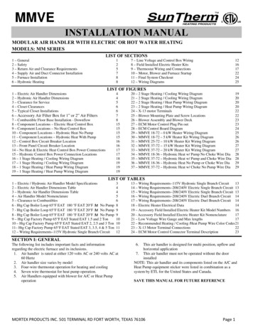
Installation GuidelinesInstallation GuidelinesAttaching the Mixing BoxMixing boxes ship with Destiny units as a field-installedoption. Attach the mixing box to the intake end of the airhandler using cleats included with the mixing box section.Install the cleats into the interior mounting frames, with thehardware included as shown in Figure 1.Figure 1: Mixing Box InstallationCleat locationsCleat locations(sizes 015 and above)CleatinstallationDaikin IM 782-75
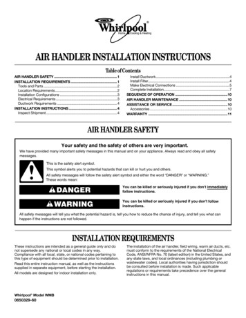
Installation GuidelinesService ClearancesLeave adequate space around the unit for piping, coils, anddrains. Always have access to at least one side of the unit forregular service and maintenance. See Figure 2 for servicingspace requirements. Routine maintenance examples includefilter replacement, drain pan inspection and cleaning, fanbearing lubrication, and belt adjustment. Provide sufficientspace on the drive side of the fan and the connection side ofthe coil for shaft and coil removal, if necessary (refer to the“Coil Data” section in Catalog 580 for information about coilsizes). Both the fan drive and coil can be field modified toright or left hand to accommodate clearance restrictions. SeeReversing the Coil Handing‚ page 10 and Reversing the BeltDrive Package‚ page 12.For routine maintenance, remove panels on either side of theunit. See Panel Removal‚ page 8. Optional service doors areavailable for the fan and filter sections. Allow sufficient spacefor service door(s) to swing completely open, or to meet theclearance requirement of the section it accesses, whichever isgreater. Service doors are not interchangeable with accesspanels on the opposite side of the unit. Determine clearancesbefore specifying doors.Have at least 54" of clearance in front of electrical powerdevices (starters, VFDs, disconnect switches, and combinationdevices). Electrical power devices that are mounted on the sideof the unit typically are 6" deep (12" maximum (see Figure 2,page 6).Figure 2: Servicing Space RequirementsVertical uni tTo p viewWidthWidthHeight30.00”Width offan sectionHorizontal unitWidth ofCoil sectionElectric power clearanceHeight54"Width6For Bottom Filter Access OnlyProvide 30" Vertical Clearance forFilter Removal12" (maximum)Daikin IM 782-7
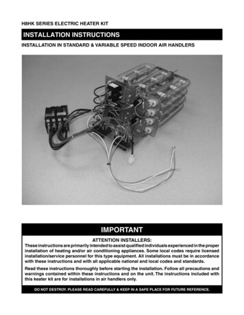
Installation GuidelinesRiggingUnit LevelingRig units using straps or a sling. Fasten strapping under theskid that ships with the section. If a field-installed mixing boxis attached, adjust to balance the unit properly.Place the equipment on a flat and level surface (or verify thatunit is level when hanging from the ceiling). Where the surfaceirregularities allow the equipment to distort, shim the base ofthe unit to a straight line. Distorted units can cause misfit orbinding of the doors and panels and improper draining of drainpans.To avoid damage to the unit cabinetry, use spreader bars.Position spreader bars to keep cables from rubbing the frame,connections, or panels. Before hoisting into position, test liftfor stability and balance. Avoid twisting or uneven lifting ofthe unit.Figure 4: Leveling the UnitHorizontal unitFigure 3: Rigged Unit on SkidsHorizontal unitVertical unitVertical unitDaikin IM 782-77
Installation GuidelinesPanels and DoorsFigure 6: Fan Section DoorsDANGERHazardous moving parts, high static pressure, and/or highvoltage. Can cause severe injury or death.Disconnect and lock ALL electric power off before entering orservicing unit. Unit may employ multiple power supplies and/orremote disconnects.Secure drive sheaves to prevent motors and fan from freewheeling.When leaving the unit, use screw or door handle lockingmechanism provided to secure access panel closed andprevent unintentional entry.DANGERPieces mobiles dangereuses, haute pression statique et/oude hautes tensions. Risques de blessures graves, voiremortelles.Débranchez et verrouillez toutes les alimentation électriquesavant de pénétrer ou d’intervenir sur cet appareil. Cet appareilpeut étre alimenté par plusieurs sources etlou parl’intermédiaire de plusieurs disjoncteurs éloignés.Attachez les disques d’entrainement afin d’éviter que lesmoteurs et le ventilateur ne tournent librement.A Ia sortie de l’appareil, fermer le panneau d’accès avec Ia visou avec le mécanisme de verrouillage de Ia poignée de portequi sont founis pour éviter toute entrée inopinée.Panel RemovalDestiny air handlers have pocket pull handles in alternatesections that allow side panels to be easily removed andhandled. To gain access through a side panel, remove thefasteners along the sides of the panel and lift the panel offusing the pocket pull handle. If the panel you are accessingdoes not have a pocket pull handle, remove an adjoining panelwith a pocket pull handle and push the panel out from insidethe unit.Figure 5: Panel RemovalActuatorsThe factory-mounted actuator has been initially adjusted in thefactory. Power and control wiring, as well as fine-tuningadjustment, is to be performed in the field.The installing contractor is responsible for the mounting of allfield-installed actuators. An actuator mounting plate isprovided on the shaft side of the damper frame toaccommodate many actuators. However, due to the number ofoptions, size variations, and arrangements available, someactuators may require alternate field provided mountinghardware. Provide proper support for the actuator to avoidexcessive stress in the cabinet, linkage, or damper shafts.Fresh air and return air dampers can be linked together anddriven from the same actuator if the dampers are the same size.If the dampers are different sizes, they must be driven byseparate actuators and controlled appropriately.A typical rotary electric actuator can handle up to 40 squarefeet of damper. For pneumatic actuators, allow 5 in.-lb. persquare foot of damper area.CAUTIONMaximum damper rotation is 70 . Maximum shaft torque is 205in.-lb. Greater rotation or torque can cause equipment damage.ATTENTIONFan Section Doors1 Use a flat head screwdriver and rotate the screw 1/4 turnas shown in Figure 6.La rotation maimale des volets est de 70 . Le couple (torque)maximum de l’arbre est de 205 in./lb. Une plus grande rotation(ou torque) peut endommager l’équipement.2 Rotate door handle 1/4 turn and open the door.8Daikin IM 782-7
Installation GuidelinesFigure 7: Factory Mounted ActuatorFor good air flow control, adjust the linkage so that the damperblades do not open beyond 70 . Opening a damper bladebeyond 70 will have little effect on unit performance.Do not “over-close” the low-leak damper blades as the bladesmay lock up if the accompanying seal goes over the center ofthe adjoining blade. Instead, close the damper blades until theedge seal just lightly contacts the adjoining blade.Installing Damper Actuator1 Turn the damper shaft until the blades are fully closed.2 Place the actuator’s universal clamp over the dampershaft (Figure 8). Make sure that the controls on theactuator cover are accessible. Place the actuator in thedesired mounting position.Figure 9: Actuator Manual Override Button and Strap4 Slide the anti-rotation strap (Figure 9) under the actuatorso it engages the actuator at the center of the actuator cutout (located on the back side). Bend the bracket asneeded to support the back side of the actuator. Securethe strap/actuator to ductwork with self-tapping screws(#8 recommended).5 Loosen the nuts on the universal clamp. Press the manualoverride button and rotate the clamp to about 5 (Figure 10) from the closed position (1/16" to 1/8"between stop and clamp).Figure 10: Actuator Universal Clamp RotationFigure 8: Actuator on Damper Shaft6 Tighten the two nuts on the universal clamp with awrench.3 Disengage the actuator gear train by pressing the manualoverride button (Figure 9) and rotate the clamp untilcentered.Daikin IM 782-79
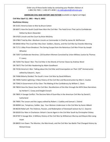
Installation GuidelinesReversing the Coil HandingDestiny coils universal-hand and coil connections can beswitched to the opposite side of the unit by rotating the coil(s)180 degrees side to side and reworking the coil section panelon the opposite side of the air handler.Note: Direct expansion (DX) coils require 180 degree rotationon the top to bottom to locate distributor tubes at theleaving face of the coil.CAUTIONSharp edges and coil surfaces can cause personal injury.Avoid contact with them.5 Rotate the coil 180 and reposition coil blockoffs to theentering air side of the coil.6 Drill holes if required and fasten the blockoffs to theentering side of the coil.7 If unit has both heating and cooling coils, position andbolt heating coil and cooling coil casings together insame arrangement in the direction of airflow as unit wasshipped from factory. Reheat coils must remain in reheatposition; do not place in preheat position. Fasten the firstcoil in the air stream to the entering side of the drain panusing the same holes provided for the coil before it wasrotated.8 Mark locations and drill holes to align with holes inupper track.ATTENTIONLes bords tranchants et les surfaces des bobines sont unrisque de blessure. Ne les touchez pas.To reverse the coil connections, follow the steps below, (alsorefer to Figure 11, page 11).1 Remove exterior panels from both sides of the coilsection. Remove screws that secure the top of the leavingcoil face to the upper track on the inside top of the unit.2 Lift drain pan condensate connection above the unitframe flange and slide drain pan, coil(s) and baffles outof unit.3 Remove screws and remove coil blockoffs.4 Remove screws holding coil to drain pan and removecoil.9 Slide the coil, blockoffs and drain pan assembly backinto unit the same way it was removed. Check theinstallation for an airtight fit. Re-install screws thatsecure the top of the leaving coil face to the upper trackon the inside top of the unit.Depending on whether the air handler was purchased fromstock or if it was manufactured for the specific job, the panelon the opposite side may or may not have predrilledconnection holes.1 If connection holes need to be drilled, determine theproper diameter in order to use the existing grommets.2 Mark connection locations on panel and drill new holesto accommodate connections and grommets.3 Plug and seal unused connection holes on opposite sidepanel with new solid grommet or other suitable material.10Daikin IM 782-7
Installation GuidelinesFigure 11: Reversing the Coil Handingscrews1 Removefrom the upper trackthat hold coil/drain panin placeholes in coil header plate7 Drillflanges, position block offsand install screws to secure to coil.Airflowdrain pan connection2 Liftup and slide coil/drain panassembly out.locations8 Markand drill holesto align with holesin upper track.screws and3 Removeremove coil blockoffs.screws4 Removeholding coil tocoil/drain pan9 Positionassembly in unit and installscrews in upper track.drain pan andremove coil.coil 180 5 Rotateand reposition inholes in coil6 Drillbottom flangedrain pan.and install screwsto secure todrain pan.All coilsexcept DXNOTE:Rotate a DX(evaporator)coil 180 TOPto BOTTOM.AirflowAirflowDistributorsmust be on theleaving air sideof the coil.Daikin IM 782-7NOTE:If a heating coilis used, positionheating coil inthe same locationas unit was shippedfrom factory. Reheatcoils must remain inreheat positon; do notplace in preheat postiion.11
Installation GuidelinesReversing the Belt Drive PackageHanging the Unit from a CeilingA motor side or “hand” is determined by looking in thedirection of air flow with the air contacting the back of thehead. The drive package on the air handler can be changed tothe other side of the blower. The motor base and motor areattached to back of the fan housing. They can be removed,rotated 180 degrees, and reattached. The fan sheave can beremoved and reinstalled on the opposite end of the shaft(Figure 12). Review Fan Drive Adjustments‚ page 48 whenreinstalling the belts.Before hanging, rig and completely assemble the unit.To reverse the drive package:1 Loosen the belt adjustment screws to relieve the drivebelt tension.2 Remove the drive belt and the blower pulley.3 Loosen the two upper bolts on the motor mounting plateand slide the motor out from the blower housing mount.4 Move the top motor mounting bolts to the bottom motormounting plate location and vice versa. Fasten securely.5 Turn the motor 180 and slide it back into the blowerhousing mount and tighten bolts.Note: Change the motor wiring so the motor rotates in theopposite direction.WARNINGDo not suspend the unit from the top. The unit top will notsupport the weight of the unit. Equipment damage and severepersonal injury can result.AVERTISSEMENTNe pas suspendre l’unité par le toit. Le dessus de l’unité nesupportera pas le poids de l’unité. Ceci pourrait entraîner desdommages à l’unité ou des blessures personnelles graves.The Destiny air handler has circular knockouts on the cornerconnections. Remove the knockouts and suspend the unit usingthreaded rods and hardware with required C-channels on bothsides as shown in Figure 13. On unit sizes 007 and larger,L-channels are required on both ends in addition toC-channels. For 002 - 010 sized ceiling hung units, springisolation of the cabinet is recommended. See Figure 13.Figure 13: Ceiling Hung Installation, Horizontal Units OnlySpring Isolators1 Install the blower pulley and the belt to the other side ofthe blower housing.2 Adjust belt tension.Figure 12: Reversing the Drive PackageUpper motormountingplate bolts (2)Lower motormountingplate bolts (2)Beltadjustmentbolts (2)C-channels are required on all units.On unit sizes 007 and above, L-channelson both ends are also required.12Daikin IM 782-7
Installation GuidelinesPiping and Coils4 Use care when piping up the system, making sure allFollow applicable piping design, sizing, and installationinformation presented in ASHRAE Handbooks in the designand installation of piping. Observe all local codes and industrystandards. Do not apply undue stress at the connection to thecoil headers. Support pipe work independently of the coils.Note: Destiny cooling coils are supplied as universal-handcoils. The coils feature four water piping connectionstubs for hydronic coils and two suction line connectionsfor DX coils. The connections to be used are clearlymarked with labels. Keep other (unmarked) connectionscapped. Refer to Figure 14 and Figure 15, detailing thecorrect stubs that are to be connected to the systempiping.joints are tight and all lines are dry and free of foreignmaterial. For typical refrigerant piping, see thecondensing unit product manual.Figure 15: DX Coil ConnectionsLIQUIDCONNECTIONAIRLH FLOWAIRFLOW RHSUCTIONCONNECTIONRight HandAir Flow CoilLeft HandAir Flow CoilWater Cooling CoilsWater cooling coil guidelines are listed below. Also, refer toFigure 14.LIQUIDCONNECTION1 Water supply, water return, drain, and vent connectionsLIQUIDCONNECTIONLH AIRFLOWAIRFLOWextend through the end panel of the coil section. Allconnections are labeled on the end panel.RHSUCTIONCONNECTION2 Water supply and water return connections are coppersweat on units 002 through 010 and male NPT iron pipeon units 015 through 030.3 When installing couplings, do not apply undue stress tothe connection extending through unit panel. Use abackup pipe wrench to avoid breaking the weldbetween coil connection and header.4 Follow recommendations of the control manufacturerregarding types, sizing, and installation of controls.Figure 14: Water Cooling Coil ConnectionsRETURNAIRLH FLOWAIRFLOW RHSUPPLYLeft Hand AIr Flow CoilRight Hand AIr Flow CoilDirect Expansion CoilsDirect expansion coil connection guidelines are listed below.Also, refer to Figure 15.1 The coil distributor and suction connection extendthrough the end panel of the coil section.2 Check nozzle in distributor for proper tonnage.3 The thermostat expansion valve must be an externalequalizer tube type. Connect the equalizer tube providedon the coil (3/16" for units 002 to 010, and 1/4" for units015 to 030) to the connection on the expansion valve.Daikin IM 782-7Left HandAir Flow CoilSUCTIONCONNECTIONRight HandAir Flow CoilSteam Coils (provided as Specials only)Steam coil connection guidelines are listed below. Also, referto Figure 16, page 14.1 All steam coils are non-distributing (freeae) type. Theyare not designed to be used in 100% OA applications.2 Steam supply and steam return connections are typicallymale NPT iron pipe and are labeled on the end panel ofcoil section. Connections extend through coil section endpanel.3 When installing couplings, do not apply undue stress tothe connection extending through unit panel. Use abackup pipe wrench to avoid breaking the weld betweencoil connection and header.4 Support piping independently of coils and provideadequate piping flexibility. Stresses resulting fromexpansion of closely coupled piping can cause seriousdamage.5 Do not reduce pipe size at the coil return connection.Carry return connection size through the dirt pocket,making the reduction at the branch leading to the trap.6 Install vacuum breakers on all applications to preventretaining condensate in the coil. Connect the vacuumbreaker between the coil inlet and the return main.7 Do not drip supply mains through the coil.13
Installation Guidelines8 Do not attempt to lift condensate when using modulatingor on/off control.9 Size traps in accordance with manufacturers’recommendations. Be certain the required pressuredifferential will always be available. Do not undersize.10 Use float and thermostatic or bucket traps with lowpressure steam. On high pressure steam, use buckettraps. Use thermostatic traps only for air venting.11 Use bucket traps only with on/off control.4 Follow recommendations of the control manufacturerregarding types, sizes, and installation of controls.5 Hot water coils are not recommended for use withentering air below 40 F.6 If fresh air and return air are to be heated by a hot watercoil, take care in the design of the system to providethorough mixing before air enters the coil.Figure 17: Water Heating Coil Connections12 Locate traps at least 12 inches below the coil returnconnection.13 Do not use modulating steam valves on high pressuresystems.14 Size modulating valves properly. Do not undersize.15 Destiny steam coils are not recommended for freezingOne and Two Row Coilwith Spayed Headersconditions or entering temperatures below 35 F (1.6 C).Figure 16: Steam Coil Connections (Type SS)Figure 18: Piping ArrangementsSteam mainVacuum breaker1/2" check valveWater Heating CoilsHeating coil connection guidelines are listed below. Also, referto Figure 17 and Figure 18.1 Water supply and water return connections extendthrough the end panel of the coil section. All connectionsare labeled on the end panel.12" min.2 Water supply and water return connections are coppersweat on units 002 through 010 and male NPT iron pipeon units 015 through 030.3 When installing couplings, do not apply undue stress toReturn mainthe connection extending through unit panel. Use abackup pipe wrench to avoid breaking the weld betweencoil connection and header.14Daikin IM 782-7
Installation GuidelinesDrain Pan TrapsSpring Mount Adjustments—Twin Fan UnitsDestiny air handlers have a drain pan connection on both sidesof the unit. Drain connections can be made on either side orboth sides. Drain lines and traps should run full size from thedrain pan connection. Drain pans should have traps to allowcondensate from coils to drain freely. The trap depth anddistance between the trap outlet and the drain pan outlet shouldbe twice the static pressure in the drain pan section undernormal operation for the trap to remain sealed. Refer toFigure 19.The spring isolators under the four corners of the fan andmotor assembly have been factory adjusted while the fan wasnot running. Refer to Table 1. With the unit operating atnormal cfm and static pressure, the isolators should all be atthe same height opening. If adjustments are
2 Destiny air handler units are thoroughly inspected before leaving the factory. Install units carefully to prevent damage. 3 Leave enough space around the unit for proper maintenance, filter removal, lubrication, belt adjustment, and removal of coils, if necessary (refer to Figure 2 for