Transcription
Configuring the Airline Product SetThis chapter describes how to configure the Airline Product Set (ALPS). For a complete description ofthe ALPS commands in this chapter, refer to the “Airline Product Set Configuration Commands” chapterin the Cisco IOS Bridging and IBM Networking Command Reference (Volume 1 of 2). To locatedocumentation of other commands that appear in this chapter, use the command reference master indexor search online.This chapter contains the following sections: ALPS Overview, page 1 ALPS Configuration Task List, page 4 Monitoring and Maintaining ALPS, page 13 ALPS Configuration Examples, page 13To identify the hardware platform or software image information associated with a feature, use theFeature Navigator on Cisco.com to search for information about the feature or refer to the softwarerelease notes for a specific release. For more information, see the “Identifying Platform Support forCisco IOS Software Features” section on page li in the “Using Cisco IOS Software” chapter.ALPS OverviewALPS is a tunneling mechanism that transports airline protocol data across a Cisco router-based TCP/IPnetwork to a mainframe. This feature provides connectivity between agent set control units (ASCUs) anda mainframe host that runs the airline reservation system.The ALPS feature was released in three phases. The first two phases of ALPS enabled the networkmigration to TCP/IP without requiring any changes in the hardware or software of the endstations(ASCUs and mainframes). ALPS phase I and II utilized a new protocol, ALPS Tunneling Protocol(ATP), to tunnel airline protocol traffic (P1024B Airline Control [ALC] or P1024C Universal TerminalSupport [UTS] data) through the TCP/IP network between peer Cisco routers. ALPS phase I providedsupport for the ALC protocol and the transport of the data from the ASCUs to a reservations system onan IBM mainframe. ALPS phase II provided support for the UTS protocol and the transport of the datafrom the ASCUs to a reservations system on a Unisys host system.Americas Headquarters:Cisco Systems, Inc., 170 West Tasman Drive, San Jose, CA 95134-1706 USA
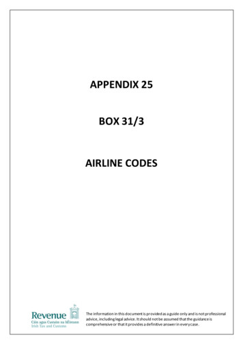
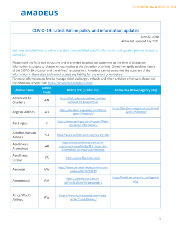
Configuring the Airline Product SetALPS OverviewFigure 1 shows a basic ALPS topology with ALC, UTS, AX.25 and Exchange of Mixed Traffic overX.25 SVCs (EMTOX) protocols. Three major components provide the end-to-end transportation ofairline protocol traffic across the network: the P1024B ALC or P1024C UTS protocol, the TCP-basedtransport protocol, and the AX.25/EMTOX access to the mainframe.Figure 1ALPS with ALC and UTS ArchitectureX.25 links runningAX.25 or EMTOXCentral CPERemote CPEASCUs running ALC or UTSMainframe withairline reservationsystemBackup centralCPERemote CPEASCUs running ALC or UTS51934Networkmanagement systemCPE customer premises equipmentALPS phase III provides support for Mapping of Airline Traffic over Internet Protocol (MATIP). MATIPis an industry standard protocol for transporting airline protocol traffic across a TCP/IP network. Thisenhancement enables the end-to-end delivery of ALC and UTS data streams between a Cisco router andthe mainframe using TCP/IP. ALPS with MATIP removes the X.25 (AX.25 or EMTOX) requirementsfor communication with the host reservation system by enabling TCP/IP communication between therouter and the airline host reservation system.Figure 2 shows the basic ALPS topology and the MATIP architecture implemented in Phase III. Threemajor components provide the end-to-end transportation of airline protocol traffic across the network:the P1024B ALC or P1024C UTS protocol, the TCP/IP-based MATIP protocol conversion, and theTCP/IP access to the mainframe.Figure 2ALPS with MATIP ArchitectureRemoterouterASCUs running ALC or UTS25065Mainframe withairline reservationsystemNetworkmanagement system2RemoterouterASCUs running ALC or UTS
Configuring the Airline Product SetALPS OverviewIn Cisco IOS Release 12.1(2)T and later, ALPS supports service messages additions and extensions tothe ALPS P1024B ALC protocol support. The additions include customized options to configure theformat, address, and sending of service messages. The ALPS ALC support is extended to be morescalable. The ALPS ASCU debug support is extended to include trace capability for the six-bitInternational Programmable Airline Reservation System (IPARS) format.The Cisco ALPS feature provides the following benefits: Provides an end-to-end solution for airlines and central reservation systems. Allows airlines to replace their existing hardware and software with Cisco routers because the ALPSfeature is integrated in the Cisco IOS software. For customers who already use Cisco routers, thisfeature allows them to consolidate networking overhead and functionality. Enables the end-to-end delivery of ALC and UTS data between a remote router or gateway and themainframe using TCP/IP encapsulation. Eliminates network overhead for error detection and transmission logic associated with X.25 links. Replaces IBM front-end processors (FEPs) with Channel Interface Processors (CIPs). Eliminates the use of dedicated, leased, slow-speed ALC and UTS serial lines and migrates thereservation system networks to a modern networking paradigm.Once the mainframe reservationsystem is enabled to use TCP/IP, new applications can be written for PCs or network computers(NCs). Supports standards-based MATIP protocol for transporting data across the TCP/IP network.In Cisco IOS Release 12.1(2)T and later, ALPS includes the following debug, ALC, and service messageenhancements.Debug EnhancementThe ALPS ASCU debug support additions provide new capabilities that enable you to display debugalps ascu command trace output in IPARS format.ALC EnhancementsThe ALPS ALC protocol stack includes the following extensions: Automatic ASCU reset T1 timer range increase Modification of the accepted ASCU IA value listService Message EnhancementsThe additions to the ALPS service messages provide new capabilities that enable you to: Specify sita or apollo service message format Disable the forwarding of service messages for ALPS circuit status changes Specify where to retrieve the terminal address for dropped-data service messages Disable specific service messages Configure service message text with an increased character lengthIn Cisco IOS Release 12.1(3)T and later, ALPS includes the following ALC enhancement.ALC EnhancementThe ALPS ALC protocol stack includes the following extensions:3
Configuring the Airline Product SetALPS Configuration Task List Nonpolled ALC ASCU supportThe ALPS feature supports only type A conversational protocol traffic. The ALPS feature does notsupport MATIP type A host-to-host protocol traffic and MATIP type B messaging protocol traffic.Remote routers must have the Cirrus Logic CD2430 chipset on a synchronous serial interface module toconnect to the ALC or UTS ASCUs. The CD2430 chipset is supported on the following router platforms:Note Cisco 2520, 2521, 2522, and 2523 Cisco 2600 series Cisco 3600 series Cisco 4500 Cisco 4700The Cisco 4500 and Cisco 4700 platforms must have a high-density, low-speed serial card installed.Sixteen low-speed ports are available for performing the remote router functions.The ALPS feature supports the following standards, MIBs and RFCs:Standards P1024B Communication Control Protocol Specification, Societe Internationale deTelecommunications Aeronautiques P1024C Communication Control Protocol Specification, Societe Internationale deTelecommunications Aeronautiques MATIP Implementation Guide, Societe Internationale de Telecommunications AeronautiquesMIBsThe ALPS feature supports the CISCO-ALPS-MIB and the following MIB enhancements: Extensions to the alpsIfP1024Table Extension to the alpsAscuTable Addition of Simple Network Management Protocol (SNMP) notifications for ALPS circuit openrequest failure and ALPS circuit open request with a partial rejectionFor descriptions of supported MIBs and how to use them, see the Cisco MIB website on Cisco.com.RFCs RFC 2351, Mapping of Airline Reservation, Ticketing, and Messaging Traffic over IP, May 1998ALPS Configuration Task ListSee the following sections for configuration tasks for the ALPS feature. Each task in the list indicates ifthe task is optional or required. The tasks in the “Configuring the Remote Routers” section on page 5 arethe only required tasks for ALPS with MATIP.For a complete description of the ALPS commands in this feature module, refer to the “Airline ProductSet Configuration Commands” chapter in the Cisco IOS Bridging and IBM Networking CommandReference (Volume 1 of 2). To locate documentation of other commands, use the command reference masterindex or search online.4
Configuring the Airline Product SetALPS Configuration Task List Configuring the Remote Routers, page 5 (Required) Configuring the Data Center Router, page 9 (Required for EMTOX and AX.25, only) Customizing the Service Messages, page 10 (Optional) Customizing the Alarm Notifications, page 11 (Optional) Updating a Circuit, page 11 (Optional) Verifying ALPS, page 12 (Required)See the “ALPS Configuration Examples” section on page 13 for more information.Configuring the Remote RoutersNoteTo configure ALPS with MATIP, you must perform only the following tasks. The tasks also apply toEMTOX and AX.25, but are not required.Perform the tasks in the following sections to configure the ALPS feature on the remote routers: Specifying the ALPS Local Peer IP Address, page 5 Specifying the ALPS Remote Peer IP Address, page 5 Specifying the ALPS Circuit, page 6 Specifying Each ASCU, page 7Specifying the ALPS Local Peer IP AddressYou must identify an IP address as an ALPS local peer on the remote router. Only one ALPS local peeris permitted on a router.To specify the ALPS local peer IP address, use the following commands in global configuration mode:CommandPurposeStep 1Router(config)# alps local-peer ipaddress[promiscuous]Specifies an IP address to use as the ALPS localpeer on the remote router.Step 2Router(config)# alps keepalive [interval time][retry count]Enables TCP keepalives for ALPS TCP peerconnections.Specifying the ALPS Remote Peer IP AddressYou must specify a partner IP address (remote peer) on the remote router. The peer connection may bepermanent or dynamic (established on demand). You can configure an ATP connection to be permanentor dynamic by configuring the optional dynamic keyword.NoteMATIP sessions are dynamic, whether or not the dynamic keyword is configured. To simulate apermanent connection in MATIP, configure the dynamic keyword with an inact-timer value of zero.5
Configuring the Airline Product SetALPS Configuration Task ListTo specify the partner IP address for one or more TCP peer connections to the configured IP address, usethe following command in global configuration mode:CommandPurposeRouter(config)# alps remote-peer ip-addr [protocol {atp matip-a}] [status-interval interval] [status-retryretries] [dynamic [inact-timer] [no-circuitno-circ-timer]] [tcp-qlen [num]]Specifies the partner IP address. If you select the ATPprotocol, you must configure the data center routers.Specifying the ALPS CircuitAn ALPS circuit is a communication path across a TCP connection for one or more ASCUs. The ALPScircuit must have a configured association with an ALPS remote peer to establish a connection to thehost. Additionally, an ALPS circuit configuration may specify a different remote peer as a backup peerto the host. Each MATIP circuit maps to a single TCP connection. For ATP, ALPS circuits can bemultiplexed across to a single TCP connection.To specify an ALPS circuit, use the following commands beginning in global configuration mode:CommandPurposeStep 1Router(config)# alps circuit nameSpecifies an ALPS circuit at the remote router andenters ALPS circuit submode.Step 2Router(config-alps-circ)# alps primary-peer ip-addr[backup-peer ip-addr]Specifies the primary TCP peer and an optionalbackup peer for this ALPS circuit.Step 3Router(config-alps-circ)# alps local-hld loc-hldremote-hld rem-hldSpecifies the local high-level designator (HLD) forthis ALPS circuit. The remote-hld keyword is notapplicable for ALPS with MATIP. The loc-hld isthe hld of the device that is being replaced. Therem-hld is the hld of the host mainframe.Step 4Router(config-alps-circ)# alps hostlink number {ax25lcn emtox x121-addr} [winout val1] [winin val2] [opsval3] [ips val4]Specifies information required to establish an X.25virtual circuit at the central CPE.Step 5Router(config-alps-circ)# alps connection-typepermanent [retry-timer](Optional) Specifies that this circuit should beestablished when the circuit is enabled.Step 6Router(config-alps-circ)# alps lifetime-timer timer(Optional) Specifies how long messages can bequeued in the ALPS circuit queue.Step 7Router(config-alps-circ)# alps service-msg-intervalseconds(Optional) Specifies the interval between thetransmission of a service message to an ASCU andthe transmission of a PLEASE RETRY message.The PLEASE RETRY message is transmitted onlyto ASCUs that use circuits with a dynamicconnection type.Step 8Router(config-alps-circ)# alps service-msg-list list(Optional) Defines the service message list to beused for this circuit.Step 9Router(config-alps-circ)# alps matip-close-delay time(Optional) Specifies the interval between theclosing and reopening of the MATIP circuitconnection.6
Configuring the Airline Product SetALPS Configuration Task ListCommandPurposeStep 10Router(config-alps-circ)# alps idle-timer timer(Optional) Specifies (for dynamic circuits) thelength of time that can elapse before an idle circuitis disabled.Step 11Router(config-alps-circ)# alps mpx {group single}hdr {a1a2 none}(Optional) Specifies the multiplexing and theASCU identification header for this circuit.Step 12Router(config-alps-circ)# alps enable-circuitEnables the circuit.Specifying Each ASCUYou must configure each ASCU within the context of the serial interface configuration. You mustconfigure ASCU addressing information and association with an ASCU. You can configure the timers,maximum frame sizes, retry values, and polling mode optional configuration parameters for each ASCU.Appropriate default parameters are used for unspecified parameters. Once you configure the first ASCU,you can configure additional ASCUs using only Steps 8 through 14.To specify an ASCU, use the following commands beginning in global configuration mode:CommandPurposeStep 1Router(config)# interface type numberConfigures an interface and enters interfaceconfiguration mode.Step 2Router(config-if)# encapsulation [alc uts]Specifies the protocol to be used on the serialinterface.Step 3Router(config-if)# alps t1 delay(Optional) Specifies the timeout delay between thetransmission of an ALC poll message and the receiptof the first character of the poll message response.Step 4Router(config-if)# alps t2 delay(Optional—ALC only) Specifies the timeout delaybetween receipt of the first character of the response toa poll message and the receipt of a Go Ahead message.Applies to ALC, only.Step 5Router(config-if)# alps n1 errors(Optional) Specifies the threshold of consecutiveerrors logged before an ASCU is declared down.Step 6Router(config-if)# alps n2 polls(Optional) Specifies the number of polls that must becorrectly replied to before an ASCU is declared up.Step 7Router(config-if)# alps n3 value(Optional—UTS only) Specifies the maximumnumber of retransmissions of an unacknowledgedoutput data message to an ASCU. Applies only toUTS.Step 8Router(config-if)# alps servlim polls(Optional) Specifies the number of cycles of the activepoll list to execute before polling the next ASCU onthe inactive poll list.Step 9Router(config-if)# transmitter-delay delaySpecifies number of padding characters added to theend of the frame (minimum dead-time aftertransmitting a packet).7
Configuring the Airline Product SetALPS Configuration Task ListStep 10CommandPurposeRouter(config-if)# half-duplexSpecifies half-duplex mode on a serial interface.This command specifies whether hardware flowcontrol (constant or switched Request to Send [RTS])is to be used between a DTE and DCE device. If half-duplex is specified for a DTE, the DTEraises RTS and waits for the DCE to raise Clear toSend (CTS) before sending. If half-duplex is specified for a DCE, the DCEwaits for the DTE to raise RTS, then the DCEraises CTS to allow the DTE to send. If full-duplex is specified, RTS is assumed andCTS is not monitored.NoteALPS supports the serial interface commandsthat are available if half-duplex mode isspecified. This support applies to an interfacethat is configured as data circuit-terminatingequipment (DCE) and data terminal equipment(DTE).Step 11Router(config-if)# alps poll-pause msec(Optional) Specifies the minimum interval, inmilliseconds, between initiations of the polling cycle.Step 12Router(config-if)# alps service-msg data-drop{msg-term config-term}(Optional) Specifies where to retrieve the terminaladdress to use when a service message is sent to anASCU as a result of a dropped data message from aterminal.Step 13Router(config-if)# alps service-msg format {sita apollo}(Optional) Specifies the protocol format of servicemessages sent from the router to an ASCU.Step 14Router(config-if)# alps service-msg status-change(Optional) Specifies that service messages for ALPScircuit status changes will be sent to ASCUs on theserial interface.Step 15Router(config-if)# alps ascu idSpecifies a physical ASCU identity (the ASCUinterchange address value for ALC) and enters ALPSASCU submode.Step 16Router(config-alps-ascu)# alps default-circuitnameSpecifies the ALPS circuit that this ASCU uses.Step 17Router(config-alps-ascu)# alps a1-map a1-valuea2-map a2-valueSpecifies the A1 and A2 logical ASCU identificationinformation.Step 18Router(config-alps-ascu)# alps retry-option[resend reenter](Optional) Specifies the retry option when an ALCmessage with a bad cyclic check character (CCC) isreceived.Step 19Router(config-alps-ascu)# alps max-msg-lengthvalue(Optional) Specifies maximum input message length.8
Configuring the Airline Product SetALPS Configuration Task ListStep 20CommandPurposeRouter(config-alps-ascu)# alps error-displaynumber1 number2(Optional) Specifies where error messages aredisplayed: For P1024B ALC, the number1 argumentspecifies the terminal address (TA) where theseservice messages are sent and the number2argument specifies the screen line number whereservice messages are displayed. For P1024C UTS, the number1 argument specifiesthe screen line number where service messages aredisplayed and number2 argument specifies thecolumn number where service messages aredisplayed.Step 21Router(config-alps-ascu)# alps auto-reset(Optional) Automatically resets non-responsive ALCASCUs in the DOWN state.Step 22Router(config-alps-ascu)# alps aliasalias-interchange-address(Optional) Specifies that an ALC ASCU is to operatein nonpolling mode and specifies the parent ASCUinterchange address to which this ASCU is aliased.Step 23Router(config-alps-ascu)# alps enable-ascuPolls the ASCU.Configuring the Data Center RouterNoteThese tasks apply to EMTOX and AX.25, only.Perform the tasks in the following sections to configure the ALPS feature on the data center router: Specifying the ALPS Host Local Peer Address, page 9 Specifying AX.25, page 10 Specifying EMTOX, page 10Specifying the ALPS Host Local Peer AddressYou must identify an IP address to use as the ALPS local peer IP address. Only one ALPS host local peeris permitted on a router. The promiscuous option, which allows any remote router to connect, isrecommended at the central CPE.To specify the ALPS host local peer address, use the following command in global configuration mode:CommandPurposeRouter(config)# alps local-peer ip-address [promiscuous]Specifies the IP address of the local peer.9
Configuring the Airline Product SetALPS Configuration Task ListSpecifying AX.25To enable AX.25 on an X.25 interface, the ALPS host HLD and hostlink number must be configured andAX.25 must be specified on an X.25 serial interface. At circuit-establishment time, the remote routerforwards the host HLD, the logical channel number (LCN), and the hostlink number for the permanentvirtual circuit (PVC), to be used for the ASCU group.To configure AX.25 on an X.25 interface, use the following commands beginning in global configurationmode:CommandPurposeStep 1Router(config)# interface type numberConfigures an interface and enters interfaceconfiguration mode.Step 2Router(config-if)# encapsulation x25Specifies a serial interface as an X.25 device.Step 3Router(config-if)# alps host-hld hld host-linknum {{ax25 [damp-tmr value]} {emtox x.121[pseudo-conv]}} [life-tmr value]Enables ALPS on the X.25 interface.Specifying EMTOXTo enable EMTOX on an X.25 interface, the host HLD and the hostlink number must be configured andEMTOX must be specified on an X.25 serial interface. At circuit-establishment time, the remote routerforwards the X.121 address to be used as the calling address in the X.25 call and the host HLD and thehostlink number. If the host performs a call out, a correlation between the X.121 called address and aremote router peer IP address must be configured.To configure EMTOX on an X.25 interface, use the following commands beginning in globalconfiguration mode:CommandPurposeStep 1Router(config)# interface type numberConfigures an interface and enters interfaceconfiguration mode.Step 2Router(config-if)# encapsulation x25Specifies a serial interface as an X.25 device.Step 3Router(config-if)# alps host-hld hld host-link num{{ax25 [damp-tmr value]} {emtox x.121[pseudo-conv]}} [life-tmr value]Enables ALPS on the X.25 interface.Step 4Router(config-if)# alps translate x.121-addrip-addrMaps an X.121 address to an IP address on a remotepeer.Customizing the Service MessagesYou can customize the contents of the service messages and service message list. To specify the servicemessage number and the content of the message, use the following command in global configurationmode:CommandPurposeRouter(config)# alps service-msg-list list number number msgSpecifies service message numbers and content.10
Configuring the Airline Product SetALPS Configuration Task ListNoteThe default service message is used if no service message list number is specified. If you configure aparticular service message on a list, the default service message still is used for the rest of the messageson that list.NoteOnce the alps service-msg-list number command has been configured, you can define the servicemessage list to be used on the circuit by configuring the alps service-msg-list command.NoteYou can configure the handling of service messages using the alps service-msg data-drop, alpsservice-msg format, and alps service-msg status-change interface configuration-level commands.Table 1 shows the default service message text strings:Table 1Service Message Default Text StringsMessageNumber EventText String1ALPS circuit to host is opened.CONNECTION UP2X.25 virtual circuit at the host has been cleared.DISC BY THE HOST3X.25 interface at the host is down.HOST ISOLATED4No response from the host router when trying to establish aconnection.NETWORK PROBLEM5Connection to host was disconnected because of inactivity.READY TO CONNECT6Network is congested.CONGESTION7Network congestion has cleared.PLEASE PROCEED8Network operator has disabled the path to the host.DISC BY NET OPERATCustomizing the Alarm NotificationsYou can enable and customize alarms (error messages) and SNMP traps. To enable and customize alarmsfor the ALPS ASCUs, circuits, or peers, use the following commands in global configuration mode:CommandPurposeRouter(config)# alps enable-alarms ascu [interface id]Enables alarms for the ALPS ASCUs.Router(config)# alps enable-alarms circuit [name]Enables alarms for the ALPS circuits.Router(config)# alps enable-alarms peer [ip-address]Enables alarms for the ALPS peers.Updating a CircuitYou can clear or update the circuits on the ALPS network. If a specific name is entered, the update actionwill be executed only on a configured circuit with that name; otherwise, the action will be performed onall configured circuits. If the circuit uses the ATP protocol, an update consists of a closing and reopening11
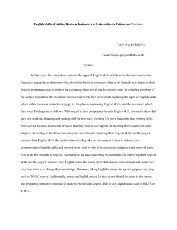
Configuring the Airline Product SetALPS Configuration Task Listof the ALPS circuit (the same action performed when clearing the circuit). If the circuit is a MATIPcircuit, the update results in the sending of a configuration update (in the form of a MATIP Session Opencommand). You can update the circuit only on enabled or active (opened or opening state) ALPS circuits.To update one or more ALPS circuits, use the following command in EXEC mode:CommandPurposeRouter# alps update-circuit [name]Specifies name of circuit to update.Verifying ALPSPerform the tasks in the following steps to verify the components of the ALPS network:Step 1Verify that the connection between the router and the ASCU is up by polling the ASCU. Enter the showalps ascu command and check the state field. UP indicates that the ASCU is responding to the polling.DOWN indicates that the connection is not responding to the polling.router# show alps ascuinterfacedlcida1a2circuitpkt tx pkt rx 26070CKT ALC 1 416416UPSerial6ALC456072CKT ALC 1 600600UPSerial6ALC486278CKT ALC 2 00DOWNSerial7UTS212213CKT UTS48304830UPStep 2Verify that the peer between the router and the host is connected. Enter the show alps peer commandand check the state field. OPENED indicates that the circuit is connected. DISCONN indicates that thecircuit is disconnected.router# show alps peerslocal peer : ip address 192.168.25.2ip addressconn idstatepkt t pkt TIP A CKT UTSOPENED10231023192.168.70.2MATIP A CKT ALC 1OPENED48524757192.168.70.2MATIP A CKT ALC 2OPENED11192.168.70.3MATIP A CKT ALC 1DISCONN 00192.168.70.3MATIP A CKT ALC 2DISCONN 00Step 3Verify that the ALPS circuit to the peer host is open and connected. Enter the show alps circuitscommand and check the state field. OPEN indicates that the circuit is connected. INOP indicates that thecircuit is disconnected.router# show alps circuitsnamepri peercurr peerdlcstate pkt tx pkt ------------------------------------ALC EMTOX192.168.45.2192.168.45.2ALCOPEN944944UTS AX25192.168.45.2192.168.45.2UTSOPEN42542512
Configuring the Airline Product SetMonitoring and Maintaining ALPSMonitoring and Maintaining ALPSTo monitor the status of the ALPS feature, use the following commands in EXEC mode:CommandPurposeRouter# show alps ascu [interface] [id] [detail]Displays the status of the ALPS ASCU.Router# show alps circuits [peer ip address] [name name][detail]Displays the status of the ALPS circuits.Router# show alps peers [ipaddress addr] [detail]Displays the status of the ALPS remote peers.ALPS Configuration ExamplesThis section provides the following configuration examples: ALPS with MATIP Configuration for ALC and UTS Example, page 14 ALPS Configuration for ALC and AX.25 Example, page 16 ALPS Configuration for UTS and EMTOX Example, page 1813
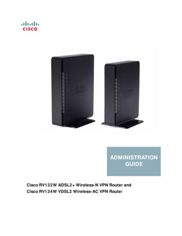
Configuring the Airline Product SetALPS Configuration ExamplesALPS with MATIP Configuration for ALC and UTS ExampleFigure 3 shows a simple example of a router topology for the ALPS with MATIP feature. Theconfiguration corresponding to this topology follows.Figure 3IBM mainframe192.168.70.2(primary peer)Router Topology for the ALPS with MATIP Configuration ExampleIBM mainframe192.168.70.3(backup peer)IA 42IA 45ASCUs running ALCs6Frame Relays0s7Unisys host system192.168.20.3ASCU running UTSRID 2151935Remote router192.168.25.2IA interchange addressRID remote identifierALC/UTS Router Configuration(config)# hostname alps-rcpe(config)# alps local-peer 192.168.25.2(config)# alps keepalive interval 45 retry 2(config)# alps remote-peer 192.168.20.3 protocol matip-a dynamic status-interval 60(config)# alps remote-peer 192.168.70.2 protocol matip-a dynamic 0 no-circuit 10(config)# alps remote-peer 192.168.70.3 protocol matip-a dynamic 45(config)# alps enable-alarms peer 192.168.70.2(config)# alps enable-alarms ascu!(config)# alps circuit CKT ALC 1(config-alps-circ)# alps primary-peer 192.168.70.2 backup-peer 192.168.70.3(config-alps-circ)# alps connection-type permanent(config-alps-circ)# alps local-hld 2525(config-alps-circ)# alps enable-circuit!(config)# alps circuit CKT UTS(config-alps-circ)# alps primary-peer 192.168.20.3(config-alps-circ)# alps mpx single(config-alps-circ)# alps idle-timer 90(config-alps-circ)# alps local-hld 2527(config-alps-circ)# alps enable-circuit(config-alps-circ)# alps service-msg-interval 2!(config)# interface Loopback0(config-if)# ip address 192.168.25.2 255.255.255.0(config)# interface Serial0(config-if)# ip address 210.100.50.2 255.255.255.014
Configuring the Airline Product SetALPS Configuration Examples(config-if)# encapsulation frame-relay IETF(config-if)# frame-relay map ip 210.100.60.2 40(config-if)# frame-relay map ip 210.100.70.2 50!(config)# interface Serial6(config-if)# encapsulation alc(config-if)# alps t1 6(config-if)# alps t2 8(config-if)# alps poll-pause 100(config-if)# clockrate 9600!(config-if)# alps ascu 42(config-alps-ascu)# alps default-circuit CKT ALC 1(config-alps-ascu)# alps a1-map 60 a2-map 70(config-alps-ascu)# alps enable-ascu!(config-if)# alps ascu 45(config-alps-ascu)# alps default-circuit CKT ALC 1(config-alps-ascu)# alps a1-map 60 a2-map 72(config-alps-ascu)# alps enable-ascu!(config)# interface Serial7(config-if)# encapsulation uts(config-if)# alps n3 4(config-if)# alps poll-pause 125(config-if)# clockrate 4800!(config-if)# alps ascu 21(config-alps-ascu)# alps default-circuit CKT UTS(config-alps-ascu)# alps a1-map 22 a2-map 13(config-alps-ascu)# alps enable-ascu!15
Co
the mainframe using TCP/IP. ALPS with MATIP removes the X.25 (AX.25 or EMTOX) requirements for communication with the host reservation system by enabling TCP/IP communication between the router and the airline host reservation system. Figure 2 shows the basic ALPS topology and the MATIP architecture implemented in Phase III. Three