Transcription
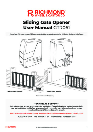
Sliding Gate Opener User ManualModel: GTR156Please Note: This motor is AC 240V Power only and is not compatible with DC Battery Backup or Solar power.Gate in closed positionGate in open positionWARNINGInstructions must be read before beginning installation. Please follow these instructions carefully, incorrectinstallation could affect gate operation. If you require more information, please contactRichmond Wheel & Castor Co on 1300 474 246When mounting and positioning the motor ensure that the power cable is unplugged. The motor cover will need tobe removed to mount the motor to the mounting plate. Any changes to the settings of the gate motor can only bemade by a licensed electrician.Revision 19a1
Revision 19a2
Contents:Gate Opening Default Setting Information . . .4General Safety . . . .5Parts List . . .6Technical Specifications 7Motor InstallationBefore you start . 8Tools Required / Example Sliding Gate Setup . 9Step 1 - Gate Preparation Before Adding Your Motor . .10Step 2 – Motor Pad Footing . .10Step 3 - Motor Position Installation . . 11Step 4 – Removing Motor Cover for Mounting . .12Step 5 – Drilling Holes for Anchor Bolts . . .12Step 6 – Fitting the Mounting Plate & Motor . .13Step 7 – Gear Rack & Motor Alignment .14Step 8 – Limit Travel Stops .16Step 9 – Powering the Motor .18Step 10 – Testing the Limit Travel Stops . .19Programming and WiringControl Board Diagrams . 20Dip Switch Adjustment 22Further Settings and Programming . 23Connecting Infrared Photocells .26Maintenance . .27Troubleshooting . 28Pairing and Clearing Remotes 29Additional Drawings and Diagrams . 30Revision 19a3
Gate Opening Default Setting Information:The gate motor will close the gate to the right-hand side as its default setting (refer to fig 1).Default operation:Motor mounted on theleft-hand sideFig 1Before Installing: Test the motor by plugging it into a power source and pressing the remote. You will see themotor cog turn. When it stops, press the remote again to see it turn in the opposite direction. This will give you anunderstanding of the way in which the motor will move the gate.Press the first/top button on the remote.The motor cog will turn counterclockwise, moving the gate frameforwards.The gate will then move in the setdirection. Default: right-hand close.Note: Ensure that the motor is unplugged before proceeding with installation. Please keep fingers awayfrom the motor cog whilst it is turning.If your gate needs to open from the other direction (to the left, refer to fig 2) and, your motor is on theright-hand side, a qualified electrician will need to switch the MOT1 and MOT2 wires on terminal J4(refer to pages 20 and 21).Fig 2Left-Hand Opening:Motor mounted on theright-hand sideAny works done to the motor must be completed whilst the power is off, and the motor is unpluggedRevision 19a4
Thank you for choosing this sliding gate opener. Please read the manual carefully beforeassembling and using it. Do not leave out the manual if you send this product to a third party.This product complies with the recognised technical standards and safety regulations. Ourcompany has the right to change this manual without prior notice.General Safety:Warning: Incorrect or improper use of this product can cause damage to persons, animals orproperties. Please ensure that the input voltage used matches with the supply voltage of gate opener(AC240V 50Hz). All modifications to wiring or electrics, and any adjustment or maintenance to 240VAC MUSTbe done by a qualified electrician. To avoid damaging gas, power or other underground utility lines, contact the relevant authorityBEFORE digging. All potential hazards and exposed pinch points of the gate must be eliminated or guarded priorto installation of this gate motor. Never mount any device that operates the gate motor where the user can reach over, under,around or through the gate to operate the controls. These must be placed at least 1.8m fromany moving part of the moving gate. Ensure power plug is disconnected from the power socket during installation or maintenance. Keep remote control and other control devices out of children’s reach, in order to avoidunintentional activation. Never allow anyone to hang onto the gate while moving. Please ensure a warning sign provided is fitted to the structure. To ensure safety, before installing the main motor, mount a Gate End Stop (GTR017) and a GateStopper (GTR017 or GTR018) at each end of the rail to prevent the gate travelling off the track. If required, install infrared photocells (GTR051, sold separately) to detect obstructions andprevent injury or damage. Instruct all users about the control systems provided and the manual opening operation in caseof emergency. Ensure that the power cable is connected to a RCD protected weatherproof power outletinstalled by a qualified electrician. Do not install the product in an explosive atmosphere or where there is any danger of flooding. This product was exclusively designed and manufactured for the use specified in the presentdocumentation. Any other use not specified in this documentation could damage the productand be dangerous. Only use original parts for any maintenance or repair operation. Richmond Wheel & Castor Codeclines all responsibility with respect to the automation safety and correct operation whenother supplier’s components are used. Do not modify the automation components, unless explicitly authorised by Richmond Wheel &Castor Co. The user must avoid any attempt to carry out any works or repairs on the motor, and shouldalways request the assistance of qualified personnel. This motor is suitable for use on one sliding gate only. Anything which is not expressly provided for in these instructions is not allowed and will voidwarranty. Dispose of all packing materials (plastic, cardboard, polystyrene etc.) according to currentguidelines. Keep plastic bags and polystyrene out of children’s reach. Save these instructions for future use.Revision 19a5
Parts List:No.PictureNameMain motor12Motor Mounting Plate3Manual release keysRemote controls(factory paired to motor)45Gate Warning Signage6In the accessories boxyou will find the itemsbelow:6aLimit travel stops6bLimit travel stopmounting screw M6x186cMasonry Anchor boltM12x100mm( Drill bit size: M12 Masonry )6dMotor mounting setscrews, nuts, spring &flat washers M10 x50mmRevision 19a6Quantity1122112444
Technical Specifications:ModelGTR156Power supply240VAC/50HzMotor power400WGate moving speed11-13m/minMaximum weight of gate1200KgMaximum length of gate12mRemote control distanceUp to 30mRemote control modeSingle Button ModeLimit switchSpring Limit SwitchNoiseUp to 60dBWorking dutyS2 - 20min (20 minutes maximum continuous operation)IP RatingIP45Maximum # Remote Controls25Remote Control Frequency433.92 MHzWorking temperature-20 C 70 CPackage weight15Kg7Revision 19a
Motor Installation:Before you start: The GTR156 Sliding Gate Automation Kit is suitable for powering the opening andclosing motion of gates up to 1200kg in weight, up to a length of 12m.Gate motion is achieved by the rotating cog of the gate motor driving the gear rackfitted to the moving gate.The gate motor itself must be fitted within private property, never externally to a property’sboundary.Power Supply: The GTR156 requires 1 x 10Amp AC240V 50Hz power supply (RCD ProtectedWeatherproof PowerPoint). The GTR156 comes complete with a power lead and plug that is 1m long.If you do not have a suitable RCD protected weatherproof power point within 1m of the gate motor youwill need to consult a licenced electrician.Any works done to the motor must be completed whilst the power is off and the motor isunplugged.Any modifications/alterations/works to the 240V AC power components must only becompleted by a licensed electrician for your state/country.Please Note:Your weatherproof power outlet should be no more than 1m from the electricgate motor.If your weatherproof power outlet is more than 1m from the gate motor, you willrequire a licensed electrician to fit a new power cable.Any excess cable length should be cable tied and secured out of the way ofmoving objects.8Revision 19a
For Installing Your Gate Motor, You Will Need: Power drillTape measureLevel12mm Masonry Drill Bit (for the 4 motor masonry anchor bolts)Socket and Spanner SetPhillips Head ScrewdriverExample Sliding Gate Setup:GateStopperGate EndCatchGate GuideRollersGate Track andTrack WheelsIf you require any gate hardware, contact Richmond Wheel & Castor Co or an authorised reseller.9Revision 19a
Please ensure that the motor power cable is not plugged in at any stage before Step 9Step 1 - Gate Preparation Before AddingYour Sliding Gate Motor: Ensure that the sliding gate is correctly installed.The gate is horizontal and level and the gate can glide back and forth smoothlywhen moved by hand before installing the automatic gate opener.Wheels and guide rollers should rotate easily and be free from dirt/grime.Track should be flat, level and firmly affixed.Any misalignment in the gate will affect performance of the automatic gateopener.The gate should slide smoothly by hand before attempting to install the gate opener.Step 2 - Motor Pad Footing (Minimum Requirement): The motor pad concrete footing requires an area of no less than 450mm long x300mm wide and a minimum depth of 200mm (Standard requirement).Ensure surface is level and parallel to the drivewayMounting Plate Dimensions:10Revision 19a
Step 3 - Motor Position Installation: Insert the key and open the manual release bar to put the motor into manualmode, and check that the motor cog rotates freely by hand (As per Fig 16).Place the motor and motor mounting plate on the concrete pad.Make sure the distance between the gate motor cog and gear rack position arealigned (see Fig 4)Mark all four outside corners of the mounting plate on the concrete pad using apencil, chalk or similar, to ensure the mounting plate is in the correct positionbefore drilling.Remove motor from the mounting plate.Fig 3Sliding Gate FrameMarkcornersof themountingplate witha pencil,chalk, orsimilar.Fig 411Revision 19a
Step 4 – Removing Motor Cover for Mounting: Unscrew the two motor cover screws located at each side of the motor cover.Remove the rubber grommet below the spring limit switch (as per fig 5).Fig 5Please Note: the rubber grommet must be fitted back onto the motor cover once thecover has been re-fitted/replaced onto the base of the motor.Step 5 - Drilling Holes for Anchor Bolts: Ensure the mounting plate is positioned within the marked corners.Proceed to mark the (4) positions for your anchor bolts ready for drilling (refer toFig 6).Remove Mounting plate.Using a M12 masonry drill bit, drill holes to a minimum depth of 120mm (Fig 7). Mark anchor bolt positionsFig 6Fig 712Revision 19a
Step 6 - Fitting Mounting Plate & Motor: Fit motor mounting plate back into place and fit and tighten anchor bolts (as perfigures 8 an 9).Fit motor back on mounting plate, ensuring the power cord is positioned into theend slot of the mounting plate in the direction of the power point, making surethere are no pinch points (as per Fig 10).Slide rubber grommet along the power cable and into the end slot of the mountingplate (as per figures 11 and 12).Bolt motor to the mounting plate using the M10 x 50mm bolts with spring and flatwashers provided and tighten as required (as per figure 13).Tighten bolts usingspanner or socket setFig 8Fig 10Fig 9Fig 11Fig 12Insert the M10 x 50mm (Part 6d)bolts, spring washers, and flatwashers provided through motorhousing and screw into weldednut on the baseplate.Hand-tighten set screws beforefinal adjustment of motor.Fig 13Please ensure that the motor power cable is not plugged in at any stage before Step 913Revision 19a
Step 7 - Gear Rack & Motor Alignment: See Fig 16 for recommended gear rack mounting height.Insert the key and open the manual release bar to put the motor into manualmode and check that the motor cog rotates freely by hand (as per Fig 16).Ensure that the gate drive cog has a minimum clearance of 1-2mm along theentire length of gear rack fitted to the gate (as per Fig 14).Ensure motor cog and gear rack are correctly aligned. Under no circumstancesshould the gate motor drive cog carry any weight of the gate. It is the task of thegate castors or wheels to carry the weight of the gate (as per Fig 15).If the gate doesn’t slide freely by hand, adjust the height of the gear rackaccordingly until the full length of gate slides freely by hand.Gear rack correctly aligned at 90 to themotor cogFig 15Fig 14Gear rack misaligned. Do not attempt touse if misaligned.At this stage of assembly, the cover is removed (not shown) and the power cable is still unplugged.Fig 1614Revision 19a
At this stage of final assembly, the cover is removed (not shown) and the power cable isstill unplugged.Fig 17Now that your gear rack and motor are aligned, and your gate issliding freely, fully tighten the motor mounting set screws (Part6d) and reinstall motor cover and tighten screws provided.15Revision 19a
Step 8 - Limit Travel Stops:Included in your gate motor kit are two limittravel stops (Part 6a) which must be fitted tothe gear racks on your gate to ensure safeoperation.The limit travel stops are designed to set thedesired opening and closing position of yourgate. These limit travel stops are designed tocome into contact with the spring limit switch.Please note; gates can open and close indifferent positions due to different weights ofgates, terrains, slopes (uphill or downhill). Thedistance the gate will travel after contactingthe spring limit switch may vary.Fig 18Setting the Limit Travel Stops:Closed Position Position gate 150-200mm back fromthe gate end catch closed position.This will help in making sure you do notslam the gate into the end stop/catchwhen setting the closed position underpower.Fit limit travel stop onto the top of gearrack at the point where it meets thespring limit switch on the motor.Tighten locking screws.Fig 19Open Position Position gate 150-200mm back fromthe gate stopper open position. This willhelp in making sure you do not slam thegate into the end stop/catch whensetting the open position under power.Fit limit travel stop onto the top of gearrack at the point where it meets thespring limit switch on the motor.Tighten locking screws.Fig 20Test the spring limit travel stops by moving the gate manually until you hear a click,making sure contact is made with the spring limit switch on the motor.16Revision 19a
The installation of spring limit switch block is shown in Figure 21Fig 22Please Note:The warningsignage provided(Part 5) must bedisplayed on thestreet facing sideof your automaticgate at all times.Fig 2317Revision 19aFig 21
Step 9 - Powering the Motor: Ensure that the outer cover has been fitted and fastened back onto the motorhousing.Before powering up the motor make sure the gate can travel by hand in manualmode (key unlocked).The gate must be put in the open position before locking the key (key locked) inreadiness for automatic mode.Plug the power cord into an approved RCD protected weatherproof outlet.Remote controls (Part 4) included in this kit are factory paired ready for use.Note: The default setting is closing to the right. If you want the gate to close to the left,then you will need to change the direction of opening by switching the MOT1 andMOT2 lines on the J4 terminal (as per fig 25). Soft start/soft stop function - The GTR156 is set by default to provide the softstart/soft stop function. We recommend this default position is always maintained. This must be done when the power is off and unplugged. This must be done by alicensed electrician.Your motor is now set up for basic remote-control operation. To set furtherfunctions and settings, see pages 18-2618Revision 19a
Step 10 – Testing the Limit Travel Stops:Testing the closed position Ensure motor is plugged in as per step 9 and the gate is in the open position. Press remote (remotes included in kit are factory paired to the motor). The gatewill begin to close. The limit travel stop will hit the spring limit switch and the gate will stop. When the gate stops, measure the distance remaining between the gate and thedesired closed position. You have now determined the closed position of the gate when the travel limitstop hits the spring limit switch. Adjust the limit travel stop from the measurement you have taken to get yourfinal gate closed position. The ideal closed final position for the gate frame is 1015mm from closed gate end catch (GTR019).Testing the open position Press remote. The gate will begin to open. The limit travel stop will hit the spring limit switch and the gate will stop. When the gate stops, measure the distance remaining between the gate and thedesired open position. You have now determined the open position of the gate when the travel limit stophits the spring limit switch. Adjust the limit travel stops from the measurement you have taken to get yourfinal gate open position. The ideal open final position for the gate frame is 1015mm from the gate stopper (GTR017).Fig 2419Revision 19a
Programming and Wiring:Control board wiring diagram 01Any works to the 240V AC must only be performed by a licensed electrician.Ensure power is off before any modifications are made.Fig 25Revision 19a20
Programming and Wiring:Control board wiring diagram 02Please refer topage 24 for addeddescription ofterminals J2 & J5Fig 26Revision 19a21
Dip Switch Adjustment:All changes to these settings must be completed by a licensed electricianNumberDescriptionSoft Start/Close FunctionOFF – enabledON – disabledDefault position is OFF (recommended)Limit Switch Setting (disable or enable the spring limit switch)OFF – Normal OpenON – Normal CloseDefault position is ON, this should not be changed.Automatic Close Function3 OFF 4 ON: automatic close delay time is 12s.3 ON 4 OFF: automatic close delay time is 24s.3 ON 4 ON: automatic close delay time is 36s.3 OFF 4 OFF: no automatic close function. Gate will remain open untilclosed again with a remote.Once the gate has been opened by the remote, pressing the remote buttonagain will close the gate.3 ON 4 OFF: Hard wire keypad. Automatic close function.Stall Force Mode (When in default position, detects obstacles, stopsgate, and reverses. To adjust, refer to VR1: Stall Force Mode)Default position is OFF (enabled) this should not be changed.If the switch is set to ON, stall force mode will be disabledRevision 19a22
Further Settings & Programming:All changes to these settings must be completed by a licensed electricianVR1: Stall Force ModeMaximum More Force Less sensitiveMinimum Less Force More sensitiveWhen Stall Force Mode is enabled (Dip switch 5 is at OFF position), the motor willdetect obstacles and impacts to the gate. If this is during opening, the gate will stop, ifthis is during closing the gate will stop, and then re-open.Rotate VR1 clockwise to increase the stall force, anti-clockwise to decrease.For safety we strongly recommend that Stall Force Mode is left enabled (Dip switch 5 isat the OFF position). Do not turn Dip switch 5 to the ON position.VR2: Brake Force AdjustmentFor adjusting brake force at the limit position during gate opening and closing. Thisshould only be adjusted for heavy gates that need additional force to brake when limitswitch is detected.Rotate VR2 clockwise to increase, counter-clockwise to decrease. Default setting is atminimum.VR3: Slow Start/Stop Width AdjustmentThis switch controls how many seconds the motor operates at maximum speed. RotateVR3 clockwise to increase, rotate counter-clockwise to reduce.Default setting is at minimum.VR4: Motor Output Force AdjustmentFor best performance set the torque at the lowest setting that you require.Rotate clockwise to increase, counter-clockwise to decrease.Default setting is at maximum.Revision 19a23
All changes to these settings must be completed by a licensed electricianJ2 Terminal: (as per fig 17)Terminal 1: Optional External Close Push Button Switch.Terminal 2: Optional External Open Push Button Switch.Terminal 3: Optional External Stop Push Button Switch.Terminal 4: Common Terminal for All Optional Push Buttons.(Hard-Wired keypad connection between terminals 4 & 5)Terminal 5: Optional External Open/Stop/Close Single Push Button(does the 3 open/stop/close functions)Terminal 6: Optional External Push Button Pedestrian SwitchJ5 Terminal: Limit Switch and AccessoriesAdditional accessories sold separatelyTerminal 7: Power supply for accessories of J5 ( 15V)Terminal 8: Photocell input (Normally Closed). If no photocellis fitted use jumper between terminals 8 & 9.Terminal 9: Ground/Earth (GND)Terminal 10: Exit wand connection between terminals 9 & 10Terminals 11, 12, and 13 are factory fitted (pre-wired)Terminal 11: Close spring limit switchTerminal 12: Spring limit switch common terminalTerminal 13: Open spring limit switchConnecting Wires to the Terminal:Using a screwdriver,loosen the screw on theside of the terminal.Revision 19aInsert the wire into thenumber on the terminalthat you are looking toconnect to. Refer toPages 20 & 2124Tighten with ascrewdriver to securethe wire in place.
All changes to these settings must be completed by a licensed electricianJ6 Terminal:Motor CapacitorJ4 Terminal:MOT1: Motor Terminal, swap with MOT2 to change gate direction.MOT2: Motor Terminal, swap with MOT1 to change gate direction.MOTCOM: Motor Common Terminal.LAMP (L&N): Connection for warning lamp.PE: Motor and warning lamp earthJ3 Terminal - Main Power Terminal:PE: Earth (yellow/green wire).L: Power (brown wire).N: Power (blue wire).Revision 19a25
Connecting Infrared Photocells:The below steps must be completed by a licensed electricianRichmond highly recommend the use of infrared photocells as an additional safetyfeature.While closing, if the ray of the Infrared Photocell is blocked, the gate will stop andreverse immediately, to protect user and property security.To install photocells, connect wiring as per Figure 21. You must remove the wire jumperbetween terminal 8 and terminal 9 on J5 (ref to Fig 24 and 25).Dip switch 2 should be set to ON, for Normal Close.Fig 27Before Installing PhotocellsLoosen J5 Terminals 8and 9 with a screwdriver.Make sure the power isdisconnected beforedoing so.Revision 19aRemove the wire jumperbetween J5 Terminals 8 & 926
Maintenance:Under normal operation, the gate should be checked every 6 months: Lubricate shafts and sprockets Check and tighten anchor bolts Check for loose and corroded wires. Check the earth wire (green/yellow) on Terminal J4 (refer to Fig 19 and 20) isfirmly attached to the housing with the screw. This should be checked by aqualified electrician. Always check the stall force after performing any maintenance. If this functiondoes not work, do not use the gate motor until this is rectified.27Revision 19a
Troubleshooting:Any works done to the motor must be completed by a licensed electrician andonly whilst the power is off and the motor is unplugged.ProblemPossible ReasonThe gate cannotopen or closenormally, and LEDdoes not light.1. The power is off.2. Fuse is blown.3.Control PCB is damagedRemote controldoesn’t work.The gate opens butcannot close.Solution1. Switch on the power supply.2. Licensed Electrician: Check the fuse (seepage 17) and replace if necessary.3. Contact Richmond Wheel & Castor Co forreplacement PCB (board)1. Remote control battery is 1. Check LED lights up when button is pressed. Ifflat.not, change the remote-control battery (A272. Remote control is notbattery required)paired correctly.2. Licensed Electrician: Repeat pairing procedure(refer to page 26)1. Stall force is set too low 1. Increase stall force to the minimum value that2. Photocell settings notthe gate still operates. (see page 20)correct.2. Licensed Electrician: If photocell is not3. Photocell beam isconnected, ensure that there is a jumper wireinterrupted (if installed).between 8 and 9 on the J5 terminal. If photocellis connected, ensure the wiring is correct.3. Check and remove any obstructions.Gate does not move 1. Gate is out of alignment. 1.Put motor into manual mode and check if it canwhen button is2. Capacitor has blown or is be opened freely by hand. If not, check that thepressed, but motor otherwise damaged.gear rack freely moves over the motor cog.makes a noise.2. Contact Richmond Wheel & Castor Co forreplacement PCB (board)Gate does not stop at 1. The brackets are1. Check that LEDs 11/13turn off when spring isthe limit switch when positioned incorrectly.contacted and reposition if required.opening/closing.2. The gate opening2. Licensed Electrician: Swap the wires betweendirection is incorrect‘11’ and ‘13’ on the J5 terminal. This must be3. Limit switch is damaged. done while power is disconnected.3. Check wiring for any damage. ContactRichmond Wheel & Castor for a new limit switchif required.Gate does not fully 1. The gate meets an1. Remove the obstacle.open or closeobstacle.2. Licensed Electrician: Increase VR4: Motor2. Motor output force is too Output Force Adjustment (Page 21).low.3. Licensed Electrician: Increase VR1: Stall3. Stall force is too low.Force (Page 21).Revision 19a28
The below steps must be completed by a qualified electricianClearing Remote Controls:To delete all paired remote controls, press and hold the button ‘S1’ for approx. 8seconds. When the ‘LEARN’LED turns off, all previously paired remote controls will bedeleted.Pairing Additional Remote Controls:Remove motor outer cover and continue to remove the clear PCB cover, press thebutton ‘S1’ on the control board, until the ‘LEARN’LED turns on, then release thebutton. While the light is on, press the first button on the remote control twice, the‘LEARN’ LED will flash repeatedly and then turn off when remote control is paired.Press and hold the learnbutton (S1) until the LearnLED flashes ON.While the light is on,press the first button onthe remote control twice.The Learn LED will flashrepeatedly and then turnOFF. when the remote ispaired.Technical SupportFor support or assistance with installing your gate motor, ring your local RichmondWheel & Castor Branch on 1300 474 246. For detailed technical support, ring ourEngineering Department on 03 9551 2233.Richmond Wheel & Castor Co declines all responsibility for any consequences resulting fromimproper use of the product, or use which is different from that expected and specified in thepresent documentation.Richmond Wheel & Castor Co declines all responsibility for any consequences resulting fromfailure to observe Good Technical Practice when constructing closing structures (door, gates etc.),as well as from any deformation which might occur during use.Revision 19a29
Additional Drawings and Measurements:Optional Accessories Available:Additional Remotes (GTR179): Spare/Additional remotes for the automatic gate kit,these will need to be paired to the motor.Infrared Photocells (GTR196): Detects pedestrians, vehicles and objects that crossan infrared beam and prevents the gate from closing.Exit Wand (GTR147): Senses cars or trucks moving at more than 8km per hour andopens the gate without the need for using a remote or keypad.Wireless Keypad (GTR180): Allows secure access through the gate used with a userset code.Hard Wire Keypad (GTR199): Allows secure access through the gate used with auser set code.Warning Light (GTR198): Alerts people near the gate and users that the gate is inoperation.External Receiver (GTR197): Allows for pairing of up to 250 remotes to the gate kit.Revision 19a30
The gate should slide smoothly by hand before attempting to install the gate opener. Step 2 - Motor Pad Footing (Minimum Requirement): The motor pad concrete footing requires an area of no less than 450mm long x 300mm wide and a minimum depth of 200mm (Standard requirement).