Transcription
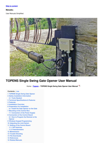
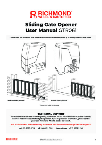
Sliding Gate OpenerUser Manual GTR061Please Note: This motor runs on AC Power as standard but can also be operated by DC Battery Backup or Solar Power.Gate in closed positionGate in open positionViewed from inside the propertyTECHNICAL SUPPORTInstructions must be read before beginning installation. Please follow these instructions carefully,incorrect installation could affect gate operation. If you require more information, please contactyour local Richmond Wheel & Castor Co branch.For installation or troubleshooting assistance visit richmondau.com/gate-motor-support/AU: 03 9070 5713NZ: 0800 61 71 81International: 613 9551 2233GTR061 Installation Manual: Rev 31
Optional Accessories Available:Additional Remotes (GTR179): Spare/Additional remotes for the automatic gate kit, these willneed to be paired to the motor.Remote External Receiver (GTR197): Allows more remotes to be paired to the motor. Pair upto 250 remotes with this accessory.Wireless Keypad (GTR180): Allows secure access through the gate used with a user set code.Wireless Push Button (GTR201): Allows access through the gate at the push of a button.Hard Wire Push Button (GTR202): Allows access through the gate at the push of a button.Reflective Photocells (GTR208): Increase safety during opening/closing by preventing gatesfrom closing on vehicles/pedestrians.Warning Light (GTR198): Alerts people near the gate and users that the gate is in operation.Solar and Battery Backup Packs Available: Solar panels and more available to get this gatekit running on solar power. Please contact your nearest authorised dealer for compatible solarpanels in your state/region.Please refer to the relevant manual for each accessory forinstructions on wiring them to the GTR061 gate motor.GTR061 Installation Manual: Rev 32
Contents:Gate Opening Default Setting Information4General Safety5Parts List6Technical Specifications7Motor InstallationBefore you start8Tools Required / Example Sliding Gate Setup9Step 1 – Gate Preparation10Step 2 – Motor Pad Footing11Step 3 - Motor Position Installation11Step 4 – Drilling Holes for Anchor Bolts12Step 5 – Fitting the Mounting Plate & Motor12Step 6 – Gear Rack & Motor Alignment13Step 7 – Limit Travel Stops15Step 8 – Powering the Motor17Step 9 – Testing the Limit Travel Stops18Programming and WiringControl Board Diagrams19Dip Switch Adjustment22Further Settings and Programming23Battery/Solar Connection26Connecting Battery Backup (sold separately)26Connecting Solar Power (sold separately)27Troubleshooting28Clearing and Pairing Remotes29Additional Drawings and Diagrams30Maintenance30For accessories: please refer to the relevant accessorymanuals for instructions on wiring them to the GTR061 motor.GTR061 Installation Manual: Rev 33
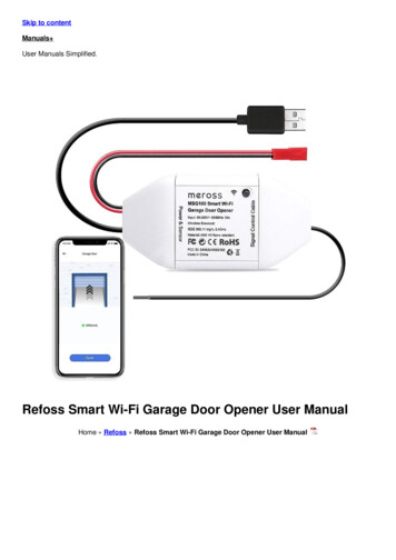
Gate Opening Default Setting Information:The gate motor will open the gate to the right-hand side as its default setting (refer to fig 1).It is recommended that you allow a minimum 500mm bottom rail extensionfrom your inside gate post opening. This will enable you to have enoughroom to secure your gear rack and placement for the motor.Default operation:Motor mounted onthe right-hand sideFig 1Before Installing: Test the motor by plugging it into a power source and pressing the remote. You will see the motorcog turn. When it stops (after approx 1 minute), press the remote again to see it turn in the opposite direction. This willgive you an understanding of the way in which the motor will move the gate.Press the first/top buttonon the remote.The motor cog will turn counter-clockwise,moving the gate frame.The gate will then move in the setdirection. Default: right-hand open.Note: Ensure that the motor is unplugged before proceeding with installation. Please keep fingers away from the motor cog whilst it is turning.If your gate needs to open from the other direction (to the left, refer to fig 2) your motor needs to be mounted on the left-hand side asshown below, you will need to switch DIP SWITCH 5 from OFF to ON (refer to page 22).It is recommended that you allow a minimum 500mm bottom rail extensionfrom your inside gate post opening. This will enable you to have enoughroom to secure your gear rack and placement for the motor.00mmMIN 5MImmN 500Left-Hand Opening:Motor mounted on theleft-hand sideFig 2Any works done to the motor must be completed whilst the power is off and the motor is unpluggedGTR061 Installation Manual: Rev 34
Thank you for choosing this sliding gate opener. Please read the manual carefully before assembling and usingthe opener. Do not leave out the manual if you send this product to a third party. This product complies with therecognised technical standards and safety regulations. Our company has the right to change this manual withoutprior notice.General Safety:Warning: Incorrect or improper use of this product can cause damage to persons,animals or properties. Warning: Incorrect or improper use of this product can cause damage to persons, animals or properties.Please ensure that the input voltage used matches with the supply voltage of gate opener (AC240V50Hz).All modifications to wiring or electrics, and any adjustment or maintenance to 240VAC MUST be done by aqualified electrician.To avoid damaging gas, power or other underground utility lines, contact the relevant authority BEFOREdigging.All potential hazards and exposed pinch points of the gate must be eliminated or guarded prior to installationof this gate motor.Never mount any device that operates the gate motor where the user can reach over, under, around orthrough the gate to operate the controls. These must be placed at least 1.8m from any moving part of themoving gate.Ensure power plug is disconnected from the power socket during installation or maintenance.Keep remote control and other control devices out of children’s reach, in order to avoid unintentionalactivation.Never allow anyone to hang onto the gate while moving.Please ensure a warning sign provided is fitted to the structure.To ensure safety, before installing the main motor, mount a Gate End Stop (GTR017) and a Gate Stopper(GTR017 or GTR018) at each end of the rail to prevent the gate travelling off the track.If required, install infrared photocells (GTR096, sold separately) to detect obstructions and prevent injury ordamage. Instruct all users about the control systems provided and the manual opening operation in case ofemergency. Ensure that the power cable is connected to a RCD protected weatherproof power outlet installed by aqualified electrician.Do not install the product in an explosive atmosphere or where there is any danger of flooding.This product was exclusively designed and manufactured for the use specified in the present documentation.Any other use not specified in this documentation could damage the product and be dangerous.Only use original parts for any maintenance or repair operation. Richmond Wheel & Castor Co declines allresponsibility with respect to the automation safety and correct operation when other supplier’s componentsare used.Do not modify the automation components, unless explicitly authorised by Richmond Wheel & Castor Co.The user must avoid any attempt to carry out any works or repairs on the motor, and should always requestthe assistance of qualified personnel.This motor is suitable for use on one sliding gate only.Anything which is not expressly provided for in these instructions is not allowed and will void warranty.Dispose of all packing materials (plastic, cardboard, polystyrene etc.) according to current guidelines. Keepplastic bags and polystyrene out of children’s reach.Please save these instructions for future use.GTR061 Installation Manual: Rev 35
Parts List:No.PictureNameQuantity1Main motor12Motor Mounting Plate13Manual release keys(These keys are needed during poweroutage, keep on hand)24Remote controls(factory paired to motor)25Gate Warning Signage(must be fitted to gate)16In the accessories box you will findthe items below:16aLimit travel stops(left hand & right hand)26bLimit switch mountingplate screws M6X1846cM12 x 100mm masonry anchor bolts(Drill bit size: M12 masonry)46dMotor mounting set screws M10 x50mm, spring & flat washers4GTR061 Installation Manual: Rev 36
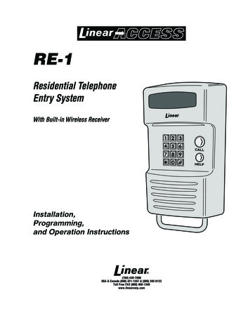
Technical Specifications:ModelGTR061Power supply240V/50HzMotor power170WGate moving speed16-18m/minMaximum weight of gate800 KgRemote control distanceUp to 30mRemote control modeSingle button modeLimit switchSpring limit switchNoiseUp to 58dBWorking dutyS2, 20min (20 minutes continuous operation)IP RatingIP54Maximum RemoteControls to be paired25Frequency433.92 MHzWorking temperature-20 C 70 CFig 03GTR061 Installation Manual: Rev 37
Motor Installation:Before you start The GTR061 Sliding Gate Motor is suitable for powering the opening and closing motion of gates up to800kg in weight, and up to a length of 8m on level, flat ground.Gate motion is achieved by the rotating cog of the gate motor driving the gear rack fitted to the movinggate (sold separately).The gate motor requires you to press the remote control once to open, and once again to close. This isa safety feature to ensure safe operation.The gate motor itself must be fitted within private property, never externally to a property’s boundary.This premium motor has a range of optional accessories which can be added, such as solar power,battery backup, infrared photocells, keypads, push buttons, and warning light. Power Supply: The GTR061 requires 1 x 10Amp AC240V 50Hz power supply (RCD ProtectedWeatherproof PowerPoint). The GTR061 comes complete with a power lead and plug that is 1m long. Ifyou do not have a suitable RCD protected weatherproof power point within 1m of the gate motor you willneed to consult a licenced electrician.Any works done to the motor must be completed whilst the power is off and the motor is unplugged.The gate motor will open the gate to the right-hand side as its default setting (refer to fig 1).Any modifications/alterations/works to the 240V AC power components must only be completed bya licensed electrician for your state/country.Please Note: Your weatherproof power outlet should be no more than 1m from the electric gate motor. If your weatherproof power outlet is more than 1m from the gate motor, you will require a licensed electrician to fit a new power cable. Any excess cable length should be cable tied and secured out of the way of moving objects.GTR061 Installation Manual: Rev 38
For Installing Your Gate Motor, You Will Need: Power drill Tape measure Level 12mm Masonry Drill Bit (for the 4 motor masonry anchor bolts) Socket and Spanner Set Phillips Head ScrewdriverExample Sliding Gate Setup:It is recommended that you allow aminimum 500mm bottom rail extensionfrom your inside gate post opening. This willenable you to have enough room to secureyour gear rack and placement for the motor.Gate Track andTrack WheelsGate EndCatchGate GuideRollersGateStopperIf you require any gate hardware, contact Richmond Wheel & Castor Co or an authorised reseller.GTR061 Installation Manual: Rev 39
Please ensure that the motor power cable is not plugged in at any stage before Step 8Step 1 - Gate Preparation Before AddingYour Sliding Gate Motor:1 Ensure that the sliding gate is correctly installed.2354The gate is horizontal and level and the gate can glide back and forth smoothlywhen moved by hand before installing the Automatic Gate Opener.Wheels and guide rollers should rotate easily and be free from dirt/grime.Track should be flat, level and firmly affixed.Any misalignment in the gate will affect performance of the automatic gate opener.6Suitable forInstallation235Gate4 on a flat, level surfaceCU76COMSALNAMSIGNAMEDRAWNPROPRIETARY AND CONFIDENTIALTHE INFORMATION CONTAINED IN THIS DRAWINGIS THE SOLE PROPERTY OFRichmond Wheel & Castor Co.ANY REPRODUCTION IN PART OR AS A WHOLE WITHOUTTHE WRITTEN PERMISSION OFRichmond Wheel & Castor Co.IS PROHIBITED.1234Gate on an incline/declineDATNot Suitablefor InstallationSIGNATUREDO GTOMTMQ.ADAVIDDPUNLESS OTHERWISE SPECIFIED:DIMENSIONS ARE IN MILLIMETERSTOLERANCES TO 0.25MMMATERTITLE:R12/02/2020DWG N12/02/2020GTRDEBUR ANDBREAK SHARPEDGESFILE LOCATION: \\Dataserver\sys4\db\dave\sketches\Gate parts\GTR156 set up\For installation on sloping surfaces contact Richmond to discuss a suitable motor optionGTR061 Installation Manual: Rev 310
Step 2 - Motor Pad Footing (Minimum Requirement): The motor pad concrete footing requires an area of no less than 450mm long x 300mmwide and a minimum depth of 200mm (Standard requirement).Ensure surface is level and parallel to the drivewayConcrete pad should be min 20-25MPA (Rapid Set Concrete not recommended)allow to cure for 7-10 days before drilling and securing the mounting plate into position.Mounting Plate Dimensions:Fig 4Step 3 - Motor Position Installation: Insert the key and open the manual release bar to put the motor into manual mode, and checkthat the motor cog rotates freely by hand (As per Fig 17). Place the motor and motor mounting plate on the concrete pad. Make sure the distance between the gate motor cog and gear rack position are aligned. Mark all four corners of the mounting plate on the concrete pad using a pencil, chalk or similar,to ensure the mounting plate is in the correct position before drilling. Remove motor from the mounting plate.When mounting and positioning the motor ensure that the power cable is unplugged. The motorcover will need to be removed to mount the motor to the mounting plate.Sliding Gate Frame (in open position)21-17mm53-57mmMarkcornersof themountingplate witha pencil,chalk, orsimilar.Fig 5Fig 6Once the gate has been placed onto the gate motor the gate must move backand forth freely at all times when in manual release modeGTR061 Installation Manual: Rev 311
Step 4 - Drilling Holes for Anchor Bolts: Mark the (4) positions for your anchor bolts ready for drilling (refer to Fig 7).Remove Mounting plate.Using a M12 masonry drill bit, drill holes to a minimum depth of 120mm (Fig 8).mm208135mmFig 7Fig 8Step 5 - Fitting Mounting Plate & Motor: Fit motor mounting plate back into place and fit and tighten anchor bolts (as per figures 9 and 10). Fit motor back on mounting plate, ensuring the power cord is positioned into the end slot of the mountingplate in the direction of the power point, making sure there are no pinch points (as per fig 11). Slide rubber grommet along the power lead and into the end slot of the mounting plate (as per figures 12 & 13). Bolt motor to the mounting plate using the M10 x 50mm bolts with spring and flat washers provided andtighten as required (as per figure 14).Tighten bolts usingspanner or socket setFig 9Fig 10Insert the M10 x 50mm bolts(Part 6d), spring washers,and flat washers providedthrough motor housing andscrew into welded nut on thebaseplate.Hand-tighten set screwsbefore final adjustment of motor.Fig 11Fig 12Fig 13Fig 14Once the gate has been placed onto the gate motor the gate must move back andforth freely at all times when in manual release modeGTR061 Installation Manual: Rev 312
Step 6 - Gear Rack & Motor Alignment: Insert the key and open the manual release bar to put the motor into manual mode,and check that the motor cog rotates freely by hand (as per fig 17).Ensure that the gate drive cog has a minimum clearance of 1-2mm along the entirelength of gear rack fitted to the gate (as per Fig 15)Ensure cog and rack are correctly aligned. Under no circumstances should the gatemotor drive cog carry any weight of the gate. It is the task of the gate castors orwheels to carry the weight of the gate. (As per Fig 16)If the gate doesn’t slide freely by hand, adjust gear racks height accordinglyuntil the full length of gate slides freely by handGear rack correctly aligned at 90 to the motor cogGear rack misaligned.Do not attempt to use if misaligned.Fig 15Fig 16At this stage of final assembly, the cover is removed (not shown) and the power cable is still unplugged.To put the gate motor into manual mode, insert thekey and open the manual release bar as shownIn manual mode, the gear can turn freelyand the gate can be operated by handFig 17GTR061 Installation Manual: Rev 313
At this stage of final assembly, the cover is removed (not shown) and the power cable is still unplugged.Fig 18GTR061 Installation Manual: Rev 314
Step 7 - Limit Travel Stops:Included in your gate motor kit are two limit travelstops (Part 7a) which must be fitted to the gearracks on your gate to ensure safe operation.The limit travel stops are designed to set thedesired opening and closing position of yourgate. These limit travel stops are designed tocome into contact with the spring limit switch.Please note: gates can open and close indifferent positions due to different weights ofgates, terrains, slopes (uphill or downhill). Thedistance the gate will travel after contacting thespring limit switch may vary.Instructions on setting the limit travelstops can be found on the next pageFig 19M6 x10mmM6 x10mmThe installation of spring limit switch block is shown in Figure 20Fig torThis diagramshows the gatein the openpositionMotorGearCogMountingPlateFig 21GTR061 Installation Manual: Rev 315
Setting the Limit Travel Stops:Closed Position: Position gate 150-200mm back fromthe gate end catch closed position.This will help in making sure you donot slam the gate into the end stop/catch when setting the closed positionunder power.Fit limit travel stop onto the top ofgear rack at the point where it meetsthe spring limit switch on the motor.Tighten locking screws.Fig 22Open Position: Position gate 150-200mm back fromthe gate stopper open position. Thiswill help in making sure you do notslam the gate into the end stop/catchwhen setting the open position underpower.Fit limit travel stop onto the top ofgear rack at the point where it meetsthe spring limit switch on the motor.Tighten locking screws.Fig 23Test the spring limit travel stops by moving the gate manually until you hear a click, making sure contact ismade with the spring limit switch on the motor.To Reset: When setting new limit travel stop positions please ensure that you turn the power off and then onagain. Turning the power off will reset the limit travel stop memory, allowing for new limit travel stop positions tobe recognised by the motor.Once satisfied the gate is opening and closing to the test limit switch position. Set the limit travel stop positionsin place (see Step 8 and Step 9 for instructions on powering the motor and testing the limit switch positions).GTR061 Installation Manual: Rev 316
Step 8 - Powering the Motor: Ensure that the outer cover has been fitted and fastened back onto the motor housing.Before powering up the motor make sure the gate can travel by hand in manual mode (key unlocked).Slide the gate to between the middle of the posts, approximately (see below diagrams).Lock the key (key locked) in readiness for automatic mode.Plug the power cord from the low voltage power supply into the power outlet.Remote controls (Part 4) included in this kit are factory paired ready for use.Please Note: The default setting is opening to the right.Press the remote control and the gate will open until the spring limit travel stop hits the spring limitswitch. Press the remote control again and the gate will close.Soft start/soft stop function - The GTR061 is set by default to provide the soft start/soft stop function.We recommend this default position is always maintained.Your motor is now set up for basic remote control operation. To set furtherfunctions and settings, see pages 19-27For accessories: please refer to the relevant accessorymanuals for instructions on wiring them to the GTR061 motor.GTR061 Installation Manual: Rev 317
Step 9 - Testing the Limit Travel Stops:Testing the closed position Ensure motor is plugged in as per step 8 and the gate is inthe open position. Press remote (remotes included in kit are factory paired to themotor). The gate will begin to close. The limit travel stop will hit the spring limit switch and the gatewill stop. When the gate stops, measure the distance remainingbetween the gate and the desired closed position. You have now determined the closed position of the gatewhen the travel limit stop hits the spring limit switch. Adjust the limit travel stop from the measurement you have taken toget your final gate closed position. The ideal closed final position forthe gate frame is 10-15mm from closed gate end catch (GTR019).Warning:Please allow space to ensure thegate does not impact against thegate catch or the end stop. See fig 24Testing the open position Press remote. The gate will begin to open. The limit travel stop will hit the spring limit switch and thegate will stop. When the gate stops, measure the distance remainingbetween the gate and the desired open position. You have now determined the open position of the gate whenthe travel limit stop hits the spring limit switch. Adjust the limit travel stops from the measurement you have takento get your final gate open position. The ideal open final position forthe gate frame is 10-15mm from the gate stopper (GTR017).Fig 24To Reset: When setting new limit travel stop positions please ensure that you turn the poweroff and then on again. Turning the power off will reset the limit travel stop memory, allowingfor new limit travel stop positions to be recognised by the motor.GTR061 Installation Manual: Rev 318
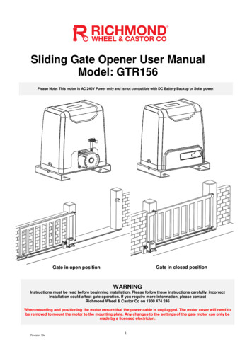
Programming and Wiring: Control Board Wiring Diagram 01Ensure power is off before any modifications are madeLearn ButtonPotentiometersDip SwitchesJ8 TerminalJ1 TerminalJ10 TerminalJ4 TerminalJ7 TerminalJ2 TerminalFuse holder24VDC BATTerminalRichmond FusePart Number:5GTR156SP002 Fig 25Generic Fuse PartNumber: F10AL250VSee next page formore details.Please refer to page 24 and 25 for added description of the terminalsGTR061 Installation Manual: Rev 319
Programming and Wiring: Control Board Wiring Diagram 02Ensure power is off before any modifications are madeLearn ButtonWarning LampCOMInfrared Sensor24VDC24VACMotorMOPENCOMCLOSEDCOMStop ButtonClose ButtonOpen Button 24VACFuse Details:StorageBatteryRichmond Part Number5GTR156SP002Generic Part NumberF10AL250V Fig 26Fuse TypeFuse SpeedAmpsVoltageLengthDiameterGlass Ferrule (3AG)Fast Acting10250vAC20mm6.35mmPlease refer to page 24 and 25 for added description of the terminalsGTR061 Installation Manual: Rev 320
Transformer Power Input Connection:WARNING: Do not touch 240V AC. All works to mainspower must be conducted by a licensed electricianF5AC250V Fuse(5mm dia x20mm long glasscartridge fuse)J2Fig 27GTR061 Installation Manual: Rev 321
Dip Switch Adjustment:NumberDescriptionAutomatic Close Function1 ON 2 OFF: automatic close delay time is 3s.1 OFF 2 ON: automatic close delay time is 10s.1 ON 2 ON: automatic close delay time is 30s.1 OFF 2 OFF: no automatic close function.Default position is 1 OFF 2 OFFRemote Control Modeleave in OFF position unless an additional module is used.Default position is OFFExternal Button ModeLeave in OFF position unless an additional module is used.Default position is OFF4 OFF: Hard wire keypadLeft/Right Open SettingOFF – Right hand openON – Left hand openGate close direction will be changed after motor is restartedDefault position is OFF (right hand)Spring Limit SwitchLeave in the OFF position,OFF - Normal closeON - Normal openDefault position is OFF (do not change)Stall ForceON - EnabledOFF - DisabledDefault position is ON (do not change)Infrared Detection Delay When ClosingON – Infrared detection delay is set to 1 secondOFF – Infrared detection delay is disabledDefault position is OFFGTR061 Installation Manual: Rev 322
Further Settings and Programming:VR1: Motor Running Time AdjustmentRotate clockwise to increase, counter-clockwise to decrease. Motor running time can be set to 10 secondsminimum, and 90 seconds maximum.The default setting is at maximum.VR2: UnusedVR3: Stall Force AdjustmentRotate clockwise to increase, counter-clockwise to decrease.The default setting is at midway.When stall force is enabled (DIP switch 7 is at the ON position), the motor will detect obstacles and impacts tothe gate. If this is during opening, the gate will stop, if this is during closing the gate will stop, and then re-open.When the motor detects any obstruction or impact during opening, the gate will stop and then return. Duringclosing the gate will simply stop when detecting any obstacle or impact.Rotate VR3 clockwise to increase the stall force, counter-clockwise to decrease. The factory default setting ismidway, for any dial adjustment required above this check your gate is free rolling with no resistance (capableof being moved freely by 1 person).For safety we strongly reccommend that stall force mode is left Enabled (dip switch 7 is at the onposition) do not switch dip switch 7 to the off postion.GTR061 Installation Manual: Rev 323
J1 Terminal:Terminal 5: Common (Ground).Terminal 6: Photocell input (Normally Closed). If no photocellis fitted use jumper between terminals 5 & 6.Terminal 7: Extra power input 24VDC.J7 Terminal:Terminal 1: Optional External Open Push Button Switch.(Hard Wired keypad connection between terminals 1 & 4)Terminal 2: Optional External Close Push Button Switch.Terminal 3: Optional External Stop Push Button Switch.Terminal 4: Common Terminal for All Optional Push Buttons.J10 Terminal:Limit Switch WiringOP: Open Circuit.COM: Limit Switch Common Terminal.CL: Closed Circuit.How to secure a wire to the circuit board terminalsEnsure that power is off before completing any wiringUsing a screwdriver, loosen the screwon the side of the terminal.insert the wire intothe terminalGTR061 Installation Manual: Rev 3Tighten with a screwdriver to secure thewire in place.24
J2 Terminal:Factory Fitted (pre-wired)Circuit board connection for low voltage power supply BAT Terminal:Battery Backup TerminalJ4 (MOT) Terminal:Factory Fitted (pre-wired)DC motor wire connection (Red wire to top,black wire to bottom).J8 Terminal:24V DC warning light connectionGTR061 Installation Manual: Rev 325
Battery Backup Connection:To operate this gate with battery backup you will needthe GTR206 Battery Backup Pack (sold separatelyBattery backup can be useful in areas where mainspower may be intermittent. Depending on the size andsetup of your gate, batteries may be able to operatethe gate up to ten times without being recharged.To install battery backup, refer to the Fig 28 below.Connect the pre-stripped black and redwires to the BAT terminal of the GTR061circuit board and then connect to yourGTR206 battery backup pack using the2-pin plug supplied.GTR206 batterybackup pack(sold separately)negative -positive GTR061ControlBoardBAT BAT Fig 28GTR061 Installation Manual: Rev 326
Solar Panel Connection:To operate this gate with battery backup you will need the GTR205 Solar Battery Pack and GTR049 SolarPanel (sold separately)Solar power is useful in areas where mains power is not readily available. The correct solar power and batterywill depend on the size and setup of your gate, position of the panels and geographical area.Note that performance may vary according the amount of sunlight per day, and condition of the batteries.To install solar power, refer to the Fig 29 below.GTR205 solarbattery pack(sold separately)GTR049 solar panel(sold separately)SolarLoad 24V DCGTR061ControlBoardnegative -positive Connect the prestripped black andred wires to the BATterminal of the GTR061circuit board, andthen connect to yourGTR205 solar batterypack using the 2-pinplug supplied.Lastly, connect the solarpanel to the batterypack using the 2-pinplug suppliedBAT BAT Fig 29GTR061 Installation Manual: Rev 327
Troubleshooting: Ensure power is off before any modifications are madeProblemsThe gate cannot openor close normally, andLED does not light.Possible ReasonsSolutions1.The power is off.2.Fuse is blown.3.Control PCB is damaged1.Switch on the power supply.2. Licensed electrician Check the fuse (F1)(refer to page 20 fig 26) and replace if necessary.3.Contact Richmond Wheel & Castor Co forreplacement PCB1. Remote control battery is flat.Remote control doesn’t2. Remote control is not paired correctly.work.1.Check LED lights up when button ispressed. If not, change the remote-controlbattery (A27 battery required)2. Repeat pairing procedure1. Photocell beam is interrupted.2. Stall force is set too low3. Photocell settings not correct.4. Photocell not mounted correctly.1. Check and remove any obstructions.2. Increase stall force VR3 potentiometer.3. If photocell is not connected, ensure thejumper wire is between 5 and 6 on the J1terminal, and dip switch 6 is set to ON. Ifphotocell is connected, remove jumper 5 and6 and ensure the wiring is correct and dipswitch 6 is set to OFF (N.C.).4. Make sure photocell beams are correctlypositioned.Gate does not movewhen button ispressed, but motormakes a noise.1. Gate is out of alignment.1. Connect in manual mode and check if itcan be opened by hand. If cannot be easilyopened, re-set up.2. Contact Richmond Wheel & Castor Co forreplacement PCB.Gate does not stop atthe limit switch whenopening/closing.1. Turn Dip switch 5 from ON or OFF (depending on its current setting)1.The gate direction is incorrect.2. refer to Pages 18 and 22.2. The limit switch is positioned incorrectly3. Check wiring for any damage. Contact3.The limit switch is damagedRichmond Wheel & Castor for a new limitswitch if required.The gate opens butcannot close.Current leakage switch1. Short circuit in the power supply line.tripped.1. Licensed electrician to check wiring.Remote controlworking distance istoo short.1.Signal is blocked or too muchinterference.1. Connect external receiverantenna 1.5 meters above ground.2. check remote control batteryGate does not fullyopen or close
Ensure that the sliding gate is correctly installed. The gate is horizontal and level and the gate can glide back and forth smoothly when moved by hand before installing the Automatic Gate Opener. A Wheels and guide rollers should rotate easily and be free from dirt/grime. Track should be flat, level and firmly affixed.