Transcription
Skip to contentManuals User Manuals Simplified.TOPENS Dual Swing Gate Opener User ManualHome » Topens » TOPENS Dual Swing Gate Opener User ManualDual Swing Gate OpenerUser’s ManualModel: PW 302/502/802TOPENS Websitehttp://www.topenstool.com/ Please read and follow all warnings, precautions, and instructions before installation and use. The gate opener could be powered by either the 24VDC AC-DC power supply which is included in the package or 2 PCS 12VDC batteries (connected inseries, at least 12AH, NOT INCLUDED) which can be charged by a solar panel. Never connect the solar panel to the control board directly to charge the battery. Periodic checks of the opener are required to ensure safe operation. Save this manual.
Ask for OPENS help by E-mail or phone anytime.Contents [ hide1 Safety Installation Information2 PW302 Parts List3 Tools Needed:4 Technical Specifications & Features5 Installation Overview6 Preparation for Installation7 Install the Gate Opener on the Gate8 Mounting of the Control Box9 Connection of the Power Supply10 How to Program the Remote to the Opener11 How to Erase All the Remote Codes12 How to Use the Remote to Operate Your GateOpener13 Wireless Keypad Programming14 Adjusting the Limit Switch15 Setting of the Control Board16 Maintenance17 File Downloads18 References19 Related ManualsSafety Installation Information1. READ and FOLLOW all instructions.2. The gate opener is intended for use with Class I vehicular swing gates. Class I denotes vehicular gate opener (or system) dwellings, or a garage orparking area associated therewith. Install the gate opener only when the opener is appropriate for the construction and the usage class of the gate.3. Gate opening system designers, installers, and users must take into account the possible hazards associated with each individual application. Improperlydesigned, installed or maintained systems can create risks for the ser as well as the bystander. Gate system design and installation must reduce publicexposure to potential hazards. All exposed pinch points must be eliminated or guarded.4. A gate opener can create high levels of force during normal operation. Therefore, safety features must be incorporated into every installation. Specificsafety features include safety sensors.5. The gate must be properly installed and work freely in both directions prior to the installation of the gate opener.6. The gate must be installed in a location so that enough clearance is provided between the gate and adjacent structure when opening and closing toreduce the risk of entrapment. Swinging gates shall not open into public access areas.7. The opener is intended for use only on gates used for vehicles. Pedestrians must be supplied with a separate access opening. The pedestrian accessopening shall be designed to promote pedestrian usage. The pedestrian access shall be located such that persons will not come in contact with themoving vehicular gate.8. Pedestrians should never cross the pathway of a moving gate. The gate opener is not acceptable for use on any pedestrian gate. Pedestrians must besupplied with separate pedestrian access.9. For an installation utilizing non-contact sensors (safety sensors), see the product manual on the placement of non-contact sensors (safety sensors) foreach type of application.a. Care shall be exercised to reduce the risk of nuisance tripping, such as when a vehicle trips the safety sensor while the gate isstill moving.b. One or more non-contact sensors (safety sensors) shall be located where the risk of entrapment of obstruction exists, such as the perimeter reachableby a moving gate or barrier.10. Never mount any device that operates the gate opener where the user can reach over, under, around, or through the gate to operate the controls.Controls are to be placed at least 6’ (1.8m) from any part of the moving gate.11. Controls intended to be used to reset an operator after 2 sequential activations of the entrapment protection device or de vices must be located in the lineof sight of the gate, or easily accessible controls shall have a security feature to prevent unauthorized use. Never allow anyone to hang on or ride the gateduring the entire travel of the gate.
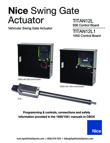
12. Each gate opener is provided with two safety warning placards. The placards are to be installed on the front and back of the gate where they are plainlyvisible. The placards may be mounted using cable ties through the four holes provided on each placard. All warning signs and placards must be installedwhere visible in the area of the gate.13. To AVOID damaging gas, power, or other underground utility lines, contact underground utility locating companies BEFORE digging. SAVEINSTRUCTION.14. Do not permit children to play on or around the gate and keep all controls out of their reach.PW302 Parts ListHardware
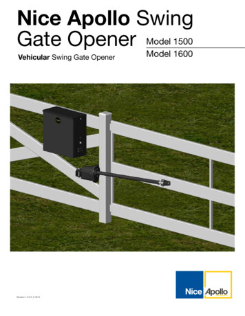
PW502/PW802 Parts ListHardwareAccessories Parts (Included in some models, refers to the actual package)
Optional Accessories Parts List (Available at TOPENS Store)Tools Needed:Power DrillTape MeasureOpen End Wrenches – 14# &17# or Adjustable WrenchesWire Strippers ·C-Clamps – small, medium, and largeLevelHacksaw or Heavy Duty Bolt CuttersPhillips Screwdriver ·An extra person will be helpfulTechnical Specifications & V 50/60HzMotor voltage:24VDCPower:2 30W2 50W2 80WCurrent:1.5A2A3AActuator speed:16mm/s 0.6 in/sMax. actuator travel:385mm 15.2 inAmbient Temperature:20 50 (-4 F to 122 F)Protection class:IP44
Features:Soft start and soft stopEmergency release key in case of power failureFast selecting push/pull to openStop in case of obstruction during gate opening.Reverse in case of obstruction during gate closing.Built-in adjustable auto-close (3-120 seconds)Built in max. Motor running time (MRT) for multiple safety protection (40 seconds)Reliable electromagnetism limit for easy adjustmentCan be equipped with a wide range of accessoriesAdjustable opening/closing interval between master and slave gateEasy to install, and minimum maintenance requirement
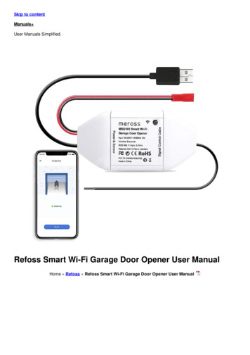
Installation OverviewPreparation for InstallationThere are two installation types for the gate opener, Pull-to-Open, and Push-to-Open.In the Push-to-Open installation, the gate opens out from the property. A Push-To-Open Bracket (PSO part) isrequired to be used for each gate.NOTE: Ensure the gate does not open into public areas.The gate opener is mounted to the gate and to the gate post. Both round and square posts can be used because the Post Brackets are curved. Whenmounting the Post Brackets, use bolts long enough to pass through the entire post. M10 x 200 bolts are included. Concrete anchors are not provided.When mounting the Post Brackets to wooden posts, a larger-size washer or metal plate should be used between the bolts and the wooden post to ensure thestability of the fastening hardware. If the post is smaller than 6″ diameter or square, it should be made of metal and set in cement to ensure its stability.Install the Gate Opener on the GateThe position of Post Bracket is very important. The following illustrations and tables are required to determine the proper mounting position for the PostBracket. The tables show the maximum opening angle of the gate for a given A and B. For example, if A is 15cm and B is 20cm, the maximum opening angle ofthe gate is 110 .Pull-to-Open Installation — Gate in Closed position (Moving-Rod is extended)
Push-to-Open Installation — Gate in Closed position (Moving-Rod is retracted)1. Insert the M10 x 30 bolt through the center hole of the post bracket and post pivot bracket as shown. Place a 10 washer , 10 lock washer and M10 nut onthe bottom of the bolt and hand tighten.2. Attach the gate bracket and post bracket assembly to the opener by inserting a clevis pin. Secure the clevis pins using the hairpin clips.
3. Open the release hole plug on the top of the gate opener, insert the release key, and turn the key 90 clockwise. This releases the motor and allows thepush-pull rod to be manually extended and retracted. To restore normal operation, turn the key 90 counterclockwise.4. With the opener fully retracted and with the gate in the fully open position (for Pull-to-Open installation) or fully closed position (for Push-toOpen installation), place the gate opener with the Post Bracket Assembly and Gate Bracket on the gate post and the gate. Position the Post BracketAssembly and Gate Bracket so that the gate opener is level.While holding the gate opener in the level position, temporarily secure it with two C-clamps.
5. Make sure that there is a minimum clearance of 2.5cm between the gate and the opener and that the operand the Post Pivot Bracket is not binding in boththe gate-open and gate-closed positions. If there is not at least 2.5cm of clearance or if the opener and the Post Pivot Bracket are binding, rotate the PostPivot Bracket and/or move the Post Bracket Assembly to obtain the minimum clearance and eliminate the binding. When the minimum clearance hasbeen obtained and any binding has been eliminated, place the M8 x 30 bolt through the aligned holes in the Post Bracket and the Post Pivot Bracket.6. Sign the bolt-hole point on the gate bracket and gate. Do this by placing a punch or a sign in the middle of each bolt slot on the post bracket assembliesand the gate bracket. It allows slight adjustments to the post bracket. Then remove the post bracket and gate bracket by taking off the C-clamps7. Drill 10.5 mm diameter holes through the post and the gate at the marked locations.
8. Attach the post bracket assemblies to the gate posts by inserting M10 x 200 bolts through each post bracket assembly and the drilled holes in the gatepost. Fasten each bolt with one 10 washer, one 10 lock washer, and one 10 nut.9. Attach the gate brackets to each gate by inserting two M10 x 75 bolts through the gate brackets and thedrilled holes in the gates. Fasten each bolt with one 10 lock washer and one 10 nut.10. Cut off any part of the bolts that extend beyond the tightened nuts.11. With the gate opener fully retracted and with the gate in the fully open position (for Pull-to-Open installation) or fully closed position (for Push-to-Openinstallation), attach the gate opener to the Post Bracket Assembly and the Gate Bracket by inserting a clevis pin through the gate opener and the PostPivot Bracket and another clevis pin through the gate opener and the Gate Bracket. Secure each clevis pin with a hairpin clip.12. Open the release hole plug on the top of the gate opener, insert the release key, and turn the key 90 counterclockwise. This restores normal operation.NOTE: The setting of the PULL/PUSH TO OPEN of the control board should be in accordance with the installation.
Mounting of the Control BoxUse 4 deck screws (not provided) to install the control box. Even though the control box is waterproof designed, for safety reason and a longer service life, it isrecommended to install the control box inside asecure surface and at least 100 cm (40 inches) above the ground to avoid being flooded or buried under snow.Connection of the Power SupplyThe gate opener could be powered by either the 24VDCAC-DC power supply which is included in the package or 2 PCS 12VDC batteries (connected in series, at least 12AH, NOT INCLUDED) which can be chargedby a solar panel. We recommend you to use the AC-DC power supply as the power source to save the cost if the AC electricity is accessible.Once if you choose the batteries as the power source, it’s no need to use the AC/DC power supplywhich is included in the package. You must purchase spare solar panel (at least 20W) and solar controller (24V, 10A with over-charge and over-dischargeprotection) to charge the batteries. Marine or Automotive Type Battery with a capacity greater than 12 AH is required (NOT INCLUDED). 2 PCS 12VDCbatteries can be connected in series to become 24VDC to power up the gate opener. The following diagram will show you how to connect 2 PCS batteries inseries. Please note the wire connection of them is very important. Incorrect wire connection will damage the control board. The batteries should be awaterproof type or you should place them in a waterproof housing.WARNING: NEVER connect the gate opener to the power outlet before all the installations have been done.1. Use the DPS180-U power supply as the power sourceThe positive output (RED wire) of the 24VDC power supply should be wired to the BAT (#11) terminal, and the negative output (YELLOW wire) should bewired to “BAT-” (#12) terminal.2. Use the batteries (Notincluded) as the power source and use the solar panel to charge the batteriesYou can choose the batteries to power up the gate opener if the AC electricity is not accessible. Please note youmust purchase a spare solar panel (at least 20W) and solar controller (24V, 10A with over-charge and over-discharge protection) to charge the batteries. Thegate opener can work for 10 cycles per day if there is no other accessory except photocell & electric lock & push button& Warning Light connected to thecontrol board if you use the 20W solar panel. The capacity of the batteries and the power of the solar panel should be enlarged if you want to use more times aday. You can connect the solar panel and the solar charge controller refers to the following illustration (e.g.: using TOPENS TSP solar panel & TCS3 solar
controller).Connection of the Control BoardAlmportant Note: This gate opener can be powered by either the 24VDC supplywhich is included in the package or 2 PCS 12VDC batteries (connected in series, at least 12AH. NOT INCLUDED) which can be charged by solar panel.Please connect the batteries& solar panel & solar controller refers to the chapter -Connection of Power Supply”1. Actuator 1 (Master gate, open first & close last)Insert the stripped cable wires into the appropriate terminals on the opener terminals block. The red wire should be inserted into the “ MOTOR1”terminal(#15), the black wire into “MOTOR1-” terminal (#16), the blue wire into “ULMT1” terminal(#17), the green wire into “ COM” terminal(#18), and theyellow wire into “DLMT1” terminal (#19).2. Actuator 2 (Slave gate, close first & open last)The red wire should be inserted into the “ MOTOR2” terminal(#20), the black wire into “MOTOR2-” terminal(#21), the blue wire into “ULMT2”terminal(#22), the green wire into “COM” terminal(#23), and the yellow wire into “DLMT2” terminal (#24).3. AC-DC power supplyPlease connect them refers to the chapter “Connection of the Power Supply”.4. Battery & Solar panel & Solar controller (Optional, Not included)Please connect them refers to the chapter “Connection of the power supply”.5. Warning Light (Included in some models, refers to the actual package)The red wire of the warning light should be inserted into either LAMP (#25) terminal, the white wire into the other one (#26).6. Photocell Beam System (PBS) (Included in some models, refers to the actual package)Use a 2-core cable to connect the “ ” terminal of the photocell’s emitter to the “ 24” (#1) terminal, the “- ” terminal to the “GND” (#3) terminal. Also the“ ” and “- ” terminals of the photocell’s receiver should be connected to the “ 24” and “GND” terminals in parallel.Use another 2-core cable to connect the “NC” terminal of the receiver to the “PHOTO” (#2) terminal, the “COM” terminal to the “GND” (#3) terminal.7. Push Button (optional)The push-button should be wired to the “#4 and “#5” terminals. No matter the polarity. The gate operator works alternately by pressing the button (openstop-close-stop-open).
8. Electric Lock (optional)A lock plus board is required to connect the electric lock to the control board. The 2 wires of J1 of lock plus should be wired to the “13#” and “14#”terminals of the control board. No matter the polarity. The red wire of J2 should be wired to the 11# terminal and yellow wire of J2 should be wired to the12# terminal. Red wire of J3 should be connected to the red wire of electric lock and also the yellow wire of J3 should be connected to the yellow wire ofelectric lock.NOTE: If you use the 24VDC AC-DC power supply as the power source and intend to use the electriclock, the open delay time of the 2 actuators should be more than 4S.9. Exit Wand (optional)The BLACK wire of the exit wand should be connected into the “#5” terminal.The BLUE wire of the exit wand should be connected into the “#6” terminal.The RED wire of the exit wand should be connected into the “#11” terminal.The GREEN wire of the exit wand should be connected into the “#12” terminal.The sensitivity adjustment board should be wired to the GREEN wire and the YELLOW wire of the wand. No matter the polarity.10. Wired Keypad (24VDC)(optional)The RED wire of the wired keypad should be connected into the “#11” terminal.The BLACK wire of the wired keypad should be connected into the “#5” terminal.The PURPLE wire of the wired keypad should be connected into the “#5” terminal.The BLUE wire of the wired keypad should be connected into the “#4” terminal.11. External receiver (optional)The RED wire of the external receiver should be connected into the “#11” terminal.The BLACK wire of the external receiver should be connected into the “#5” terminal.The BROWN wire of the external receiver should be connected into the “#4” terminal.Note: Using of the exit wand, keypad and external receiver would cause the battery to exhaust quickly. Big capacity of the battery and bigpower of solar panel (if the battery is used as power source) is required if you want to use either of them.How to Program the Remote to the OpenerThe remote MUST be programed to the opener BEFORE OPERATING. Please follow the steps to program the remote.Activate the opener only when gate is in full view, free of obstruction, and properly adjusted. No one should enter or leave gate area whilegate is in motion. DO NOT ALLOW CHILDREN to operate push button or remote. DO NOT ALLOW CHILDREN TO PLAY NEAR THE GATE.If you purchase additional remote controls, the gate opener must be programmed to accept the new remote code.If you lose one of any remote control, please erase and reprogram all other remote controls to have a new code for safety.Press and release the CODE SW button, the CODE LED will be ON, then press the key in the remote twice in 4 seconds, the CODE LED will flash for 3seconds and then to OFF. Now the remote has been programmed successfully.NOTE: Max. 8 remotes can be programmed for the opener. An External Receiver (optional) allows up to 250pcs remotes to be programmed for theopener. TOPENS ERM12 Universal External Receiver is available at TOPENS Store.TOPENS ERM12 Universal External Receiver is also compatible with other brand swing gate opener, sliding gate opener and garage door opener.How to Erase All the Remote CodesPress and hold the CODE SW button until the CODE LED from ON to OFF. Now all remote codes have been erased.How to Use the Remote to Operate Your Gate Opener
Each remote has four buttons, from top to bottom are separately A, B, C and D. You may use this remote to operate as many as 4 sets TOPENS swing gateopeners or 1 set TOPENS sliding gate opener and 2 sets TOPENS swing gate openers.1. Use this remote to only operate TOPENS swing gate opener A, B, C and D four buttons share same function once they are programmed with TOPENSswing gate opener. You may choose any button to program it with our swing gate opener. Every press of the button is able to active the gate opener towork alternately (open-stop-close-stop-open)2. Use one remote to operate TOPENS swing gate opener & sliding gate opener at the same time All of TOPENS sliding gate opener have midway mode.Button B is designed to realize midway function (refer to more details in our TOPENS sliding gate opener manual). So it is must program button A withsliding gate opener, while you may program either C button or D button with TOPENS swing gate opener.Wireless Keypad ProgrammingYou can follow the below steps to program wireless keypad to the opener. Press the CODE SW button until the CODE LED is ON, and then release the button.Then press “OK” button on keypad and CODE LED will flash for3 seconds and then be OFF which indicates the keypad has been programmed successfully.You can use the default password “888888” to operate the opener after programming. You can press “PIN” “8 8 8 8 8 8” and then press “OK” to confirm tooperate the opener.Also, you can change the password of the keypad follow the below steps. Press “PIN” and then input the six digits old password and then press ”PIN” again, theCODE LED will be ON. Input the six digits new password and then press the “PIN” to confirm the new setting, CODE LED will flash for 3 seconds and then beOFF which indicates the password has been changed successfully. You can press “PIN” “6 digits new password” and then press “OK” to confirm to operate theopener.NOTE: Every step for pressing button during program must be finished within 1 second to ensure successful programming.Adjusting the Limit SwitchAdjusting the Limit Switch of Actuator 1The position of Limit Switch A was fixed in factory, do not adjust it again.Plug on the power to running gateopener, use a screwdriver to loose the screw of Limit Switch B, slide Limit Switch B to the desired closed position and fix it. Limit setting for Gate 1 is finishednow.NOTE: Always place the magnetic ring between the Limit Switch A and B.Adjusting the Limit Switch of Actuator 2The position of Limit Switch C was fixed in factory, do not adjust it again. Use a screwdriver to loose the screw of Limit Switch D, slide Limit Switch D to thedesired closed position and fix it. Limit setting for Gate 2 is finished.
NOTE: Always place the magnetic ring between the Limit Switch C and D.NOTE: The magnetic ring in the moving rod can be manually placed between both Limit Switches in eachactuator by releasing the clutch.Setting of the Control BoardWARNING: Ensure the gate opener is Power Off when you make any adjustment of the gate opener. Keep away from the gate during you setthe gate opener system in case of the unexpected gate moving. Carefully adjust the DIP switches to avoid the risk of machine damage and injury ordeath. Always ask the help of a professional technician /electrician if you have any questions.1. DIP SwitchesThe DIP switches are used to select pull/push to open, enable/disable auto-close function, enable/disable open the interval between the master and slave gateopener, enable/disable close interval between the master and slave gate opener and enable/disable photo beam function.DIP Switch #1: Select push/pull to openIf the gate opens into the property (pull to open), the DIP Switch is set to OFF (factory default setting). If you gate opens out from the property ( push to open)the DIP Switch must be set to the ON position.Factory default setting is OFF.DIP Switch #2: Auto close function enabled/disabledON – Auto close function enabledOFF – Auto close function disabledSet the switch #2 to ON to enable the auto close function. Factory default setting is OFF.DIP Switch #3: Enable/disable open interval between the master and slave gate openerON – Open interval is enabledOFF –Open interval is disabledFactory default setting is ON.NOTE: Open interval time can be adjusted by the OPEN DELAY potentiometer.DIP Switch #4: Enable/disable close interval between the master and slave gate openerON – Close interval is enabledOFF –Close interval is disabledFactory default setting is ON.NOTE: Close interval time can be adjusted by the CLOSE DELAY potentiometer.DIP Switch #5: Photocell function enabled/disabledON – Photocell function enabledOFF – Photocell function disabledYou must set the switch #5 to ON to enable the photocell function if you want to use the photocell with the gate opener. Factory default setting is OFF.2. PotentiometersThere are 5 potentiometers located in the control board. They are used to adjust soft stop period, auto-close time, open interval and close interval time betweenmaster gate opener and slave gate opener, and the stall force.
Potentiometer A is used to adjust the soft stop period of the gate opener. Turn the potentiometer clockwise to increase the soft stop period, and turn itcounter-clockwise to decrease the soft stop period. The soft stop period can be adjusted steplessly from 1 to 5 seconds.Potentiometer B is used to adjust the auto-close time of the gate opener. Turn the potentiometer clockwise to increase the auto-close time, and turn it counterclockwise to decrease the auto-close time. The auto-close time can be adjusted steplessly from 3 to 120 seconds.Potentiometer C and potentiometer D are used to adjust the open interval and close interval time between the master gate opener and the slave gate openerrespectively. Turn the potentiometer clockwise to increase the interval time, and turn it counter-clockwise to decrease the interval time. The interval time can beadjusted steplessly from 1 to 9 seconds.Potentiometer E is used to adjust the stall force the gate opener. Turn the potentiometer clockwise to increase the stall force, and turn it counter-clockwise todecrease the stall force.MaintenanceWarning: Disconnect power before servicing.1. Using a clean, dry cloth to wipe the gate opener shaft, and then apply a silicone spray to reduce its friction. In cold climates where temperatures reach1 C (30 F) or less, spray silicone on the actuator every 4 6 weeks to prevent freeze up.2. Regularly check gate hinges to make sure gate is swinging smoothly and freely. Grease hinges if needed.3. Check your installation periodically, as hardware and posts will shift. Brackets may need to be adjusted or hardware may need to be tightened.4. Maintain the area around your gate. Keep the areas free of objects that can prevent the gate from swinging freelNOTES:1. Inspection and service should always be performed anytime a malfunction is observed or suspected.2. It is suggested that while at the site voltage readings be taken at the operator. Using a Digital Voltmeter, verify that the incoming voltage to the opener it iswithin ten percent of the opener’s rating.3. Refer to the instructions on how to check gate force and sensitivity adjustments.Status of gate openerStatus of LED(s)Possible Solution(s)StandbyCODE LEDPOWER LEDFULL LEDRunningOFFFlash(1 Blink everysecond)OFFNormal (Voltage of thebattery isnormal)StandbyFlash(1 Blink everysecond )Flash(1 Blink everysecond)Flash(1Blinkevery second)NormalBoth of the gates do not movewhen operatingOFFFlash(1 Blink everysecond)Normal ONNormal (Battery is full)
Both of the gates do not movewhen operatingOFFFlash quickly for3 seconds and then back OFFto OFF1. Make sure the remote has beenprogrammed to the control boardbefore using.2. The battery of the remote may beexhausted. Replace the battery andtry it again.3. The control board could be faulty.Replace the control board asnecessary.StandbyOFFFlash(1 Blink every 2seconds)OFF1. Check the power supply of the gateopener is connected or not.The batteries or a 24Vdc AC/DCpower supply must be used to powerthe gate opener.2. Check the fuse.3. Check if the wire connection of thepower supply is loosening or notThe gate reverse when on theway of opening or closingFlash(1 Blinkevery second )Flash quickly until thegate stop runningOFFVoltage of the battery is low, wait thebattery to be charged.Flash quickly for3 seconds and then backto flash slowly(1 BlinkFlash(1 Blinkevery second)every 2 seconds)Both of the gates donot movewhen operatingOFFBoth of the gates do not movewhen operatingFlash quickly forFlash quickly for3 seconds and then back3seconds and thenbackOFFto flash slowly(1 Blinkto OFFevery second)Both of the gates do not movewhenoperatingOFFFlash quickly forThe gate stop when on the way of10seconds and thenopening or closingback to OFF1. Ensure that the gates swing freelywithout any binding.2. The stall force is adjusted toosmall. Turn the Potentiometer Eto increase the force. 3. Ensure thephoto beamis not blocked whena photocell is used.Voltage of the battery islow, wait the battery to becharged.Flash quickly for3 seconds and then backFlash quickly for 3 secondsto flash slowly(1 Blinkand then back to OFFevery second)1. Ensure the photo beam is notblocked when a photocell is used. 2.Check if the photocell is defective ornot.Flash quickly for 10seconds and then backto flash slowly(1 Blinkevery second)Check if the jumper wire between theEDGE and GND terminal isloosening or not.OFF
The gate stop when on the way ofopening or closingOFFBoth of the gates do not movewhen operatingFlash quicklyOne gate runs normally butthe other one does not moveFlash(1 Blinkevery second )Flash quickly for10 seconds andthen back to flashslowly(1 Blinkevery second)Two sequential photo beam blockedFlash quickly for 10 seconds has been detected. Please ensure theand then back to OFFphoto beam is not blocked.Flash quicklyFlash quickly1. Two sequentialcontact entrapments havebeen detected. Please ensure there isno obstacle on the path of opening orclosing.2. Adjust the stall force bigger.Flash(1 Blinkevery second)Flash(1 Blink every second)1. Re-power on the gate opener.2. Replace the control board asnecessary.1. Exchange the wire connection ofthe 2 arms and check what willhappen to the 2 arms. If the faulty armis still faulty, then the arm itself isfaulty. If the failure changes to theother arm which worked normallybefore, then the control board is faulty.2. If the arm is confirmed faulty bystep 1, you can connect the RED &BLACK wire of the arm to the 24Vdcbattery to check if the arm could runnormally. If so, then the limit switchof the arm is faulty. If the arm still can’trun, then the motor part which isinside the arm is faulty.Gate automatically opens, butdoes not automatically closeFlash(1 Blinkevery second )Flash(1 Blinkeverysecond)Flash(1 Blink every second)Setting of DIP switch #1 could bewrong. Ple
A gate opener can create high levels of force during normal operation. Therefore, safety features must be incorporated into every installation. Specific safety features include safety sensors. 5. The gate must be properly installed and work freely in both directions prior to the installation of the gate opener.