Transcription
Rivier CollegeDepartment of Math and Computer ScienceFibre Channel TechnologyforStorage Area NetworksDavid NormanCS553A Introduction to Networking Technology02Dec2001
ContentsCONTENTS .2FIGURES .2INTRODUCTION.3The problem.3What is a Storage Area Network? .4What is Fibre Channel? .4Why use Fibre Channel for SAN? .4FIBRE CHANNEL TECHNOLOGY .5Introduction to Fibre Channel Technology .5The Fibre Channel Architecture.6Fibre Channel Equipment .15FIBRE CHANNEL AS APPLIED TO SAN .17Introduction to SAN.17Fibre Channel for SAN.17CONCLUSION .20BIBLIOGRAPHY .21FiguresFIGURE 1: TRADITIONAL STORAGE ARCHITECTURE WITH STORAGE DEVICES DIRECTLY ATTACHED TOSERVERS. .3FIGURE 2 : STORAGE AREA NETWORK ARCHITECTURE WITH STORAGE DEVICES ATTACHED TO SERVERSTHROUGH A NETWORK.4FIGURE 3: FIBRE CHANNEL IS DESIGNED FOR CHANNEL & NETWORK CONVERGENCE .5FIGURE 4: FIBRE CHANNEL TOPOLOGIES. .6FIGURE 5: FIBRE CHANNEL PROTOCOL ARCHITECTURE.7FIGURE 6: NOMENCLATURE FOR DESCRIBING FC-0 PLANT OPTIONS. .8FIGURE 7: EXAMPLE: REPRESENT A BYTE WITH TC NOMENCLATURE THEN CONVERT TO ITS 10 BIT ENCODEDVALUE. .9FIGURE 8: FRAME AND FRAME HEADER FORMATS. .10FIGURE 9: FRAME HEADER FIELD DESCRIPTIONS.11FIGURE 10: CLASS 1 DATA FLOW. NOTE R RDY ON CONNECT REQUEST ONLY.12FIGURE 11: CLASS 2 DATA FLOW. NOTE THE ACK FOR EVERY FRAME. ALSO R RDY.13FIGURE 12: CLASS 3 DATA FLOW. NOTE THE LACK OF ACK. ONLY R RDY FOR LINK MAINTENANCE. .13FIGURE 13: CASCADED ARBITRATED LOOP HUBS. .18FIGURE 14: A SIMPLE SWITCHED FABRIC TOPOLOGY.192
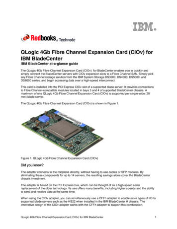
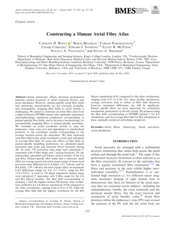
IntroductionThe problem.Today’s applications are rapidly overwhelming the capacity of networks and of storage space. In ecommerce, huge databases support electronic cataloging and ordering while large numbers of customersattempt to simultaneously access the information. As corporations grow and enter the internationalbusiness environment, enterprise systems maintain corporate information across not only states butcountries. To maintain and make available to all users that large amount of information reliably and in atimely manner is challenging to say the least. More and more feature films are incorporating digital effects.Video editing software, Computer Aided Drafting and photo-realistic rendering software are utilized toeither modify a film or even create one from scratch. Even a few seconds worth of a film requires hundredsof megabytes of storage space. When teams of 20 animators/digital artists are trying to work on their ownpiece of a film, the burden on the storage and the network facilities are tremendous. Web sites that serve upstreaming audio and or video are consuming more resources as the demand for these services go up. Inaddition to simply supporting bandwidth and storage increases, corporations now want to be able tosafeguard their data. This typically entails making backups of data (to tape) and saving data off thecorporate premises. This is an extremely small sample of the applications that are challenging the storageand networking architectures.Traditionally, these applications have been supported by file servers with either large internal disks or diskfarms directly attached to the server The disks are typically connected to the server via SCSI (SmallComputer System Interconnect). The SCSI standard defines a high throughput parallel interface that isused to connect up to 7 peripherals (including the host adapter card itself) to the computer. Examples ofthese peripherals are scanners, CD (Compact Disk) players/recorders, digitizers, tape drives and aspreviously stated hard disks. This architecture has several limitations. The server can only access data ondevices directly attached to it.If a server or any part of itsSCSI hardware fails, accessto its data is cut off. Also,. . .SCSI supports a finitenumber of devices, thereforeClientClientClientthe amount of data a servercan access is limited. If morestorage space is needed, butNetworkthere is no more room on theSCSI bus, expansion is nolonger possible. SCSI, due toits parallel structure, hasdistance limitations as well.This requires that the storageServerStorageServerStoragebe near the servers. Theselimitations are the drivingforce behind a new paradigmfor data storage and access.Figure 1: Traditional storage architecture with storage devicesdirectly attached to servers.3
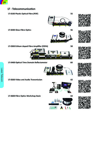
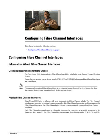
What is a Storage Area Network?Enter the Storage AreaNetwork (SAN). A SAN isconsists of a network that sits. . .between the servers and thestorage devices. Contrast thisClientClientClientwith the traditionalarchitecture of direct attachedLANstorage and you canimmediately see thedifference. A SAN allowsmultiple servers to access anystorage device. This helps toincrease fault tolerance. If aServerServerparticular server goes down,SANit does not take down a blockof storage. A SAN hasStoragegreater range than SCSI, thatis, the storage devices do notneed to be co-located withStorageStoragethe servers. This is attributedto the architecture of theFigure 2 : Storage Area Network architecture with storagenetwork that sits between thedevices attached to servers through a network.servers and the storage. Thepredominant technology usedto implement SANs is Fibre Channel.What is Fibre Channel?Fibre Channel (FC) is a high speed serial interface for connecting computers and storage systems. FC is amature technology having been approved and continually moderated by the American National StandardsInstitute (ANSI) T11X3 committee. New additions to the Fibre Channel specifications are continuallybeing added. There is strong industry support for Fibre Channel products. Vendors such as McData, Vixel,Emulex, Qlogic and StorageTek develop Host Bus Adapters, FC-AL Hubs, Fabrics and managementsoftware. They work together with solution providers such as Compaq, Dell, HP, IBM and Sun to createentire solutions.Why use Fibre Channel for SAN?Fibre Channel is the predominant technology for implementing SANs today because it does the best job atmeeting the requirements of today’s applications. FC is fast, currently it supports speed of up to 1Gbpswith 2, 4 & 10Gbps in the works. FC, being a network architecture, allows storage devices to be accessedby all servers on the SAN thus improving reliability. It supports several different topologies. Thetopologies have varying levels of cost to capabilities tradeoffs, thus allowing corporations to start with asmall, reliable setup and scale up as needed. It also supports distances up to 10mi via fiber optic cable. Thissupports the capability of off-site data storage for disaster recovery and high speed local area networkingbetween buildings on a campus or in the vicinity. Fibre Channel is a proven and fielded technology withmany companies manufacturing FC components for SANs.4
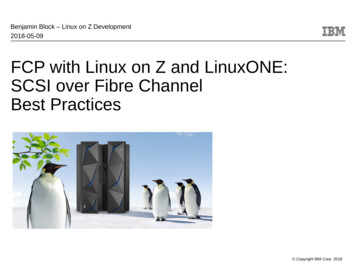
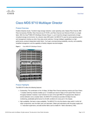
Fibre Channel TechnologyIntroduction to Fibre Channel TechnologyFibre Channel technology is a networking technology which is designed to facilitate high speed datatransfer between computer systems and storage devices. It supports several common transport protocolsincluding IP and SCSI. The support for multiple protocols allows FC to merge high-speed I/O withnetworking functionality in a single package. To understand FC, we must discuss the concept of a networkversus a channel.Many networks currently in use are connectionless. Data along with addressing information are bundledinto packets and transmitted over a shared medium. This methodology is relatively straight forward toimplement and works relatively well. These networks are flexible and can handle both changes inconfiguration and also varying load. However, it requires a large amount of overhead to get the packets togo to the proper destination with some level of reliability. Reliability is a major concern as evidenced bythe current concentration of work in the Quality Of Service (QoS) area. Also, as more users are added tothe network and the resources are used up, the timeliness and reliability of correct packet delivery goesdown.The concerns that apply to networking are not exactly the same as the concerns that apply to hardware I/O.Specifically the kind of I/O involved with storage devices but also with network hardware as well. Theprimary concern here is performance. This is where the concept of a channel is appropriate. An I/Ochannel’s purpose is to move data from one end of the link to the other with the least latency. Therefore, anI/O channel is typically hardware intensive with minimal software overhead. The tradeoff here is minimalerror correction. In order to achieve this level of performance, channels operate in a very clearly defineddomain. Reliability is achieved by minimizing errors by utilizing a rigorous and simple protocol.Therefore, channels are not as flexible in configuration as networks.Fibre Channel is designed to combine the best features of both networks and channels. FC maintains thespeed and low overhead of a channel while adding the flexibility (through connectivity) and the longerdistances that are characteristic of a network.ChannelsNetworks HW Intensive High Speed Low Latency Short Distance Bullet Proof Elementary ErrorCorrection SW Intensive Great Connectivity Higher Latency Long Distance Fragile High Overhead ErrorCorrection HW Intensive High Data Rates Low Latency No Station Management Great Connectivity Long DistanceChannel & Network ConvergenceFigure 3: Fibre Channel is designed for Channel & Network Convergence5
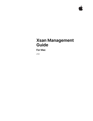
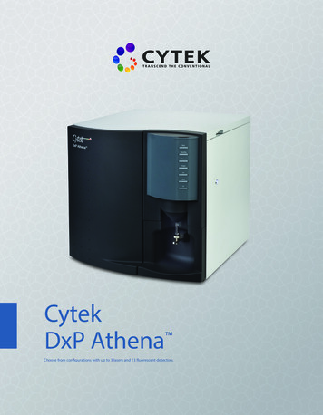
FC incorporates channel type features such as point-to-point dedicated connections and hardware intensiveprocessing for buffer control, error handling and encoding/decoding. FC incorporates networking typefeatures such as circuit and packet switching and use of data structures to pass control information in thedata stream. Other features include full-duplex transmission, support for both optical and copper as atransport medium and the ability to serve as a transport for other protocols, both channel and network.The Fibre Channel Architecture.The generic Fibre Channel network is composed of one or more bi-directional point-to-point channels. Thelinks support 1Gbps (or 100MBps) data rates in each direction. The transport media may be fiber opticcable, copper twisted pair or coax cable. The links in the FC network are between communication portsknown as N ports. N port stands for Node Port where a node is a device on the FC network. The linksmay be point-to-point between N ports or the may be set up as a Fabric. A Fabric consists of severalN Ports connected to a switch. Note: Ports on the switch are called F ports. Finally, the ports may be“daisy chained” to form a ring. This is called an Arbitrated Loop (FC-AL). In this configuration the portsare referred to as L ports. No switch is necessary for FC-AL. These basic layouts may be combined indifferent ways to create more complex topologies.FC is typically realized in one of 3 topologies: Point-To-Point, Loop or Fabric. The Point-To-Pointconnection is the simplest type of connection. It can exist by itself or as a subset in a Fabric or Looptopology. An example of a point-to-point topology would be a FC tape unit connected directly to a ge Subsystem(disk, tape, optical)Shared )ClusteringFigure 4: Fibre Channel Topologies.The Arbitrated Loop (FC-AL) topology in its basic form is when L ports are connected together. Theprimary advantages are that Loops are easy to setup and maintain and are relatively inexpensive.Additionally, several Loops may be connected via switch to share the load. Disadvantages inherent in aLoop are that Devices on a Loop must share the full bandwidth. The more devices, the less bandwidth isavailable to each. Also, they are subject to a failure similar to a series circuit. If one node on the loop goes6
down, the entire loop is out. A means of mitigating the effect of a node taking out the entire loop is the useof a FC-AL hub. Circuitry in the hub allows bypassing of failed nodes. An extra side benefit of the hub isthat it simplifies wiring. All the wires come into a central point instead of going from node to node.The Fabric topology, in some ways can be considered the “ideal” FC topology. The Fabric was originallydesigned to be a generic interface between each node and the physical layer. In theory, it would not matterto the N port whether it was connected to a loop, hub, switch or a storage device. It would simply work. Incurrent context however, the definition of Fabric has come to mean actual FC switch hardware.Advantages of Fabric topology are high performance, excellent connectivity and redundancy. Also, severaldifferent media types may be tied together with a Fabric. On the other hand, Fabrics are relatively costlyand configuring and maintaining them is not a simple task.Fibre Channel uses a multi layer protocol architecture along the lines of the 7 Layer OSI Model. There are5 layers. They are FC-0: Physical layer, FC-1: Encode/Decode layer, FC-2: Framing Protocol/FlowControl, FC-3: Common Services and FC-4: Upper Level Protocol Support. Additionally, there is anotherlayer, which although is not typically considered part of the basic architecture is so important as to warrantmention. This is the FC-AL (Arbitrated Loop) layer.F C -4H iP P IF C -3IPATMC o m m o n S e rv ic esF C -2F ra m in g P ro to c o l/F lo w C o n tro lF C -1F C -0SCSIE n c o d e /D e c o d e133 M bps266 M bps531 M bps1062 M bpsFigure 5: Fibre Channel Protocol Architecture.FC-0 LayerThe FC-0 level describes the physical interface. The purpose of the physical interface is to take a stream ofbits in at the transmitter, send them over the media, receive them and convert them back to bits at theoutput. Essentially, the physical interface represents a point to point link between two ports. It describesthe requirements for the transmitter, the transport media and the receiver hardware. Layer 0 also describesthe data rates that are supported by the different media types.The FC-0 layer has an analog interface to the transmission medium and a digital interface to the FC-1layer. The receiver must always be in an operational state but the transmitter may be on or off for severalreasons. One of the safety features of the optical implementation requires the transmitter to stoptransmitting if a fiber optic cable is disconnected or broken. This is to prevent any chance of the laser fromcausing eye damage. The transmitter is responsible for generating the transmission clock. Since the clock isencoded in the data stream, the receiver must be able to decode it. Also, the receiver includes a mechanismto detect the Special Character code known as the “comma” which is used for bye and word alignment.7
Speed400 - 400 MBps “Quadruple speed”200 - 200 MBps “Double speed”100 - 100 MBps “Full speed”50 - 50 MBps “Half speed”25 - 25 MBps “Quarter speed”12 - 12 MBps “Eighth speed”DistanceL - longI - intermediateS - short(actual distances aretechnology dependent)100-SM-LL-LMediaSM - single mode fiberM5 - multimode 50 umM6 - multimode 62.5 umTV - video cableMI - miniature coax cableTP - twisted pairTransmitterLL - long wave laser (1,300 nm)SL - short wave laser (780 nm)LE - long wave LEDEL - electricalFigure 6: Nomenclature for describing FC-0 plant options.FC-1 LayerThe FC-1 level describes the means by which user data is encoded for transmission and decoded at theother end. FC uses an 8/10 bit encode/decode scheme originally developed by IBM. This codeaccomplishes several things. It attempts to minimize errors by equalizing the number of 1’s and 0’stransmitted and not allowing more than 5 consecutive bits of the same type in a row. The code also allowsfor distinguishing “Special Characters” and also provides for simplifying byte and word alignment.Additionally, the evening out of 1’s and 0’s also has the effect of minimizing low frequency components inthe transmitted signal. This allows for the design of relatively inexpensive transmitter/receiver circuitrywhich can perform at the required bit error rate (10-12).All data transmitted through a Fibre Channel network are sent as 10 bit chunks known as TransmissionCharacters. The 8/10 bit code used in encoding data for transmission over an FC link is a very powerfultechnique. 8 bits of user data at a time are translated to a 10 bit word. The encoding scheme ensures thatthe resulting word has no more than 6 total of one type (either 1 or 0) and that no more than 4 of any onetype appear in a row. There is a special case where there are 2 characters of one type followed by 5characters of the opposite type known as the “comma”. This feature is important when looking at thecharacteristic of the transmitted signal. If there are many 1’s, for example, this would appear as a DCvoltage. This would make it extremely difficult for the receiver to know where bit boundaries are. If thereceiver can’t synchronize with the bit stream, it cannot pull the clock from the data stream. If it can’tdetect the clock, then it will never be able to use the data stream. This feature is the basis for keeping trackof the Running Disparity.A TC is composed of a 6 bit subgroup and a 4 bit subgroup. The running disparity is computed on a persubgroup basis and can be positive, negative or even. Positive is when there are more 1s than 0s in asubgroup. Negative is more 0s than ones than 0s. Even is when there are equal amounts of each. For eachTC, there is a corresponding value it may be encoded into for both positive and negative runningdisparities. The transmitter keeps track of the previous running disparity and will choose the appropriateencoding for the TC based upon keeping the running disparity as close to equal as possible. For example, ifthe previous disparity was negative, the encoding logic would encode the TC using its positive value.Transmission Characters (TC) come in two flavors, Data Characters (DC) and so called Special Characters(SC). Data characters consist of user data encoded into TCs via the 8/10 bit encoding scheme. SCs, usedfor control, are distinguished from DCs via a special indicator known as the control variable. The notation8
format of a TC is Zxx.y where Z is the control variable, xx is the decimal value of the binary numbercomposed of the bits E, D, C, B and A. The y is composed of the remaining 3 bits, H, G and F. Note: theorder is important when doing the converting. For all 256 data values, the encoding scheme produces validTCs, that is, they meet the qualification of having the proper ratio of 1s to 0s. Of the SCs, only 12 meet thatcriteria and of the 12, only one is currently used. That is the K28.5 also known as the “comma”. Once theTC has been transformed to the Zxx.y format, the Z, xx and y components are used to “look up” theircorresponding encoded bit patterns. The following example show the conversion process for the SC K28.5.The process is exactly the same for a DC except that a different set of tables are used for the encoding (thisis the purpose of the Z variable).FC-2 byte notation:0xBCFC-2 bit notation:------------76541011FC-1 un-encoded:--------HGF101FC-1 Reordered forZxx.y notation:ZZKYields the TC:K28.5-- Special ----HGF101To get the encoded version, look up K28 in the 5B/6B encoding table forSCs and look up .5 in the 3B/4B encoding table for SCs. At this point,the hardware would use the running disparity to determine whether toselect the positive or negative version. For this example, we will saythat the previous disparity was positive.FC-1 encoded:5B/6B (negative)--------------------abcdei0011113B/4B (positive)------------fghj1010Figure 7: Example: Represent a byte with TC nomenclature then convert to its 10 bit encoded value.Detection of valid characters actually begins in FC-0 where the hardware detects an incoming K28.5(comma) SC. This character only appears at the beginning of an Ordered Set which is aligned onTransmission Word (TW) boundaries. A TW is a set of 4 TCs. After this character is received, the receivercan now derive byte and word order and is able to decode TCs.Ordered Sets allow the FC-1 level to distinguish data from control information. The type of controlinformation is designated by the 3 TCs directly following a K28.5. Currently, there are 3 types of OrderedSets: Frame Delimiters, Primitive Signals and Primitive Sequences. Frame delimiters mark the beginningand end of frames and are used to specify the class of connection as well. Primitive Signals are used toindicate the Idle condition (maintain link when no data is flowing) and Receiver Ready (low level flowcontrol). There are also special events used with the Arbitrated Loop topology only. Primitive Sequencesrelay the state of FC ports such as Not Operational, Offline, Link Reset and Link Response. As withPrimitive Signals, there is also a set of sequences reserved for use with the Arbitrated Loop topology.9
Error detection at the FC-1 layer occurs during decoding. There are two types of errors that can occur. Thefirst is when 10 bits cannot be found in the encoding tables. This results in an invalid TC and a “codeviolation” is logged. The second type of error is when a valid TC is received, yet it was not the TC that wastransmitted. This type of error occurs when due to an error in the transmission hardware, a bit or bits getsflipped resulting in a valid TC, but when the running disparity is computed, it is not the expected value (forexample negative following negative instead of negative following positive).FC-2 LayerThe FC-2 level is, by far, the most complex layer of the protocol. The major elements of FC-2 are theencapsulation of data using frames, flow control and classes of service. Additionally, FC-2 provides errorcontrol. In order to serve as a transport mechanism, FC must be able to encapsulate user data and deliver itto the intended recipient. Frames are the basic package used to encapsulate and transport the data.Generally speaking, there are two basic types of frames, the Data Frame and the Link Control Frame. Bothtypes have the same basic format. A frame is composed of 6 basic sections.StartofFrameData Field - 2112 bytesFrameHeaderOptional24 bytes Header4 bytes64 bytesR CTLD IDreservedS IDTYPEF CTLSEQ IDPayload - 2048 bytesDF CTLOX IDSEQ CNTRX IDParameterCRCErrorCheckEndofFrame4 bytes4 bytesFrame Header fields:R CTL: Routing ControlD ID: Destination IdentifierS ID: Source IdentifierTYPE: Data structure typeF CTL: Frame ControlSEQ ID: Sequence IdentifierDF CTL: Opt. headers in data fieldSEQ CNT: Sequence countOX ID: Originator Exchange IDRX ID: Responder Exchange IDParameter: Frame type dependentFigure 8: Frame and Frame Header formats.The first section is the Start of Frame (SOF). The SOF is comprised of 4 bytes, the “comma” and 3 bytesindicating the type of connection service. Next is the Frame Header (FH). The FH contains information tocontrol link operations, perform routing, do protocol processing and detect missing or out of order Frames.One of the major functions of the FH is to uniquely identify active Frames. A Frame is uniquely identifiedby a combination of the following fields: S ID, D ID, OX ID RX ID, SEQ ID and SEQ CNT. ASequence Qualifier identifies active and open Sequences. The Sequence Qualifier is composed of all thefields listed above except the SEQ CNT. The SEQ CNT is used to identify the Frame’s location within theSequence. The Optional Header section can contain up to 4 types of headers. These are 1) ExpirationSecurity Header (how long until Frame should be discarded), 2) Network Header (contains info pertainingto network related ULPs e.g. IP), 3) Association Header (associates Frames with different Exchange Id’s)and 4) Device Header (contains other ULP info e.g. SCSI). Next comes the Payload. For a Data Frame, thepayload contains the user Data. For a Link Control Frame, the payload is not used. The CRC field is usedto verify the data integrity of the FH and Payload. Finally, the End of Frame (EOF) delimiter is an ordered10
set that designates the end of the Frame content. Additionally, the EOF contains information about thevalidity of the Frame’s content, whether to keep the connection open or normally close and if necessary,abort the connection.R CTL:D ID:S ID:TYPE:F CTL:SEQ ID:DF CTL:SEQ CNT:OX ID:RX ID:Parameter:Routing Control - used for categorizing the Frame’s functionDestination Identifier - address identifier of the Frame’s destination portSource Identifier - address identifier of the Frame’s source portData structure type - categorization of the Frame’s dataFrame Control - control information on Frame handlingSequence Identifier - unique identifier for the Frame’s SequenceOpt. headers in data field - indication of optional header inclusionSequence count - number of the Frame within its Sequence or ExchangeOriginator Exchange ID - identification of Frame’s Exchange at OriginatorResponder Exchange ID - identification of Frame’s Exchange at ResponderRelative offset (applicable to Data Frame) -OR- Frame information (applicable to LinkControl Frame)Figure 9: Frame Header field descriptions.One logical level up from the Frame is the Sequence. Sequences provide the means for ensuring dataintegrity of blocks of data that are transmitted and received. A Sequence is composed of a group of relatedFrames transmitted in one direction. As noted in previous sections, there are several other functionsperformed by the Start of Frame and End of Frame Ordered Sets. One of these additional functions is toinitiate and terminate Sequences. Other information pertaining to the control of Sequences is found indedicated fields in the Frame Header. Exchanges are groups of related Sequences. Exchanges are used toprovide a means for reliably sending Sequences. They do this by detecting and recovering from Sequenceerrors.Before data is sent across an FC Link, the N port performs Login procedures. Before a port connects to aFabric or another port, it is initialized with a default set of operating parameters. These are not typicallyoptimal. The login procedures allow the port to determine what type of environment it resides in and toadjust its operating parameters based on what it finds out. There are login procedures for Fabrics and forother ports. Logging into the Fabric lets the requesting port know 1) what type of topology it is connectedto 2) if attached to a Fabric, validates the requesting port’s port identifier and 3) if attached to a Fabric,provides the Fabric’s current operating parameters and buffer credit value (for flow control) to therequesting port. Logging into another N port lets the requesting port know 1) the port’s current operatingparameters and 2) initializes the end-to-end credit value and if Point to Point buffer-to-buffer credit value(for flow control). When a port logs
What is a Storage Area Network? Enter the Storage Area Network (SAN). A SAN is consists of a network that sits between the servers and the storage devices. Contrast this with the traditional architecture of direct attached storage and you can immediately see the difference. A SAN allows multiple servers to access any storage device. This helps to