Transcription
Configuring Fibre Channel InterfacesThis chapter contains the following sections: Configuring Fibre Channel Interfaces, page 1Configuring Fibre Channel InterfacesInformation About Fibre Channel InterfacesLicensing Requirements for Fibre ChannelOn Cisco Nexus 5000 Series switches, Fibre Channel capability is included in the Storage Protocol Serviceslicense.Ensure that you have the correct license installed (N5010SS or N5020SS) before using Fibre Channel interfacesand capabilities.NoteYou can configure virtual Fibre Channel interfaces without a Storage Protocol Services license, but theseinterfaces will not become operational until the license is activated.Physical Fibre Channel InterfacesCisco Nexus 5000 Series switches provide up to sixteen physical Fibre Channel uplinks. The Fibre Channelinterfaces are supported on optional expansion modules. The Fibre Channel expansion module contains eightFibre Channel interfaces. The Fibre Channel plus Ethernet expansion module contains four Fibre Channelinterfaces.Each Fibre Channel port can be used as a downlink (connected to a server) or as an uplink (connected to thedata center SAN network). The Fibre Channel interfaces support the following modes: F, NP, E, TE, and SD.Cisco Nexus 5000 Series Switch CLI Software Configuration GuideOL-16597-011
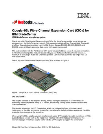
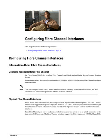
Configuring Fibre Channel InterfacesVirtual Fibre Channel InterfacesVirtual Fibre Channel InterfacesFibre Channel over Ethernet (FCoE) encapsulation allows a physical Ethernet cable to simultaneously carryFibre Channel and Ethernet traffic. In Cisco Nexus 5000 Series switches, an FCoE-capable physical Ethernetinterface can carry traffic for one virtual Fibre Channel interface.Native Fibre Channel and virtual Fibre Channel interfaces are configured using the same CLI commands.Virtual Fibre Channel interfaces support only F mode, and offer a subset of the features that are supported onnative Fibre Channel interfaces.The following capabilities are not supported for virtual Fibre Channel interfaces: SAN port channels. VSAN trunking. The virtual Fibre Channel is associated with one VSAN. The SPAN destination cannot be a virtual Fibre Channel interface. Buffer-to-buffer credits. Exchange link parameters (ELP), or Fabric Shortest Path First (FSPF) protocol. Configuration of physical attributes (speed, rate, mode, transmitter information, MTU size). Port tracking.Interface ModesEach physical Fibre Channel interface in a switch may operate in one of several port modes: E mode, TEmode, F mode, and SD mode (see the figure below). A physical Fibre Channel interface can be configuredas an E port, an F port, or an SD port. Interfaces may also be configured in Auto mode; the port type isdetermined during interface initialization.In NPV mode, Fibre Channel interfaces may operate in NP mode, F mode or SD mode.Virtual Fibre Channel interfaces can only be configured in F mode.Figure 1: Switch Port ModesCisco Nexus 5000 Series Switch CLI Software Configuration Guide2OL-16597-01
Configuring Fibre Channel InterfacesE PortNoteInterfaces are automatically assigned VSAN 1 by default.Each interface has an associated administrative configuration and an operational status: The administrative configuration does not change unless you modify it. This configuration has variousattributes that you can configure in administrative mode. The operational status represents the current status of a specified attribute such as the interface speed.This status cannot be changed and is read-only. Some values may not be valid when the interface isdown (for example, the operational speed).Related Topics Configuring and Managing VSANsConfiguring N Port VirtualizationE PortIn expansion port (E port) mode, an interface functions as a fabric expansion port. This port may be connectedto another E port to create an Inter-Switch Link (ISL) between two switches. E ports carry frames betweenswitches for configuration and fabric management. They serve as a conduit between switches for framesdestined to remote N ports. E ports support class 3 and class F service.An E port connected to another switch may also be configured to form a SAN port channel.Related Topics Configuring SAN Port ChannelF PortIn fabric port (F port) mode, an interface functions as a fabric port. This port may be connected to a peripheraldevice (host or disk) operating as a node port (N port). An F port can be attached to only one N port. F portssupport class 3 service.NP PortWhen the switch is operating in NPV mode, the interfaces that connect the switch to the core network switchare configured as NP ports. NP ports operate like N ports that function as proxies for multiple physical Nports.Related Topics Configuring N Port VirtualizationTE PortIn trunking E port (TE port) mode, an interface functions as a trunking expansion port. It may be connectedto another TE port to create an extended ISL (EISL) between two switches. TE ports connect to another CiscoNexus 5000 Series switch or a Cisco MDS 9000 Family switch. They expand the functionality of E ports tosupport the following: VSAN trunkingCisco Nexus 5000 Series Switch CLI Software Configuration GuideOL-16597-013
Configuring Fibre Channel InterfacesSD Port Fibre Channel trace (fctrace) featureIn TE port mode, all frames are transmitted in EISL frame format, which contains VSAN information.Interconnected switches use the VSAN ID to multiplex traffic from one or more VSANs across the samephysical link. This feature is referred to as VSAN trunking in the Cisco Nexus 5000 Series switch. TE portssupport class 3 and class F service.Related Topics Configuring VSAN TrunkingSD PortIn SPAN destination port (SD port) mode, an interface functions as a switched port analyzer (SPAN). TheSPAN feature monitors network traffic that passes though a Fibre Channel interface. This monitoring is doneusing a standard Fibre Channel analyzer (or a similar switch probe) that is attached to an SD port. SD portsdo not receive frames, instead they transmit a copy of the source traffic. The SPAN feature is nonintrusiveand does not affect switching of network traffic for any SPAN source ports.Auto ModeInterfaces configured in auto mode can operate in one of the following modes: F port, E port, or TE port. Theport mode is determined during interface initialization. For example, if the interface is connected to a node(host or disk), it operates in F port mode. If the interface is attached to a third-party switch, it operates in Eport mode. If the interface is attached to another switch in the Cisco Nexus 5000 Series or Cisco MDS 9000Family, it may become operational in TE port mode.SD ports are not determined during initialization and are administratively configured.Related Topics Configuring VSAN TrunkingInterface StatesThe interface state depends on the administrative configuration of the interface and the dynamic state of thephysical link.Administrative StatesThe administrative state refers to the administrative configuration of the interface. The table below describesthe administrative states.Table 1: Administrative StatesAdministrative StateDescriptionUpInterface is enabled.DownInterface is disabled. If you administratively disablean interface by shutting down that interface, thephysical link layer state change is ignored.Cisco Nexus 5000 Series Switch CLI Software Configuration Guide4OL-16597-01
Configuring Fibre Channel InterfacesOperational StatesOperational StatesThe operational state indicates the current operational state of the interface. The table below describes theoperational states.Table 2: Operational StatesOperational StateDescriptionUpInterface is transmitting or receiving traffic as desired.To be in this state, an interface must beadministratively up, the interface link layer state mustbe up, and the interface initialization must becompleted.DownInterface cannot transmit or receive (data) traffic.TrunkingInterface is operational in TE mode.Reason CodesReason codes are dependent on the operational state of the interface. The following table describes the reasoncodes for operational states.Table 3: Reason Codes for Interface StatesAdministrative ConfigurationOperational StatusReason CodeUpUpNone.DownDownAdministratively down. If youadministratively configure aninterface as down, you disable theinterface. No traffic is received ortransmitted.UpDownSee the table below.If the administrative state is up and the operational state is down, the reason code differs based on thenonoperational reason code. The table below describes the reason codes for nonoperational states.NoteOnly some of the reason codes are listed in the table.Cisco Nexus 5000 Series Switch CLI Software Configuration GuideOL-16597-015
Configuring Fibre Channel InterfacesReason CodesTable 4: Reason Codes for Nonoperational StatesReason Code (long version)DescriptionApplicable ModesLink failure or not connectedThe physical layer link is notoperational.AllSFP not presentThe small form-factor pluggable All(SFP) hardware is not plugged in.InitializingThe physical layer link isoperational and the protocolinitialization is in progress.Reconfigure fabric in progressThe fabric is currently beingreconfigured.OfflineThe switch software waits for thespecified R A TOV time beforeretrying initialization.InactiveThe interface VSAN is deleted oris in a suspended state.AllTo make the interface operational,assign that port to a configured andactive VSAN.Hardware failureA hardware failure is detected.Error disabledError conditions requireadministrative attention. Interfacesmay be error-disabled for variousreasons. For example: Configuration failure. Incompatible buffer-to-buffercredit configuration.To make the interface operational,you must first fix the errorconditions causing this state andthen administratively shut down orenable the interface.Isolation because limit of activeport channels is exceeded.The interface is isolated becausethe switch is already configuredwith the maximum number ofactive SAN port channels.Isolation due to ELP failureThe port negotiation failed.Only E ports and TE portsCisco Nexus 5000 Series Switch CLI Software Configuration Guide6OL-16597-01
Configuring Fibre Channel InterfacesReason CodesReason Code (long version)DescriptionIsolation due to ESC failureThe port negotiation failed.Isolation due to domain overlapThe Fibre Channel domains(fcdomain) overlap.Isolation due to domain IDassignment failureThe assigned domain ID is notvalid.Isolation due to the other side ofthe link E port isolatedThe E port at the other end of thelink is isolated.Isolation due to invalid fabricreconfigurationThe port is isolated due to fabricreconfiguration.Isolation due to domain managerdisabledThe fcdomain feature is disabled.Applicable ModesIsolation due to zone merge failure The zone merge operation failed.Isolation due to VSAN mismatchThe VSANs at both ends of an ISLare different.port channel administratively down The interfaces belonging to theSAN port channel are down.Only SAN port channel interfacesSuspended due to incompatiblespeedThe interfaces belonging to theSAN port channel haveincompatible speeds.Suspended due to incompatiblemodeThe interfaces belonging to theSAN port channel haveincompatible modes.Suspended due to incompatibleremote switch WWNAn improper connection isdetected. All interfaces in a SANport channel must be connected tothe same pair of switches.Bound physical interface downThe Ethernet interface bound to avirtual Fibre Channel interface isnot operational.STP not forwarding in FCoEmapped VLANThe Ethernet interface bound to a Only virtual Fibre Channelvirtual Fibre Channel interface is interfacesnot in an STP forwarding state forthe VLAN associated with thevirtual Fibre Channel interfaceOnly virtual Fibre ChannelinterfacesCisco Nexus 5000 Series Switch CLI Software Configuration GuideOL-16597-017
Configuring Fibre Channel InterfacesBuffer-to-Buffer CreditsBuffer-to-Buffer CreditsBuffer-to-buffer credits (BB credits) are a flow-control mechanism to ensure that Fibre Channel interfacesdo not drop frames. BB credits are negotiated on a per-hop basis.In Cisco Nexus 5000 Series switches, the BB credit mechanism is used on Fibre Channel interfaces but noton virtual Fibre Channel interfaces. Virtual Fibre Channel interfaces provide flow control based on capabilitiesof the underlying physical Ethernet interface.The receive BB credit value (fcrxbbcredit) may be configured for each Fibre Channel interface. In most cases,you do not need to modify the default configuration.NoteThe receive BB credit values depend on the port mode. For physical Fibre Channel interfaces, the defaultvalue is 16 for F mode and E mode interfaces. This value can be changed as required. The maximum valueis 64.For virtual Fibre Channel interfaces, BB credits are not used.Configuring Fibre Channel InterfacesConfiguring a Fibre Channel InterfaceTo configure a Fibre Channel interface, perform this task:ProcedureCommand or ActionPurposeStep 1switch# configuration terminalEnters configuration mode.Step 2switch(config)# interface {fcslot/port} {vfc vfc-id}Selects a Fibre Channel interface and enters interfaceconfiguration mode.NoteWhen a Fibre Channel interface is configured, it isautomatically assigned a unique world wide name(WWN). If the interface’s operational state is up, itis also assigned a Fibre Channel ID (FC ID).Configuring a Range of Fibre Channel InterfacesTo configure a range of Fibre Channel interfaces, perform this task:ProcedureStep 1Command or ActionPurposeswitch# configuration terminalEnters configuration mode.Cisco Nexus 5000 Series Switch CLI Software Configuration Guide8OL-16597-01
Configuring Fibre Channel InterfacesSetting the Interface Administrative StateCommand or ActionStep 2Purposeswitch(config)# interface { fc slot/port - port [ Selects the range of Fibre Channel interfacesand enters interface configuration mode., fc slot/port - port ] vfc vfc-id - vfc-id [ , vfcvfc-id - vfc-id ] }Setting the Interface Administrative StateTo gracefully shut down an interface, perform this task:To enable traffic flow, perform this task:ProcedureCommand or ActionPurposeStep 1switch# configuration terminalEnters configuration mode.Step 2switch(config)# interface {fcslot/port} {vfc vfc-id}Selects a Fibre Channel interface and entersinterface configuration mode.Step 3switch(config-if)# shutdownGracefully shuts down the interface andadministratively disables traffic flow (default).Configuring Interface ModesTo configure the interface mode, perform this task:ProcedureCommand or ActionPurposeStep 1switch# configuration terminalEnters configuration mode.Step 2switch(config)# interface {fcslot/port} {vfc vfc-id}Selects a Fibre Channel interface and enters interfaceconfiguration mode.Step 3switch(config-if)# switchportmode E F SD autoFor a Fibre Channel interface, you can set the mode to E,F, or SD port mode. Set the mode to auto to auto-negotiatean E, F, TE port mode (not SD port mode) of operation.SD ports cannot be configured automatically. Theymust be administratively configured.For a virtual Fibre Channel, only the F port mode issupported.NoteConfiguring the Interface DescriptionInterface descriptions should help you identify the traffic or use for that interface. The interface descriptioncan be any alphanumeric string.Cisco Nexus 5000 Series Switch CLI Software Configuration GuideOL-16597-019
Configuring Fibre Channel InterfacesConfiguring Port SpeedsTo configure a description for an interface, perform this task:ProcedureCommand or ActionPurposeStep 1switch# configuration terminalEnters configuration mode.Step 2switch(config)# interface {fc slot/port} {vfc Selects a Fibre Channel interface and entersinterface configuration mode.vfc-id}Step 3switch(config-if)# switchport description Configures the description of the interface. Thestring can be up to 80 characters long.cisco-HBA2Step 4switch(config-if)# no switchportdescriptionClears the description of the interface.Configuring Port SpeedsPort speed can be configured on a physical Fibre Channel interface but not on a virtual Fibre Channel interface.By default, the port speed for an interface is automatically calculated by the switch.CautionChanging the interface speed is a disruptive operation.To configure the port speed of the interface, perform this task:ProcedureCommand or ActionPurposeStep 1switch# configuration terminal Enters configuration mode.Step 2switch(config)# interface fcslot/portSelects the specified interface and enters interfaceconfiguration mode.NoteStep 3Step 4switch(config-if)# switchportspeed 1000You cannot configure the port speed of a virtualFibre Channel interface.Configures the port speed of the interface to 1000 Mbps.The number indicates the speed in megabits per second(Mbps). You can set the speed to 1000 (for 1-Gbpsinterfaces), 2000 (for 2-Gbps interfaces), 4000 (for 4-Gbpsinterfaces), or auto (default).switch(config-if)# no switchport Reverts to the factory default (auto) administrative speed ofthe interface.speedAutosensingAutosensing speed is enabled on all 4-Gbps interfaces by default. This configuration enables the interfacesto operate at speeds of 1 Gbps, 2 Gbps, or 4 Gbps on the 4-Gbps ports. When autosensing is enabled for anCisco Nexus 5000 Series Switch CLI Software Configuration Guide10OL-16597-01
Configuring Fibre Channel InterfacesConfiguring SD Port Frame Encapsulationinterface operating in dedicated rate mode, 4-Gbps of bandwidth is reserved, even if the port negotiates at anoperating speed of 1-Gbps or 2-Gbps.Configuring SD Port Frame EncapsulationThe switchport encap eisl command only applies to SD port interfaces. This command determines the frameformat for all frames transmitted by the interface in SD port mode. If the encapsulation is set to EISL, alloutgoing frames are transmitted in the EISL frame format, for all SPAN sources.The switchport encap eisl command is disabled by default. If you enable encapsulation, all outgoing framesare encapsulated, and you will see a new line (Encapsulation is eisl) in the show interface SD port interfacecommand output.Configuring Receive Data Field SizeYou can configure the receive data field size for native Fibre Channel interfaces (but not for virtual FibreChannel interfaces). If the default data field size is 2112 bytes, the frame length will be 2148 bytes.To configure the receive data field size, perform this task:ProcedureCommand or ActionPurposeStep 1switch# configuration terminalEnters configuration mode.Step 2switch(config)# interface fc slot/port Selects a Fibre Channel interface and enters interfaceconfiguration mode.Step 3switch(config-if)# switchportfcrxbufsize 2000Reduces the data field size for the selected interfaceto 2000 bytes. The default is 2112 bytes and the rangeis from 256 to 2112 bytes.Understanding Bit Error ThresholdsThe bit error rate threshold is used by the switch to detect an increased error rate before performance degradationseriously affects traffic.The bit errors can occur for the following reasons: Faulty or bad cable. Faulty or bad GBIC or SFP. GBIC or SFP is specified to operate at 1 Gbps but is used at 2 Gbps. GBIC or SFP is specified to operate at 2 Gbps but is used at 4 Gbps. Short haul cable is used for long haul or long haul cable is used for short haul. Momentary synchronization loss. Loose cable connection at one or both ends. Improper GBIC or SFP connection at one or both ends.Cisco Nexus 5000 Series Switch CLI Software Configuration GuideOL-16597-0111
Configuring Fibre Channel InterfacesConfiguring Buffer-to-Buffer CreditsA bit error rate threshold is detected when 15 error bursts occur in a 5-minute period. By default, the switchdisables the interface when the threshold is reached.You can enter the shutdown/no shutdown command sequence to reenable the interface.You can configure the switch to not disable an interface when the threshold is crossed.NoteThe switch generates a syslog message when bit error threshold events are detected, even if the interfaceis configured not to be disabled by bit-error threshold events.To disable the bit error threshold for an interface, perform this task:ProcedureCommand or ActionPurposeStep 1switch# configuration terminalEnters configuration mode.Step 2switch(config)# interface fc slot/portSelects a Fibre Channel interface and entersinterface configuration mode.Step 3switch(config-if)# switchport ignorebit-errorsPrevents the detection of bit error threshold eventsfrom disabling the interface.Step 4switch(config-if)# no switchport ignore Prevents the detection of bit error threshold eventsfrom enabling the interface.bit-errorsConfiguring Buffer-to-Buffer CreditsTo configure BB credits for a Fibre Channel interface, perform this task:ProcedureCommand or ActionPurposeStep 1switch# configuration terminalEnters configuration mode.Step 2switch(config)# interface fcslot/portSelects a Fibre Channel interface and enters interfaceconfiguration mode.Step 3switch(config-if)# switchportfcrxbbcredit defaultApplies the default operational value to the selectedinterface. The operational value depends on the port mode.The default values are assigned based on the portcapabilities.Step 4switch(config-if)# switchportfcrxbbcredit 5Assigns a BB credit of 5 to the selected interface. Therange to assign BB credits is between 1 and 64.Step 5switch(config-if)# switchportfcrxbbcredit 5 mode EAssigns this value if the port is operating in E or TE mode.The range to assign BB credits is between 1 and 64.Cisco Nexus 5000 Series Switch CLI Software Configuration Guide12OL-16597-01
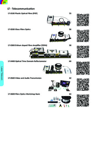
Configuring Global Attributes for Fibre Channel InterfacesConfiguring Switch Port Attribute Default ValuesCommand or ActionPurposeStep 6switch(config-if)# switchportfcrxbbcredit 5 mode FxAssigns this value if the port is operating in F mode. Therange to assign BB credits is between 1 and 64.Step 7switch(config-if# do show int fcslot/portDisplays the receive and transmit BB credit along withother pertinent interface information for this interface.The BB credit values are correct at the time theregisters are read. They are useful to verifysituations when the data traffic is slow.NoteConfiguring Global Attributes for Fibre Channel InterfacesConfiguring Switch Port Attribute Default ValuesYou can configure attribute default values for various switch port attributes. These attributes will be appliedglobally to all future switch port configurations, even if you do not individually specify them at that time.To configure switch port attributes, perform this task:ProcedureCommand or ActionPurposeStep 1switch# configuration terminalEnters configuration mode.Step 2switch(config)# no system default Configures the default setting for administrative state of aninterface as Up. (The factory default setting is Down).switchport shutdown sanTipStep 3switch(config)# system defaultswitchport shutdown sanConfigures the default setting for administrative state of aninterface as Down. This is the factory default setting.TipStep 4switch(config)# system defaultswitchport trunk mode autoThis command is applicable only to interfaces forwhich no user configuration exists for theadministrative state.This command is applicable only to interfaces forwhich no user configuration exists for theadministrative state.Configures the default setting for administrative trunk modestate of an interface as Auto.NoteThe default setting is trunk modeon.About N Port Identifier VirtualizationN port identifier virtualization (NPIV) provides a means to assign multiple FC IDs to a single N port. Thisfeature allows multiple applications on the N port to use different identifiers and allows access control, zoning,Cisco Nexus 5000 Series Switch CLI Software Configuration GuideOL-16597-0113
Verifying Fibre Channel InterfacesEnabling N Port Identifier Virtualizationand port security to be implemented at the application level. The following figure shows an example applicationusing NPIV.Figure 2: NPIV ExampleEnabling N Port Identifier VirtualizationTo enable or disable NPIV on the switch, perform this task:Before You BeginYou must globally enable NPIV for all VSANs on the switch to allow the NPIV-enabled applications to usemultiple N port identifiers.NoteAll of the N port identifiers are allocated in the same VSAN.ProcedureCommand or ActionPurposeStep 1switch# configuration terminalEnters configuration mode.Step 2switch(config)# npiv enableEnables NPIV for all VSANs on the switch.Step 3switch(config)# no npiv enableDisables (default) NPIV on the switch.Verifying Fibre Channel InterfacesVerifying SFP Transmitter TypesThe SPF transmitter type can be displayed for a physical Fibre Channel interface (but not for a virtual FibreChannel).The small form-factor pluggable (SFP) hardware transmitters are identified by their acronyms when displayedin the show interface brief command. If the related SFP has a Cisco-assigned extended ID, then the showinterface and show interface brief commands display the ID instead of the transmitter type. The showCisco Nexus 5000 Series Switch CLI Software Configuration Guide14OL-16597-01
Configuring Fibre Channel InterfacesVerifying Interface Informationinterface transceiver command and the show interface fc slot/port transceiver command display both valuesfor Cisco supported SFPs.Verifying Interface InformationThe show interface command displays interface configurations. If no arguments are provided, this commanddisplays the information for all the configured interfaces in the switch.You can also specify arguments (a range of interfaces or multiple, specified interfaces) to display interfaceinformation. You can specify a range of interfaces by entering a command with the following example format:interface fc2/1 - 4 , fc3/2 - 3The following example shows how to display all interfaces:switch# show interfacefc3/1 is up.fc3/3 is up.Ethernet1/3 is up.mgmt0 is up.vethernet1/1 is up.vfc 1 is up.The following example shows how to display multiple specified interfaces:switch# show interface fc3/1 , fc3/3fc3/1 is up.fc3/3 is up.The following example shows how to display a specific interface:switch# show interface vfc 1vfc 1 is up.The following example shows how to display interface descriptions:switch# show interface -------------------------------------fc3/1test intestEthernet1/1-vfc 1-.The following example shows how to display all interfaces in brief:switch# show interface briefThe following example shows how to display interface counters:switch# show interface countersThe following example shows how to display transceiver information for a specific interface:switch# show interface fc3/1 transceiverNoteThe show interface transceiver command is only valid if the SFP is present.The show running-configuration command displays the entire running configuration with information forall interfaces. The interfaces have multiple entries in the configuration files to ensure that the interfaceCisco Nexus 5000 Series Switch CLI Software Configuration GuideOL-16597-0115
Default Fibre Channel Interface SettingsVerifying BB Credit Informationconfiguration commands execute in the correct order when the switch reloads. If you display the runningconfiguration for a specific interface, all the configuration commands for that interface are grouped together.The following example shows the interface display when showing the running configuration for all interfaces:switch# show running configuration.interface fc3/5switchport speed 2000.interface fc3/5switchport mode E.interface fc3/5channel-group 11 forceno shutdownThe following example shows the interface display when showing the running configuration for a specificinterface:switch# show running configuration fc3/5interface fc3/5switchport speed 2000switchport mode Echannel-group 11 forceno shutdownVerifying BB Credit InformationThe following example shows how to display the BB credit information for all Fibre Channel interfaces:switch# show interface bbcredit.fc2/3 is trunkingTransmit B2B Credit is 255Receive B2B Credit is 12Receive B2B Credit performance buffers is 37512 receive B2B credit remaining255 transmit B2B credit remainingDefault Fibre Channel Interface SettingsThe following table lists the default settings for native Fibre Channel interface parameters.Table 5: Default Native Fibre Channel Interface ParametersParametersDefaultInterface modeAutoInterface speedAutoAdministrative stateShutdown (unless changed during initial setup)Trunk modeOn (unless changed during initial setup)Trunk-allowed VSANs1 to 4093Interface VSANDefault VSAN (1)Cisco Nexus 5000 Series Switch CLI Software Configuration Guide16OL-16597-01
Configuring Fibre Channel InterfacesVerifying BB Credit InformationParametersDefaultBeacon modeOff (disabled)EISL encapsulationDisabledData field size2112 bytesThe following table lists the default settings for virtual Fibre Channel interface parameters.Table 6: Default Virtual Fibre Channel Interface ParametersParametersDefaultInterface modeAutoInterface speedn/aAdministrative stateShutdown (unless changed during initial setup)Trunk moden/aTrunk-allowed VSANsn/aInterface VSANDefault VSAN (1)EISL encapsulationn/aData field sizen/aCisco Nexus 5000 Series Switch CLI Software Configuration GuideOL-16597-0117
Configuring Fibre Channel InterfacesVerifying BB Credit InformationCisco Nexus 5000 Series Switch CLI Software Configuration Guide18OL-16597-01
Configuring Fibre Channel Interfaces Thischaptercontainsthefollowingsections: ConfiguringFibreChannelInterfaces,page1 Configuring Fibre Channel Interfaces