Transcription
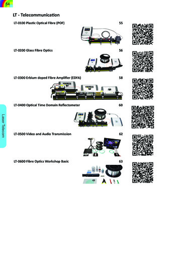
54LT - TelecommunicationLaser TelecomLT-0100 Plastic Optical Fibre (POF)55LT-0200 Glass Fibre Optics56LT-0300 Erbium doped Fibre Amplifier (EDFA)58LT-0400 Optical Time Domain Reflectometer60LT-0500 Video and Audio Transmission62LT-0600 Fibre Optics Workshop Basic63
55LT-0100 Plastic Optical Fibre (POF)3101011, 12, 13, 14167174567A plastic fibre is an equivalent tooptical multimode glass fibres.Whereas glass fibre are used forlong distance and high speeddata transmission, plastic fibresare commonly used for local area networksfor data and signal transmission. Nowadaysthe transmission losses with 12 dB / 50 m ofthese fibres are significantly higher than thoseof the glass fibres. A lot of effort is undertakento remove this disadvantage, since the manufacturing and installation costs of plastic fibresare comparably low. For signal transfer at shortdistances optical plastic fibre play an importantrole. Especially in harsh environments for ex-Si Photodetector ReceiverFibre Y Couplerample high voltage power stations, signal transfer via light and plastic fibre can be performedalmost free of noise. The light transfer in allplastic fibres is achieved by using a plastic corewhich is coated with a material to obtain a stepindex profile. Typical diameters are 1 mm forthe core which simplifies the coupling of lightcompared to glass fibres significantly. Also thepreparation process, the cutting of the fibre canbe done with a simple cutter blade instead ofusing special cleaving tools as it is the case forglass fibres.The goal of this experimental system is to teachand train the handling with and the signal transmission via optical plastic fibre. As transmitterLED is independently controlled.GPDRed LEDGreen LEDL1Y couplerPlastic fibre optic1,10, 20 or 30 mRPDFibre adjusterDichroic beam splitter plateThe light of the fibre coupled red and the greenfibre coupled LED is merged by an also fibrecoupled Y coupler and is available at the fibreoutput jack. The power and modulation of eachLT-0100 POF - Plastic Fibre Optics consisting of:Item123456789101112131415161718CodeQty. DescriptionCA-04502 BNC connection cable 1 mCA-06101 Plastic fibre connector mounting setDC-00301 Dual channel LED transmitter and receiverLQ-02121 Red LED in C25 with fibre jackLQ-02221 Green LED in C25 with fibre jackMM-00201 Mounting plate C25 on carrier MG20MM-04801 Four axes kinematic plastic fibre mountMM-05601 Two mounting plates C25 on MG20MP-01501 Optical Bench MG-65, 500 mmOC-25002 Plastic optical fibre ST/FSMA, length 0.25 mOC-25021 Plastic optical fibre ST/ST, length 1 mOC-25101 Plastic optical fibre ST, length 10 mOC-25201 Plastic optical fibre ST, length 20 mOC-25301 Plastic optical fibre ST, length 30 mOC-25902 ST-POF couplerOM-00701 Dichroitic beam splitter unit on MG65OM-09201 POF Y coupler in C25UM-LT011 Manual Plastic Fibre Opticsa green and red LED is used to demonstrateindependent dual wavelength data transmissionin a single fibre. The radiation of the LED iscoupled by means of a Y coupler into the fibre.The light at the exit of the fibre passes a dichroic beam splitter plate which is coated in sucha way that the green radiation will be totallyreflected whereas the red radiation is transmitted. Two photo detectors convert the light signal into electrical signals which are amplifiedby the receiver module and can be displayedon a two channel oscilloscope for further investigation. The transmitter unit contains twoindependent drivers for both the LED as well asinternal modulators.Details page128 (28)128 (31)120 (3)118 (8)119 (11)93 (1)97 (31)97 (37)92 (8)109 (98)109 (99)109 (100)109 (101)109 (102)109 (103)111 (9)116 (45)Appearing emission spectrumBy changing the individual power of the LEDthe merged light appears in a spectral rangefrom green via yellow to red. After passing theplastic fibre optics the light is guided by meansof the fibre adjuster to the lens L1, which focuses the light onto the photodetector GPD (green)and RPD (red). The dichroic beam splitter plateseparates the green and red part of the incidentlight.To measure the spectral absorption of the fibredifferent length of fibres are used. By combining the 10 m, 20 m and 30 m a variety of10,20,30,40,50 and 60 m can be achieved.Green LEDRed LEDPOFrel. attenuationWavelength 400500600700 nmFig. 3.1: Spectral emission of the LED andthe relative POF attenuationLaser TelecommLED TransmitterLED ModulationLosses in Plastic FibreHow it worksPlastic Fibre HandlingDichroic Beam SplitterData TransmissionIntroduction Keywords9
56How it worksLaser TelecomIntroduction KeywordsLT-0200 Glass Fibre OpticsFibre strippingCoupling Light to FibreCut of wavelengthFibre cleaving and cuttingSignal transferSpeed of LightThe basic idea to use guided lightfor data communication was published in 1939 by H. Buchholz inhis paper „Die Quasioptik derUltrakurzwellenleiter“ (The quasioptical behaviour of ultra short wave guides).However it took more than 20 years to developfirst realistic technical solutions mainly encouraged by the first available diode lasers in 1962.These new light sources are ideally suited astransmitter because of their ability to be modulated and in addition, as we know today, theycan be produced in large numbers at low prices.Nowadays the world wide communication isbased on fibre optics combined with laser diodes and the development in this area belongs tothe most exciting ones in this century. In 1977based on the experience and results rapid investigation in other fields than communicationswere initiated, leading for example in the development of fibre gyros for navigation purposesDiode Laser CharacterisationNumerical Aperture of Fibreof air planes. In principle this new technologydoes not require a new understanding of thephysics because the related phenomena are wellknown and can be considered as a combinationof classical optics and lasers. However for therealisation a lot of technical problems had tobeen solved. In the fibres mainly used in communication the light is guided within a „glasstunnel“ with a diameter of 9 µm only. The necessary mechanical components as well the production process of the fibres itself were subjectof comprehensive developments. Considerableefforts today are undertaken to reduce fibretransmission losses by using so called active fibres and in the realisation of integrated opticaldevices for distributing and receiving signals.The field of fibre optics is still expanding andof high common interest. Therefore this experiment is considered as a introduction to this important technology.The trainees are introduced firstly to preparea bare optical fibre in such a way that suitableend faces are obtained. This process of fibrestripping and cleaving is a recurrent practiceeither in research labs or telecommunication.By means of collimation optics the beam ofthe diode laser is made almost parallel before itenters the microscope objective which focusesthe light into the multimode fibre. By observingthe output at the exit of the fibre the couplingefficiency is optimised by adjusting the precisemounts. Once a strong signal has been obtainedthe numerical aperture of the fibre is measuredby means of the photodetector mounted to thepivot arm. In a next step the photodetector isconnected to an oscilloscope and the injectioncurrent of the diode laser is modulated. Boththe diode laser signal and fibre output are displayed on the scope and the time of flight becomes apparent and can be measured. Fromthis measurement either the speed of light orthe length of the fibre is determined.Characterising the laser diodeGoniometerPhotodiodeLaser diodeThe light of the diode laser is characterised bymeasuring the output power versus the injection current and the spatial intensity distribution by using the provided photodetector whichis mounted onto a pivot arm.Measurements with the optical fibreCollimatorLaser diodeGlass fibreFocussingGoniometerPhotodiodeTranslation stageBy means of collimation optics the beam of thediode laser is made almost parallel before itenters the microscope objective which focusesthe light into the multimode fibre. By observingthe output at the exit of the fibre the couplingefficiency is optimised by adjusting the precisemounts. Once a strong signal has been obtainedthe numerical aperture of the fibre is measuredby means of the photodetector mounted to thepivot arm. In a next step the photodetector isconnected to an oscilloscope and the injectioncurrent of the diode laser is modulated. Boththe diode laser signal and fibre output are displayed on the oscilloscope and the time of flightbecomes apparent and can be measured. Fromthis measurement either the speed of light orthe length of the fibre is determined.
57Description of the components1257111115613148910The light of the laser diode (15) is collimated(13) and launched by means of a precise adjustable objective (14) into the fibre which is placedon top of a fibre chuck which is fixed to thetranslation stage (8). This allows the precisepositioning to the focus of the laser light. The fibre is connected via so called fibre pigtails withthe drum of 1000 or 2000 m multimode fibre(12). The end of the fibre is placed on top of thefixed fibre chuck of the goniometer (9). A photodetector (6) is attached to the goniometer armand measures the emerging output power of thefibre. The photo current is converted with thejunction box (7) into a voltage and is measuredeither by a digital voltmeter or oscilloscope. Thecontroller (5) stabilises and displays the temperature and injection current of the laser diodeplus the modulation of the injection current.Fig. 3.5: Coupling light to fibreFig. 3.8: Fibre preparation toolsA fibre is called pigtailed, when one end is bareand the other has a fibre connector (Fig. 3.7).The use of such fibre interfaces has the advantage that the training of the fibre preparationwill not affect the main fibre (12). It has furthermore the advantage that without the need for realignment other fibre drums can be connectedor connected into series to extend the overalllength. It allows also to measure the fibre attenuation, however including the connector losses.To prepare the fibre for operation a flat andclean surface of the fibre face is needed. Firstlythe plastic cover and cladding is removed bythe so called Miller’s pliers (4) and secondlyscratched and broken by the fibre breaking tool(3). This practical work gives the students important skills to work in the exciting world offibre telecommunication.1.01.0Fig. 3.7: Set of fibre pigtails (11)34Fig. 3.6: Measuring spatial distributionMeasurement examples1 Diode laser power [W]T 20 C T 30 C 0.8 T 40 C0.60.4Θ 0.20[deg] 02004006008001000 mAFig. 3.2: Output power versus injectioncurrent0.0-4017181902040Fig. 3.3: Laser diode angular power distributionLT-0200 Glass Fibre Optics consisting of:Item12345678910111213141516-20CodeQty. DescriptionCA-00601 Infrared display card 0.8 -1.4 µmCA-04502 BNC connection cable 1 mCA-06201 Optical fibre scriber and breakerCA-06301 Adjustable plastic cover stripperDC-00401 Diode laser controller MK1DC-01201 Si-PIN Photodetector, BPX61 with connection leadsDC-03801 Photodetector Junction Box ZB1MM-04901 Translation stage with bare fibre holderMM-04941 Rotation stage with bare fibre mountMP-01501 Optical Bench MG-65, 500 mmOC-20401 Set of 10 ST pigtailed MM fibreOC-24501 Multimode fibre 1000 m, 50/125 µm, ST panel jacksOM-06201 Collimating optics on carrier MG20OM-09501 MO coupling optics, 4 axes kinematic mountOM-L5001 Diode laser module 808 nm on C20UM-LT021 Manual Glass Fibre OpticsOption (order separately)OC-24401 Singlemode fibre, 1000 m, 9/125 µm, ST panel jacksOC-24601 Multimode fibre, 2000 m 50/125 µm, ST panel jacksRequired Option (order separately)CA-02001 Oscilloscope 100 MHz digital, two channelDetails page126 (10)128 (28)128 (32)128 (34)120 (4)121 (14)123 (30)97 (32)97 (33)92 (8)107 (84)109 (96)114 (30)117 (46)118 (55)109 (95)109 (97)127 (19)0.0-40[deg] -2002040Fig. 3.4: Intensity distribution at fibre exitto determine the numerical apertureLaser OFF tFig. 3.9: Measurement of the time of flightThe facility to modulate the injection currentof the diode laser makes it possible to measurethe time of flight Δt of a laser pulse via 1000m,2000 m or 3000 m of fibre. With the knownlength of the fibre even the speed of light canbe determined and the index of refraction of thefibre calculated.Laser TelecommDetails
58IntroductionKeywordsLT-0300 Erbium doped Fibre Amplifier (EDFA)Laser TelecomHow it worksOptical AmplifierCoupling light to fibreLifetime of Excited StateThe success of the optical communication would not have beenperfect without the invention ofoptical amplifier. A lot of efforthas been invested in reducing thelosses in optical fibres. However the residuallosses limiting a maximum distance of around80 km for a single mode fibre before the signalbecomes to weak for detection. In principle theweak light could be amplified by an electronicamplifier and fed again into the fibre. However,this foils the extraordinary high bandwidth ofoptical fibre and a pure optically working amplifier is required. The concept of optical amplification is part of each laser and optical amplification is a well established technology. Thegenius underlying concept is the combinationwith an optical fibre and amplifier in one piecewhich has been realized in the erbium doped fibre amplifier (EDFA). The EDFA consists of anoptical fibre which is doped with a defined concentration of Erbium atoms. By means of a couLaser diode 980 nmFibre couplerOptical PumpingSignal AmplificationFibre Laser SpikingErbium doped optical AmplifierFibre Laserpler the light of a pump source is fed into the fibre exciting the erbium atoms which are actingnow as amplifier. The pump wavelength is typically 980 nm and the amplification takes placearound 1500 nm, the same range as the opticalcommunication signal. Due to the coherence ofthe amplification process the amplified streamof photons are indistinguishable with respect tothe incoming ones. What a great idea!This experiment is designed to avoid timeconsuming adjustments procedures to launchthe light of two diode laser into the amplifying EDFA fibre. As fibre coupled system eachcomponent can viewed to enhance the understanding of the EDFA concept. It starts with thepump laser diode emitting a wavelength of 980nm. The pump radiation is coupled via a single mode fibre beam Y coupler into the Erbiumdoped fibre (EDF). The EDF has a length ofabout 16 metre and is coiled up on a drum. Assignal source a laser diode emitting at 1550nm is used. Its radiation passes the same fibreErbium doped fibrePhotodiodeLaser diode 1550 nmThe experiment uses two laser diodes, oneemits a wavelength of 980 nm with a power of300 mW and serves as pump source. The other emits a wavelength of 1550 nm with lowerpower around 5 mW and serves as signal source.Both diode laser are fibre coupled and are con-coupler is also launched into the EDF. At theoutput end of the EDFA an InGaAs detector isused for the detection of the 980 nm radiationas well as for the detection of the 1550 nm radiation respectively. A variety of measurementsare carried out like the characterization of thetwo diode lasers. The injection current of eachlaser can be set independently by two controllers. In a next experiment the 980 nm radiationis coupled into the EDF and the created fluorescence is detected and monitored on an oscilloscope. The controller allows the modulatedoperation of the diode laser in such a way thatthe fluorescence decay the excited erbium atoms are displayed and the life time determined.By a further increase of the power of the pumpdiode laser the EDFA turns into a fibre laserwhich dynamic behaviour like distinctive spiking. Finally the 1550 nm radiation is fed into theEDFA and the gain is measured as function ofthe pump power.placed in front of the photodetector. Each diodelaser has its own controller to set the individualinjection current for the measurement of theEDFA as function of the pump and the signalpower.Fibre patch cable PhotodiodeInterference filter 1550 nmnected via single mode patch cables to the fibrecoupler. The pump as well as the signal waveenter the Erbium doped fibre and the signalsleaving the fibre are detected by a InGaAs photodetector. In order to detect only the 1550 nmradiation a laser line or interference filter isLaser diode 1550 nmIn such case, the laser diode is directly coupledto the photodiode by means of fibre patch cableand the photocurrent is converted by means ofthe provided junction box into a linear voltage.Erbium doped fibreLaser diode 980 nm4PhotodiodeI11/2rapid transfer4Interference filter 1550 nmThis setup uses only the pump diode laser tocharacterize the Erbium doped fibre in termsof measuring the lifetime of the excited stateand even to perform some fibre laser experiments. For this purpose the 980 nm laser diodeis directly coupled to the Erbium doped fibre.A photodiode monitors the output of the EDFAfibre. It will be a mixture of not absorbed pumppower of 980 nm and the created fluorescenceof 1550 nm. Of special interest is the 1550 nmradiation and therefore a line filter is placed infront of the photodiode.I13/2980 nm1550 nm4I15/2Fig. 3.10: EDFA amplification process
59Description of the components31631213754917149The amplifying medium is a 16 m long Erbiumdoped fibre which is coiled up on a drum (13)and terminated with single mode ST fibre paneljacks. The pump laser source (17) consists of968a 980 nm laser diode in a so called butterflyhousing which also contains a Peltier elementto control the temperature of the laser chip. Theradiation is available at a single mode ST fibrepanel jack. By means of single mode fibre patchcables (12 and 9) both laser sources are connected to the wavelength division multiplexer(14, WDM). The combined radiation enters viaa single mode patch cable the Erbium doped fibre (13). The output of the fibre is connected viaa patch cable to the photodetector (4) which isconnected to the junction box (5) where the detected photocurrent is converted into a voltageand can be displayed on an oscilloscope. Eachlaser diode has its own controller (3) whichmaintains the set values for the injection current and temperature.Measurements Diode laser power69T 10 C 10T 30 C T 40 CInjection current In first experiments the characteristics of thediode laser modules are measured. These aremainly the output power versus the injectioncurrent with the temperatures as parameter.Pump laser power versus injection currentand temperatureLaser operation and Gain Measurements30 Gain [dB]Signal strength lowmedium20high10Fig. 3.12: Lifetime of the excited stateFor the measurement for the lifetime of the excited state (Fig. 3.12) and the fibre laser operation (Fig. 3.13) only the pump laser (17) is connected to the Erbium doped fibre. The full setupis chosen to measure the gain of the EDFA.rel. Pump power (injection current mA)Fig. 3.13: Spiking of the Erbium laserThe gain is measured as a function of the pumppower with the for signal strength of the 1550nm radiation as parameter. If the pump powerexceeds a certain value, the EDFA start to workas laser and falsifies the gain measurement.LT-0300 Erbium doped Fibre Amplifier EDFA consisting of:ItemCodeQty. Description1CA-00601 Infrared display card 0.8 -1.4 µm2CA-04503 BNC connection cable 1 m3DC-00402 Diode laser controller MK14DC-01641 InGaAs Photodetector ST with connection leads5DC-03801 Photodetector Junction Box ZB16MM-00203 Mounting plate C25 on carrier MG207MP-01301 Optical Bench MG-65, 300 mm8MP-01501 Optical Bench MG-65, 500 mm9OC-04301 Fibre jacket in C25 mount10OC-07601 Laser line filter 1550 nm in C25 mount11OC-20103 ST/ST SM Fibre patch cable, length 0.25 m12OC-20201 ST/ST SM Fibre patch cable, length 1 m13OC-22301 Erbium doped fibre unit, ST terminated, length 16 m14OC-23001 SM-WDM coupler 980/1550 nm unit ST terminated15 OM-05401 Diode laser module 980 nm, ST fibre connector16 OM-05501 Diode laser module 1550 nm, ST fibre connector17 UM-LT031 Manual EDFARequired Option (order separately)18CA-02001 Oscilloscope 100 MHz digital, two channel02030405060HighlightsDetails page126 (10)128 (28)Advanced and top level experiments120 (4)122 (18)Outstanding features for an all fibre coupled123 (30)Erbium doped fibre amplifier93 (1)92 (7)Intended institutions and users:92 (8)101 (21)Physics Laboratory103 (42)Telecommunication107 (81)Engineering department107 (82)Electronic department108 (91)Biophotonics department108 (91)Chemistry department113 (23)113 (24)127 (19)70Fig. 3.14: Gain versus pump power and signal strength, small signal and large signalamplification, gain saturationLaser TelecommFig. 3.11: Setup to characterize the individual diode laser modules
60How it worksLaser TelecomIntroductionKeywordsLT-0400 Optical Time Domain ReflectometerPulsed Laser DiodeFibre cuttingLosses of FibresLight EchoesOptical FibreSpeed of LightLosses of ConnectorsThe whole worldwide communication is based on fibre opticalnetworks encompassing the entireworld and is extremely importantin view of economical and security aspects. Meanwhile fibre optical networkslines already terminating at homes thus forming a complex structure. The proper workingand condition is of vital mutual interest of theprovider and customer. Fibre lines can be damaged during road works, earth movements andeven by late effects of production imperfections. Whatever the reason of the malfunctionof communication networks are, the problemsneeds to be solved as soon as possible. This isthe moment of the mission of the “Optical TimeReflectometry” (OTDR). An OTDR is an optoelectronics instrument that uses time-domainreflectometry to characterize and locate faultsFibre StrippingLength of FibreFast Photo Detectorin optical fibres. The underlying idea is to senda short pulse into the fibre and “listening” toany echoes coming back from it. At each fibreimperfection, especially at the face of a brokenfibre a lot of light is reflected or scattered backinto the fibre. From the time of flight of the input pulse and the occurrence of the echoes thedistance to the faulty position is found and theservice repair team can then do their job.However, the OTDR covers more possibilities,it is the only device which can measure theattenuation or losses of an optical fibre nondestructively. Such losses in optical fibres canbe caused by several reasons, mainly due to optical and mechanical imperfections during themanufacturing process, or by extra mechanicalstress on the fibres like unspecified bending ortension.These days OTDR devices form a small andPDL2PLDAdjustable launching opticsOptical glass fibreRPDcompact and an indispensable tool in opticalfibre communication. The aim of this experiment is to set up an OTDR in such a way thatthe trainees can identify, align and control therequired components like the pulsed diode laser, coupling light into the fibre via a polarisingbeam splitter. The path of the returning lightis bent due to its changed polarisation at thebeam splitter cube towards the fast photodetector. The returned light intensity carries theinformation about the losses by an exponentialdecay in time, upward peaks for reflections anddownward peaks for losses at joints caused either by splices or connectors. The experimentcomes with two drums carrying each 1000 mof optical fibre. The fibres are interconnectedvia two ST patch cable whereby one end of eachfibre is left as it is to teach fibre stripping andcutting.further enhances the right polarisation in orderto get most of the back scattered light whichanyhow has a very small power. This requireshighly sensitive photodiodes and fast amplifier.cracksL1reflection 4%Quarter waveplatePolarising beam splitter plateMain reasons for losses in optical fibre are mechanical cracks, unavoidable scatter centresdue to the production process and reflections(see Fig. 3.15). These three imperfections creating backward oriented scatter light, where byoptical connectors acting as a photon sink.The idea of an OTDR is to detect this back scattered light and analyse its amplitude and temporal behaviour. For this purpose the pulse of thelaser diode (PLD) is launched via a polarisingbeam splitter plate into the optical fibre. Thepolarisation of the back scattered is changedso that it will be reflected at the beam splittertowards the detector. The quarter waveplate100% 96%scatter centresFig. 3.15: Losses in optical fibreWithin this experiment an extra photodetectoras alignment aid is used. It serves as indicatorfor the coupling efficiency of the laser light intothe fibre. Further more in first experiments thetime of flight inside the fibre can be measuredwith this photodetector as well.
611352071861011162119151798122214The light of the pulsed diode laser (9) is collimated (11) to an almost parallel beam andguided via the polarising beam splitter (21), thequarter wave plate (17) and the launching opticsinto the fibre (20) under test. The fibre drum isconnected via a pigtailed fibre patch cable tothe adjustable fibre holder (12). The exit of thefibre drum is connected via a patch cable (18)to the photodetector (6). The junction box (8)converts the photocurrent into a voltage whichis displayed on an oscilloscope. The adjustable launching optics and the translation stageof (12) is used to couple the light into the fibrewhile observing the signal of the photodetector(6) on the oscilloscope. Once the optimum settings has ben achieved, the signal of the photodiode (7) is monitored, which represents theintensity of the back scattered light as shownin (Fig. 3.16).Details34Fig. 3.18: Coupling light to fibreFig. 3.20: Fibre preparation toolsFig. 3.19: Set of fibre pigtails (11)A fibre is called pigtailed, when one end is bareand the other has a fibre connector Fig. 3.18.The use of such fibre interfaces has the advantage that the training of the fibre preparationwill not affect the main fibre (19). It has furthermore the advantage that without the need for realignment other fibre drums can be connectedor connected into series to extend the overalllength. It allows also to measure the fibre atten-Kea measurements log(Intensity)0“End of fibre” peak“end of fibre” peak-2-4Puls laserFig. 3.16: OTDR back scatter signallinear regression-6024time [µs] 6810LT-0400 OTDR - Optical Time Domain Reflectometer consisting of:Item123456789101112131415161718192021222312Fig. 3.17: Logarithmic representation of theback scatter signalCodeQty. DescriptionCA-00601 Infrared display card 0.8 -1.4 µmCA-04502 BNC connection cable 1 mCA-06201 Optical fibre scriber and breakerCA-06301 Adjustable plastic cover stripperDC-00501 Pulsed laser diode controller MK1DC-01241 Si-PIN Photodetector with ST jack and connection leadsDC-02201 SiPIN Photodetector, ultrafast with amplifierDC-03841 Photodetector junction box w. amplifierLQ-03501 Pulsed diode laser in housingMM-00202 Mounting plate C25 on carrier MG20MM-00901 XY adjuster on MG20MM-04901 Translation stage with bare fibre holderMP-01301 Optical Bench MG-65, 300 mmMP-01501 Optical Bench MG-65, 500 mmOC-00601 Biconvex lens f 60 mm in C25 mountOC-01701 Collimator 808 nm in C25 mountOC-08401 Quarter-wave plate in C25 mountOC-20301 ST/ST MM Fibre patch cable, length 1 mOC-20401 Set of 10 ST pigtailed MM fibreOC-24502 Multimode fibre 1000 m, 50/125 µm, ST panel jacksOM-00201 Adjustable beam splitter on tee-piece MG65OM-09501 MO coupling optics, 4 axes kinematic mountUM-LT041 Manual OTDRRequired Option (order separately)24CA-02001 Oscilloscope 100 MHz digital, two channelDetails page126 (10)128 (28)128 (32)128 (34)120 (5)121 (15)122 (22)123 (31)119 (15)93 (1)94 (8)97 (32)92 (7)92 (8)99 (5)100 (13)101 (24)107 (83)107 (84)109 (96)110 (3)117 (46)127 (19)The Fig. 3.17 shows the evaluation of the datafrom the scope (Fig. 3.16). To obtain the lossesof the fibre it is necessary to scale the Y-axis inlogarithmic units. This provides a linear rangeof the applied linear regression from which theslope of it represents the losses of the fibre. Sincethe intensity at the end of the response is verylow, the noise floor dominates the signal and dueto the logarithm of small values the noise is evenenhanced in this representation. The “end of fibre” peak finally gives the length of the fibre andfrom this we gain the desired losses as dB/ km.HighlightsAdvanced and top level experimentsOutstanding features for an open frameOptical domain Reflectometer. A rich variety of professional adjustment tasksIntended institutions and users:Physics LaboratoryTelecommunication EngineeringEngineering departmentElectronic departmentLaser Telecommuation, however including the connector losses.To prepare the fibre for operation a flat andclean surface of the fibre face is needed. Firstlythe plastic cover and cladding is removed bythe so called Miller’s pliers (4) and secondlyscratched and broken by the fibre breaking tool(3). This practical work gives the students important skills to work in the exciting world offibre telecommunication.
62How it worksLaser TelecomIntroductionKeywordsLT-0500 Video and Audio TransmissionOptical Glass FibreFibre TransmitterCCD CameraAudio SourceOptical Signal DetectionPhotodetectorThis experiment comprises twodrums of multimode fibre withone 1000 m and two 2000 m longmultimode fibre. With this set datatransmission segments can berealized with a length of 1000 m, 2000 m and3000. The fibre drums are equipped with STfibre jacks and by means of the provided fibrepatch cable they can be interconnected. As sig-nal sources a colour CCD Video camera and aCD - Player as audio source are used. They areconnected to the fibre transmitter which converts the electronic signals into digital opticalsignals which are guided via the optical fibreto the optical receiver where the signals converted back to electronic audio as well as videosignal. These signals are connected to a regula
LT-0100 Plastic Optical Fibre (POF) 55 LT-0200 Glass Fibre Optics 56 LT-0300 Erbium doped Fibre Amplifier (EDFA) 58 . Optical Time Domain Reflectometer 60 LT-0500 Video and Audio Transmission 62 LT-0600 Fibre Optics Workshop Basic 63. Laser Telecomm LT-0100 Plastic Optical Fibre (POF) A plastic fibre is an equivalent to optical multimode .