Transcription
IV.Return toTable of ContentsDESIGN OF SANITARY SEWERSA.Hydraulic Design:The following procedures and criteria are to be used for sizing and hydraulic design ofgravity sanitary sewers. Generally, sewer outfalls and trunk mains shall be sized for thefuture full development of the basin using the following criteria unless more specific datais available. These design and peak flow calculations are not to be used to calculateflows for wastewater permits. Wastewater permits will be issued on the basis of currentactual land use and NCDEM guidelines (i.e. 250 gpd/house, CMUD has been grantedapproval to use 190 gpd/house, etc.).1.July 27, 1995Determine Drainage Basin and Population To Be Serveda.Outline the major basin on 1" 200' topographic maps. Identify andoutline all sub basins and identify any other basins or sub basins that willbe pumping into the sewer being designed.b.Using a planimeter or some other acceptable method, determine the areato be served. Include the basins or sub basins that will be pumped intothe sewer. If the area is undeveloped, reduce the area by 20% toaccount for streets. If the area is developed reduce the area asnecessary to allow for existing streets.c.For each basin and sub-basin, determine the existing population, landuse and zoning. Refer to the appropriate area Land Use Plan todetermine trends in land use and zoning and for predictions of populationgrowth rate.d.Estimate the "build out" population in the areas to be served when theareas are fully developed according to land use and zoning projections.Table 1 may be used, along with any population projections contained inthe Land Use Plan, in estimating this population.e.Estimate the percentage of the "build out" population that will exist in theareas in the 50th year. This percentage should be based on growth rateprojections contained in the Land Use Plan. The sewer line should besized to serve this population.IV - 1Design of Sanitary Sewers
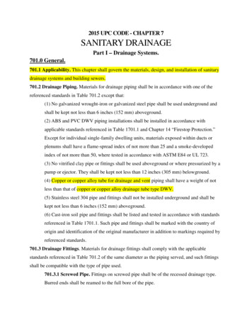
TABLE 1GUIDELINES FOR DETERMINING DOMESTIC WASTE QUANTITIESResidential AreasSingle Family, Large lotsSingle Family, Small lotsMulti Family, Small lots5-15 people/acre15-35 people/acre35-100 people/acreCommercial Areas15-30 people/acreIndustrial Areas5-15 people/acre2.3.July 27, 1995Determine The Flow:a.Determine average daily flow (design flow) for residential areas byallowing 100 gallons/day/person.b.Determine average daily flow (design flow) for industrial or commercialareas by applying the 100 gallons/day/person criterion. Add additionalflow based on research of specific zoning and any known large waterusers.c.Determine peak daily flow by multiplying the average daily flow by theappropriate peaking factor. The minimum peaking factor permitted by theNorth Carolina Department of Environmental Management is 2.5 and thisfactor should be used in the absence of specific design or flow datasupporting a higher peaking factor.Determine the minimum slope:a.From topographic maps and any vertical survey control in the area,determine the average slope of the natural drainage in the area to beserved. Determine whether any sections are significantly flatter than theaverage.b.Determine whether there are obstructions (e.g. petroleum transmissionmains) or natural terrain features that will limit the pipe slope.c.Based on (a) and (b), establish the minimum slope for the pipeline. Thisshould be used as the design slope.IV - 2Design of Sanitary Sewers
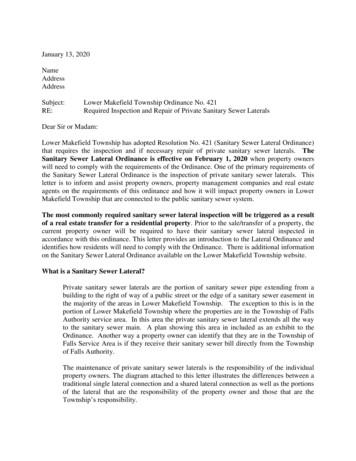
4.Size the Sanitary Sewer Pipe:a.Use the peak daily flow for calculations with pipe flowing full. This isequilavent to using average daily flow (design flow) with the pipe flowingapproximately 40% full.b.Use Manning Equation or Charts to determine pipe size.2/3Q 1.486 A Rn1/2SWhere n .013R hydraulic radius cross sectional areawetted perimeterS slopeA Cross sectional area of pipeJuly 27, 1995c.Check the velocity flowing fullV Q/AVelocity must be 2 fps and 10 fpsd.Check the pipe size and slope against Table 2 and adjust pipe size asrequired to meet the minimum design slope.IV - 3Design of Sanitary Sewers
TABLE 2MINIMUM SLOPES FOR SANITARY SEWERSAS REQUIRED BY THE N.C. STATE BOARD OF HEALTHSewer Pipe Size In InchesMinimum Slope In Feet Per 100 Feet80.40 (CMUD min. is 0.60)100.28120.22150.15160.14180.12210.10240.0830 and largerB.July 27, 1995Based on velocitycalculationsRoute Selection1.Overlay property lines onto topographic map.2.Make a preliminary layout, minimizing the number of parcels involved andparalleling property lines where possible. Avoid obvious construction problemswhere possible.3.If the average daily flow is greater than 1 MGD and the project is greater than 3miles in length, an environmental assessment is required. If there is anyevidence of wet areas, or if any project area is shown on Mecklenburg Countywetland inventory maps, a wetlands delineation is required. These should bescheduled early in the project in order that they can be considered in routeselection.4.Where an Environmental Assessment is required, obtain input from the person orfirm conducting the Environmental Assessment. Minimize environmentaldamage (wetlands, unnecessary stream crossings, damage to tree canopy overstreams, etc.)5.If the proposed route crosses or parallels a roadway, get all other utilities,including other CMUD facilities, located. Consider the NCDOT requirements forencroachments in selecting the route.IV - 4Design of Sanitary Sewers
C.6.Walk the project with survey party. Modify preliminary routing as necessarybased on field observation of terrain features, environmental considerations, andproperty damage. Maintain sufficient distance from creek to protect pipe fromwashout.7.Provide preliminary layout to survey party and if applicable, to firm or personconducting the Environmental Assessment.Survey RequirementsAll sanitary sewer lines shall be field surveyed under the supervision of a surveyorregistered in North Carolina.1.Vertical control shall be tied to NGS, NCGS or established CMUD vertical controlpoints. Temporary bench marks shall be established at each proposed manholeand tied back to the established vertical control with a maximum error of0.03’ M , where M is the number of miles of level loop. The elevation base,NAVD 27 or NAVD 88, shall be indicated on the cover sheet of each set of plans.2.Horizontal control shall be tied to North Carolina Grid Coordinates.3.Centerline shall be cut and staked. Iron hubs shall be installed at all angle pointsand at all manhole locations.4.Profile data shall include centerline shots at manholes and at 50 foot intervalsalong centerline and at all grade break points. When paralleling adjacentstreams, stream bed elevations are required at each manhole.5.Where cut or fill slopes are necessary for construction, cross sections shall beprovided at fifty foot intervals along the centerline.6.The bearing of each sewer reach (manhole to manhole) shall be shown asdegrees-minutes-seconds (to least count of instrument used), and the distancebetween manholes shall be shown to the nearest 0.01 foot.Sewer lines in new subdivision streets are excluded from these requirements when thesewer plan and profile is tied to proposed street layouts in a manner acceptable toCMUD. However, before construction begins, the street rough grading must becompleted, the sewer lines must be construction staked and cut sheets must beprovided to CMUD. Cut sheets shall be signed by an NC registered surveyor or by thecontractor's designated responsible employee.D.Rights-Of-Way And Construction Easements1.July 27, 1995Permanent right-of-way and temporary construction easements shall be providedaccording to Table 3. Temporary construction easements should be increasedfor difficult construction areas (e.g. sewers on steep slopes).IV - 5Design of Sanitary Sewers
Construction within wetlands shall be limited to a disturbed width of 40', inaccordance with Nationwide Permit No. 12 issued by the Corps of Engineers.July 27, 19952.When a sewer must closely parallel a creek, two thirds to three fourths of theconstruction easement shall be on the side away from the creek.3.A separate right-of-way map shall be prepared for each individual propertycrossed. All maps shall be on standard CMUD sheets, shall conform to therequirements of the standards of practice for land surveying in North Carolina,Section 1600 of The Board Rules and shall contain the following:a.The entire property boundary shall be shown on the map with theproposed right-of-way clearly shown. For large properties, right-of-waydetails must be shown by separate insets at reduced scale. Not to scaleinsets may be used when necessary to clearly convey details.b.Every point where the sewer center line or right-of-way crosses aproperty line must be tied to an identifiable property corner.c.The property owners name, deed book and page where the deed isrecorded, and the current property tax code must be shown on each map,including adjoining parcels.d.All manhole locations must be shown, whether at angle points or on line.Show Bearings between angle points and centerline distances alonglines.e.Widths for permanent rights-of-way and temporary constructioneasements must be shown and labeled.f.The parcels on a project shall be numbered sequentially, beginning with#1 at the downstream end. The parcel number shall appear in a triangleabove the owner's name and in the title block.g.All maps must be on 8 " x 14" vellum or mylar with a standard CMUDtitle block. The title block shall include the following:a.Title as: Sanitary Sewer to Serve:Project Name, or Water Meter Easement to Serve Project Name.b.Property of current property owner, Job number, file number andscale.h.Include a vicinity map and a north arrow with basis.i.Proposed right-of-way must be shaded.IV - 6Design of Sanitary Sewers
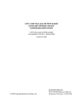
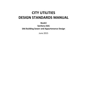
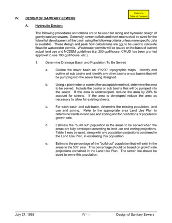
j.July 27, 1995Submit an original map and one copy with the original signature andoriginal seal of the N.C. Registered Surveyor, as required by G.S. 4730(M). In addition, seven (7) blueline copies are required.4.Check right-of-way maps against construction plans and make sure they agree.When a revision is made, make sure that both the plans and the affected right-ofway maps are changed and that the changes are recorded in the revision blockson both documents.5.When paralleling property lines, make the permanent right-of-way boundarycontiguous with the property line. Try to keep the construction easement on thesame property. Don't create a new parcel just for a construction easementunless the topography requires it (e.g. where the easement would otherwise bein a creek).6.The sanitary sewer right-of-way may overlap storm drainage right-of-wayaccording to the following Standard Detail:IV - 7Design of Sanitary Sewers
July 27, 1995IV - 8Design of Sanitary Sewers
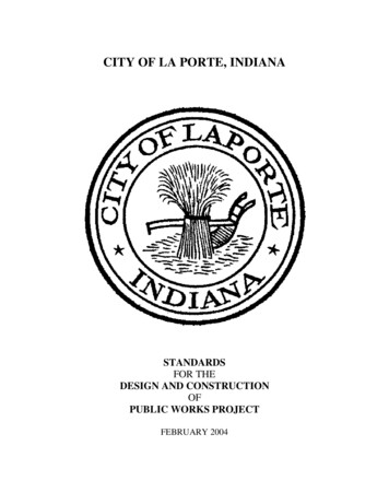
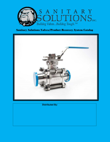
TABLE 3RIGHT-OF-WAY AND CONSTRUCTION EASEMENTS REQUIRED FOR CMUD CONSTRUCTION PROJECTS(All Numbers Are In 2550302050253555253055302555253055253560303060July 27, 1995IV - 9Design of Sanitary Sewers
E.Sewer Location, Manhole Spacing, And Venting1.Gravity sewer lines serving drainage basins shall follow the natural drainagepattern of the basin as closely as possible. Specific horizontal alignment shouldbe made with due consideration to property lines, topography, environmentaldamage, and property owner wishes. Where possible, elevations should be setso that the top of the pipeline is at least four feet below the natural grade and atleast one foot below stream or drainage channel beds.2.Sewer lines shall be laid on straight lines between manholes and at constantgrade. Outside street rights-of-way and landscaped areas, manhole rims shallbe at least two feet above finished grade. Within street rights-of-way and inlandscaped (lawn) areas, manhole rims shall be flush with finished grade.Manholes shall be vented, by use of vented covers or external vent structures,only as required for proper pipe ventilation and to insure proper hydraulicperformance (e.g. inverted siphon manhole). As a general guideline, vents arerequired at intervals of approximately 1,000 feet. All non-vented manholes shallhave solid covers, and all frames and covers subject to flooding or inflow fromstorm water shall be sealed according to current standard specifications.Manholes with external vents shall have sealed frames and covers with the ventinlet two feet above the 100 year flood protection elevation.The number of manholes shall be held to a minimum subject to the following:a.Manholes shall be placed at all horizontal and vertical break points and atthe confluence of two or more separate lines.b.Maximum manhole spacing shall be as follows:MAX. MANHOLE SPACINGPIPE SIZE8" - 12"15" - 27"30" - 42"Over 42"c.July 27, 1995500'550'700'800'For sewers 15-inches in diameter and smaller, allow a 0.2' vertical dropthrough each manhole. Where the grade is critical, or where the gradeexceeds 5%, this drop can be reduced. No drop is required throughmanholes for sewers 18" in diameter and larger. Drops throughmanholes should be limited to prevent turbulent conditions. Outsidedrops should be used when the drop through the manhole is 1.5 feet orgreater, according to the Standard Details. Inside drops may be allowedin special circumstances according to the Standard Details, but may onlybe installed in five (5) foot diameter and larger manholes. In specialcases, five (5) foot diameter manholes may be required where sewertrunk lines cross streets to provide for future inside drop connections. Atmanholes where small diameter lines connect to larger diameter lines,match the crown of the smaller line to the crown of the upstream mainline.IV - 10Design of Sanitary Sewers
F.d.Upstream main lines or branch lines shall normally intersect downstreammain lines at a 90 degree angle or greater. Where street layouts or otherdesign constraints make this impractical, exceptions will be considered ona case by case basis.e.In subdivision streets, manholes shall be no closer than 4' from the lip ofthe curb, as measured to the center of the manhole. Sewer pipe shall beno closer than 2' from the lip of the curb as measured to the center of thepipe.Conflicts With Existing And Proposed Utilities1.Water mainsa. 18-inches vertical clearance for sewer under water.b. 10-feet horizontal separation for sewer parallel to water.c. Ductile iron pipe required for sewer and water when these clearances arenot maintained.2.Storm Drains And Gas MainsSewer Under Storm Drain/Gas Line (Any Sewer Pipe Material)a. 2' clearance use 10 ft. of stone beddingb. 2' clearance use 9 ft. DIPc.Backfill trench between sewer and storm drains with stone bedding whenclearance is less than 30" between storm drain and sewer.Sewer Over Storm Drain/Gas Linea.If sewer is PVC:(1)(2)b.3.July 27, 1995If storm drain/sewer clearance 12" use PVCIf storm drain/sewer clearance 12" use 9' DIPIf sewer is VCP use 9' DIPUnderground Telephone, Cable TV and Power - Underground conduit banksshall be treated in the same manner as gas mains or storm drains. Individualtelephone, Cable TV or power cables may be crossed with any type sewer pipeapproved by CMUD provided that at least 12-inches of clearance is maintained.IV - 11Design of Sanitary Sewers
G.Depth And Structural DesignMaximum depths, trench width and bedding requirements are addressed in CMUDconstruction specifications (DS Section) for each type of approved pipe material. Theseare minimum requirements and do not negate the need for the design engineer toevaluate specific trench conditions in the design of a project. Where unstable soilconditions are known to exist in the pipe zone, structural design shall be based on acareful evaluation of the soil conditions and depth of cover. Special structural designs(e.g. pilings with pipe support cradles, etc.) shall be used where appropriate and shall bedetailed by the Design Engineer.Minimum cover for Vitrified Clay or PVC pipe shall be 3.0 feet. Minimum cover for ClassIV RCP shall be 1.0 foot and minimum cover for Class V RCP shall be 6 inches. DuctileIron Pipe or RCP with less than 3 feet of cover may require piers or concrete collars tostabilize the pipe.Special structures such as large concrete vaults, pumping stations and all buildings shallhave a foundation design based on evaluation of actual sub-surface boring and/or otherpertinent tests.H.Stream CrossingsCrossings of streams shall be minimized, and streams shall be protected from erosion inaccordance with CMUD erosion control specifications. Wherever possible, streamcrossings shall be made with the top of the sewer pipe at least one foot below thestream bed. Depending on actual cover, stream width, flow conditions and soilconditions, the sewer pipe may require special anchorage to prevent flotation and/orwashout. Each crossing must be evaluated individually. Pipe for submerged streamcrossings shall be ductile iron or reinforced concrete only.Aerial crossings of major streams and drainage ditches shall be according to currentCMUD standard details. Aerial stream crossings must be installed above the 25 yearflood elevation. Small streams or ditches that can be spanned with a single joint ofductile iron pipe may be anchored with concrete collars per CMUD Standard Details,provided the collars are below grade.I.Inverted SiphonsWhere aerial stream crossings cannot be made because of floodway restrictions or otherreasons, inverted siphons may be considered. Sufficient head and flow must beavailable to provide a velocity in the siphon of at least 2 feet per second at least onceper day with a minimum pipe diameter of 6-inches. North Carolina DEM requires allinverted siphons to be at least dual barrel. One barrel shall be designed to achieve theabove flow condition with the second barrel to absorb the maximum flows from theupstream sewer pipe.Where minimum scouring velocity of 2 fps cannot be achieved regularly at averageflows, pumping stations may be required.July 27, 1995IV - 12Design of Sanitary Sewers
J.Protection Of Water SuppliesSeparation of sewer and water mains is addressed elsewhere in this document.Wherever possible, sewer mains shall be separated from well heads by at least 100 feet.When this requirement cannot be met, the sewer main must be constructed of ductileiron pipe. Sewer lines cannot be installed within 25 feet of private wells or within 50 feetof public wells.K.Corrosion ProtectionIn areas where the potential for release of hydrogen sulfide gas exists, concrete andductile iron pipe and concrete structures will be protected from hydrogen sulfide inducedcorrosion. These areas include force main discharges or inside drops which createturbulence, and areas where septic conditions are likely to occur.Standard concrete pipe and manhole specifications provide for alkalinity control and/orsacrificial concrete. Wherever significant corrosion potential exists, concrete pipe andstructures shall be lined with PVC sheet liner and the interior of ductile iron pipe shall becoated with polyethylene.L.Design Of Erosion And Sediment Control MeasuresAll sanitary sewer construction plans, regardless of project size, shall include measuresand/or devices to prevent erosion and to contain sediment within the limits of the rightof-way. This requirement is waived for sewers in subdivision projects where erosioncontrol for the project includes the sanitary sewer construction and where CMUD doesnot monitor erosion control measures. However, where the subdivision is served by atrunk extension that is outside the project limits, erosion control design for the trunkextension must be provided.Design of erosion and sediment control devices shall be in accordance with CMUDspecifications (EP Section) and standard details for Erosion Control and with the State ofNorth Carolina Erosion and Sediment Control Planning and Design Manual.M.Bores and TunnelsSewer line crossings of railroads, major city streets and numbered state highways mustbe encased in a steel pipe installed by boring and jacking or in a dug tunnel lined withprefabricated steel plates. Minor City street and secondary roads maintained byNCDOT may be open cut with specific permission of the controlling agency and ifspecifically shown on the construction plans. Material and construction specifications forfor steel casing and tunnels shall be in accordance with current CMUD standardspecifications (MS and DS Sections). The carrier pipe shall be ductile iron or reinforcedconcrete. Spiders shall be used on all gravity sewer lines installed within a tunnel.Spiders shall also be used for gravity sewer lines installed within steel casing when theclearance between the bell of the carrier pipe and the top of the steel casing exceedsthe allowable deflection of the carrier pipe joint.July 27, 1995IV - 13Design of Sanitary Sewers
The minimum size and thickness standards for casing pipe and tunnels for various sewer line sizes andtypes are as follows:SEWER LINE STEEL ENCASING PIPEAND TUNNEL LINER STANDARDThicknessCarrier PipeCasingPipeRecommended*D.O.T.R.R.Min. Tunnel8-inch Ductile Iron18".250".312"48"10-inch Ductile Iron20".250".344"48"12-inch Ductile Iron24".250".406"48"16-inch Ductile Iron30".312".469"48"18-inch Ductile Iron30".312".469"48"18-inch RCP36".375".562"48"21-inch RCP36".375".562"48"24-inch Ductile Iron36".375".562"48"24-inch RCP42".500".625"54"27-inch RCP48".500".750"60"30-inch Ductile Iron48".500".750"60"30-inch RCP48".500".750"60"36-inch RCP or DIP72"42-inch RCP or DIP84"48-inch RCP or DIP90"54-inch RCP or DIP96"*Gauge to be determined by controlling agency and/or by depth of installation.July 27, 1995IV - 14Design of Sanitary Sewers
N.July 27, 1995Sequential Procedure For Sewer Projects1.Assemble topo maps and lay out approximate route.2.Overlay property (tax) maps on topos.3.Prepare letter to property owners notifying them that surveyors andenvironmental consultants will be working.4.Delineate wetlands and perform environmental assessment if applicable.Coordinate this work as required using consultants or sub consultants.5.Identify R/R and NCDOT encroachment requirements.6.Do hydraulic design and preliminary survey (level loops horizontal control etc.) ifrequired.7.Select route considering property lines, topo, wetlands and EArecommendations. Engineer should visit the site to confirm route selection.8.Complete field surveys with emphasis on #7.9.Prepare encroachment maps, with plan and profile as required, and apply forencroachments.10.Complete plan and profile and rights-of-way maps. Check them against eachother for consistency.11.Apply for all permits.IV - 15Design of Sanitary Sewers
5. When paralleling property lines, make the permanent right-of-way boundary contiguous with the property line. Try to keep the construction easement on the same property. Don't create a new parcel just for a construction easement unless the topography requires it (e.g. where the easement would otherwise be in a creek). 6.