Transcription
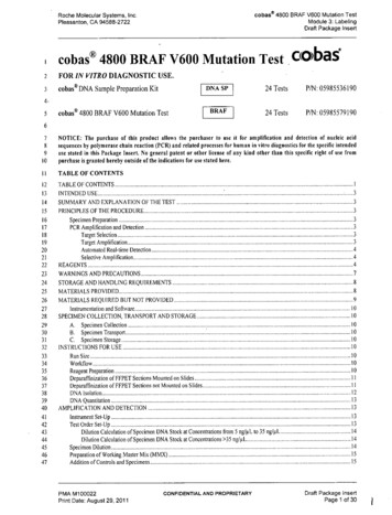
4800 SERIES INSTALLATION MANUAL 1.44800 Series USER CONFIGURED INTERLOCK CONTROLLERThe 4800 series PLC interlock controller is a cost effective method for operating door interlock and mantrap systemswith up to five doors. The fully integrated controller is a one-board solution that gives the user complete control overthe control logic. Doors may be normally locked or unlocked, fail safe or fail secure. They may be selectivelyinterlocked or operated independently of the other doors. Lock relays can be set for either powered or unpowered (dry)contacts.Switches and jumpers are used to configure the controller for the specific application required. No programming skills areneeded. There are three adjustable on-board timing functions. One timer energizes the door alarm relay if a door is proppedopen. Another controls the unlock time when enabled. A third timer controls the time that doors remain unlocked during anemergency egress.The complete system includes a UL 294 Class2 4 Amp 12/24 Volt DC power supply with Fire Alarm Interface in a lockablemetal enclosure.48501 shownFIG. 1AEmergency Unlock InputHDoor Configuration SwitchesORed-Green Traffic Light OutputsBInterlock Shunt InputIOutput Configuration SwitchesPDoor Alarm OutputCDoor and Access Control InputsJLock Control RelaysQPanic Alarm OutputDSD Memory Card SlotKLock Output Wet Dry SelectRLED Output FuseESystem Power InputLLock Control OutputsSDoor Status Out – DryFTimer Adjustment ControlsMLock Power Fuse 2 AmpsTSystem Status LightsGInterlock Setting Switch BlockNLock Ground Return TerminalsUDIN Clip Release Openings (3)Rev 1/18/2019Page 1 of 17
4800 SERIES INSTALLATION MANUAL 1.4OVERVIEWThe 4800 controller allows for any combination of up tofive doors to be interlocked by setting the appropriateswitches.The user may set doors for normally unlocked, lockingonly when an interlocked door is in use, or normallylocked operation, requiring an access control signal tounlock when interlocked doors are secure.There are five lock control relays that can power locksdirectly (wet contact) or operate as dry contact to switchpower by others or for automatic doors.The user may select fail secure (relay energizes to unlockthe door) or fail safe (relay energizes to lock the door)operation.There are five dry contact outputs to mirror door statusback to access control devices when needed.Five powered outputs are provided to illuminate door orlock status red and green LEDs. Locked doors can be setfor either lock status (red when locked, green whenunlocked) or door availability (green when locked butavailable and red when locked but not available becausean interlocked door is in use). Lights for unlocked doorsalways indicate lock status.Rev 1/18/2019Page 2 of 17
4800 SERIES INSTALLATION MANUAL 1.4HOOKUP and MOUNTINGDIN RAIL OR STANDOFFS (U)The DIN rail clips may be used to mount to standard DIN rail track, or standoffsmay be used. The DIN rail allows the installer to make most of the wireconnections with the controller free of the enclosure. When connections arecomplete, the controller snaps onto the track. Use a small screw driver to unclipthe controller. Insert driver through DIN clip release opening (U). Engage the slot,press down and away to release the clip. Repeat for each clip.DOOR POSITION SWITCH (C)Door switch contacts must be closed when the door is closed – the red doorinput LED lights to indicate closed contacts. Twisted pair wiring – AWG gauge22 or larger is recommended for all signal inputs.ACCESS CONTROL INPUT (C)Connect access control output to 4800 REX input. The request for access can be from a card reader, biometric reader,motion detector, pushbutton or any similar device. The lock relay follows the REX input unless the unlock timer is enabled(see timer section for Unlock Pause below). The unlock timer allows the user to determine the unlock period after a valid REX.Inputs are dry contact only. Use an isolation relay for non-dry contact connections (such as a powered output from anintercom). AWG gauge 22 twisted pair or larger is recommended. Use sufficient wire diameter to minimize voltage drop forlong wire runs. Use shielded wire in proximity to sources of interference such as large motors, network servers, and sourcesof electromagnetic radiation.Each door can be set for normally locked or normally unlocked operation using SW2 switches (see below), however if adoor is set as normally locked, it must have closed contacts at the REX input to unlock.LOCK OUTPUT (L)Lock power is switched by the lock relay. The user selects the operation of the lock output, either Fail Safe (lock relayenergizes to lock the door) or Fail Secure (lock relay energizes to unlock the door). User also selects whether the lockpower is supplied by the controller (wet contacts) or by some other source (dry contacts).Rev 1/18/2019Page 3 of 17
4800 SERIES INSTALLATION MANUAL 1.4DOOR LOCKSMag locks and strikes are connected to the designated relay contacts by labeled screw terminals. Relay outputs are either dryor wet contacts. With the jumper in the W position, relay common is connected to V . Lock power is switched directly bythe 4800. Remove the jumper for dry contacts. When relays are operated with wet contacts shorting the output will blowthe fuse and may damage the controller! Lock outputs are individually fused.NOTE: Use a wire of sufficient diameter and rating to minimize voltage drop, especially over long wire runs. AWG 18 or16 gauge is recommended for power circuits. Max current through the relay contacts is 2 Amps. For high currentapplications such as motorized draw bolts, an external high current relay or contactor must be used,AUTOMATIC DOORSAutomatic doors, rollup doors and overhead doors are interlocked by having thecontroller interrupt the OPEN or UP command. Dry contact outputs (no jumper)must be used for automatic doors.TRAFFIC LIGHTS (O)The fused Traffic Light outputs for all doors are powered for direct connection to LEDs. Do not shortany powered output. A single fuse protects the traffic light array from overcurrent and short circuits.Traffic lights for unlocked doors indicate lock status showing green when the door is unlocked andred when the door is locked.Traffic lights for locked doors, indicate door availability status showing green when the door is lockedbut available for use and red when the door is locked but not available because an interlocked door isin use. The user selects either lock status or door status by adjusting the configuration switches foreach door. Note: regardless of the settings, a normally unlocked door will only show lock status.AWG 22 gauge or larger is recommended for signaling and low-power indicator circuits.DOOR ALARM (P)A non-fused relay output is provided for a Door Alarm output. The relay is energized if a lockeddoor is open without a valid REX (forced door), if two interlocked doors are open at the same timeor when the door propped timer is enabled, if the door is open past the user selected time limit.Alarm relay outputs may be used wet or dry. Use wet output to operate an alarm sounder or light.Wet contacts are enabled by moving the jumper to “W”. Do not exceed contact rating of 2 Amps.PANIC ALARM (Q)A non-fused relay output is provided for a Panic Alarm output. The relay is energized if the doorsare unlocked via an active Panic Input. Select wet or dry contacts. 2 Amps max.Rev 1/18/2019Page 4 of 17
4800 SERIES INSTALLATION MANUAL 1.4EMERGENCY UNLOCK (A)The Panic release unlocks all doors regardless of door status for immediate egress in an emergency.Use a maintained contact switch at the terminals shown on the drawing for the system being installed.When actuated, the doors will unlock for as long as the switch contacts remain closed. For a timed panicunlock, see the section on timers below.Note: Panic unlock input can be selected for normally open or normally closed activation. See below.DOOR STATUS OUTPUTS (S)Door Status is provided for connection to Access Control devices or any system that monitors door status.These outputs follow the DPS inputs and are dry contact only. LEDs show when relay is energized (door isclosed). Outputs follow DPS inputs for each door.INPUT STATUS INDICATORS (C)When an input is grounded (closed dry contacts) the input is active. This is indicated by a lighted LED. Theinputs for the 4800 programmable controller are opto-isolated for protection against most kinds ofinterference.Door Position Switches, Magnetic Bond Sensors and similar devices used to signal door status, use theNormally Open contacts so that when the door is closed the contacts are closed.When a door is closed the red input LED for the door will be lighted. This makes it easy to verify interlockoperation and to troubleshoot a new installation. When the door opens, the LED should turn off.For other REX devices such as Bio-sensors, card readers, motion detectors, pushbuttons, pneumaticswitches and the like, the green input LED should be on when the REX is active.LOCK OUTPUT FUSES (M)Lock power relay contacts are fused. If a fuse blows, determine the cause of the overcurrent condition and correct it beforereplacing the fuse. Use the correct quick blow fuse rated at 2 Amps.LOCK RELAY STATUS INDICATOR LED (J)When an output relay is energized, the LED indicator for that relay is on. Magnetic Locks are typically connected to theNormally Closed contacts and electric strikes are connected to the normally open. With the output set for FAIL SECURE,the relay is energized when the door is unlocked. With the output set for FAIL SAFE the door is unlocked when the relayis not energized.For verifying desired operation, compare lighted inputs to the lighted relay indicators.AUTO DOORS WITH LOCKS. – AUX RELAY OUTPUTSFor doors that have locks and automatic openers, the auxiliaryrelay contacts must be used. To access the auxiliary contacts, anoptional wire harness is required. Order part number 4800-AUXHARNESS. The harness connector is pressed onto the three pinheader adjacent to the relay.Use the appropriate relay contacts to interrupt the “OPEN”request, or to signal access control to inhibit the doormechanism. The lock is connected to the fused contacts and maybe set for either wet or dry cooperation.Rev 1/18/2019Page 5 of 17
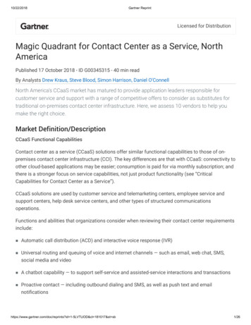
4800 SERIES INSTALLATION MANUAL 1.4BASIC SETTINGSFACTORY DEFAULT SETTINGS – AS SHIPPED Doors 1 and 2 are interlocked. Door inputs for 3, 4 and 5 are jumpered.Lock relays energize to unlock (Fail Secure)Doors are normally unlockedStatus indicators show lock status (green for unlocked and red for locked)Timers are disabled.Panic Input is Normally Open – Panic contacts close to activate emergency unlock.STEP ONE – SET DOOR INTERLOCKSSet the door interlocks first. All interlocks must be reciprocal: if door 1 is interlocked with door 2 then door 2 isautomatically interlocked with door 1. Only one switch is used to interlock both doors. Switches are arranged in blocks bydoor number. D1 Door 1, D2 Door 2 and so on. Above the D1 block are 4 choices, doors 2, 3, 4 and 5. Note that eachblock has one less choice than the previous block to prevent duplication. D2 block does not include a choice for door 1because that is set in the D1 block of switches.1.2.3.4.Select all doors that interlock with door 1 and move the switch for each door to the Y (on) position.Select all doors that interlock with door 2. Remember: if door 1 and door 2 are interlocked, that selection ismade in the door 1 block of switches.Select the rest of the interlocks in a similar manner.If no selection is made, that door will not be interlocked. The controller will ignore the status (open or closed)of any door not selected to be interlocked with another door or doors.EXAMPLE: illustrated right with 4 doors. Door1 interlocks with door 2. Door 3 interlocks withdoor 4. Door 5 is not interlocked and is ignored.If door 1 opens, door 2 locks. If door 3 opens,door 4 locks.Only 2 switches are needed for the interlock.Rev 1/18/2019Page 6 of 17
4800 SERIES INSTALLATION MANUAL 1.4STEP TWO – SET LOCKED OR UNLOCKED OPERATIONEach door must be configured for normally locked or unlocked operation. If an access control input of any kind is requiredto open the door, the door is considered normally locked. This is true for automated doors of any kind, swing doors, rollupdoors, sliders and overhead doors even if they have no locks, but an input is required in order to gain access. An accesscontrol input can be any dry (no voltage) contact closure from a card reader, scanner, pushbutton, motion detector, orremote guard console. The access control input is also called a REX input.If the door does not need an access control input to open, it then is unlocked unless an interlocked door is in use. If a door isselected to be normally unlocked (the factory default) the REX input for that door is ignored.EXAMPLE: In the example at the right, Door 1 islocked. All of the other doors are normally unlocked.All lock outputs are FAIL SECURE meaning that therelay energizes to unlock the door.STEP THREE – SET LOCK RELAY FOR FAIL SAFE OR FAIL SECUREThe factory default is for Fail Secure lock relay operation. This means that the relay energizes to unlock the door.Typically, mag locks are connected to the normally closed relay contacts and strikes bolts are connected to the normallyopen contacts. For other lock types connections may vary. Check manufacturer’s recommendations.If FAIL SAFE operation is required, move the switch for each door to the in the Door Configuration switch block to theFail Safe position (on). See illustration above.STEP FOUR – SET WET OR DRY LOCK OUTPUTSLock outputs can be either wet (supply positive voltage at the output) or dry (no voltage at the output). To use theDortronics power supply to directly power the door locks, select wet operation by installing a jumper. To have the relayswitch lock power from another source, remove the jumper. With jumper removed or in the dry (D) position, the outputis dry.Rev 1/18/2019Page 7 of 17
4800 SERIES INSTALLATION MANUAL 1.4OPTIONAL FUNCTION SETTINGSSET WET OR DRY ALARM OUTPUTSThere are two alarm out relays.The Door Alarm relay. It is energized if a locked door is open without a valid REX, if two or more interlocked doors areopen at the same time, or if a door is propped open when the door prop alarm timer is set.The Panic Alarm relay is energized when the Emergency Unlock input is active or the unlock timer is running.The alarm relays can be used to power sounders, strobes, or other powered indicators directly by installing the wet outputjumper. For dry output to signal other monitoring stations, be sure the wet/dry select jumper is removed.SET TIMER FUNCTIONSThere are three onboard timer functions: Door Propped Timer; Unlock Pause Timer; Interlock Timer. Eachtimer is enabled by moving the appropriate switch to GO and disabled when the switch is set to NO.PROPPED DOOR TIMERThe Door Propped timer, when enabled, begins timing as soon as any door is open. If the door is openwhen the timer expires, the door alarm output relay energizes. Use the rotary control to set the time delay toany value between 2 seconds and 2 minutes.EMERGENCY UNLOCK TIMERThe Interlock timer, when enabled, begins timing when the Emergency Unlock input is activated. All doors remainunlocked and automatic doors remain enabled until the timer expires. Set to any value between 2 and 60 seconds.Emergency unlock overrides System Pause and unlocks all doors. Door/lock lights go green.UNLOCK PAUSE TIMERThis is typically used when a momentary REX device is located some distance from the door. The timerallows the user time to get to the door and open it after making the request for access. The Pause timer,when enabled, determines the time a locked door remains unlocked after a valid request by access control, apushbutton, motion detector or similar device. This only applies to doors that are set as normally locked. Usethe rotary control to adjust the unlock time between 1 and 30 seconds.SET DOOR INDICATION LIGHTSDoor light outputs are available to let the user know when a door may be opened. Normally unlocked doorsuse lock status indicators where green indicates the door is unlocked and red indicates that the door is locked.Normally locked doors use either lock status or door status where green indicates that the door is ready to beunlocked and red indicates that the door is not ready to be unlocked because another door is in use.Either lock status or door status can be selected for each door by setting the R/G DIP setting.As shown at right, the door indicator lights can beset for either lock status or door status. In theexample shown, door 1 is normally locked and thedoor lights indicate door status. Doors 2, 3, 4 and 5are normally unlocked and the door lights indicatelock status - locked or unlocked.Rev 1/18/2019Page 8 of 17
4800 SERIES INSTALLATION MANUAL 1.4SET EMERGENCY UNLOCK INPUT FOR NORMALLY OPEN OR NORMALLY CLOSEDThe emergency unlock feature (Panic) allows for all doors to be unlocked regardless of interlock status foras long as the input is true. The input can be set to unlock all doors on either a make (N.O.) or break (N.C.)of the emergency unlock circuit. If pull boxes or any similar series connected switches are used, the Panicinput should be set to normally closed (N.C.). If pushbuttons, or alarm circuits with parallel connections areused, Panic should be set to normally open (N.O.) as shown above.OTHER FEATURESINTERLOCK BYPASS - SHUNTThe 4800 controller allows for the interlock logic to be bypassed when desired. This feature istypically used to allow unrestricted access at certain times of the day, or to allow formaintenance or cleaning service to open more than one door at a time for the movement ofmaterials, or equipment.Connect a normally open maintained contact switch (typically a keyed switch, but a card reader,keypad or other secure input device could be used) to the SHUNT input. The interlock functionis disabled for as long as the shunt switch contacts are closed. Any normally locked doorsremain locked and must be opened by means of the normal access control sequence, howevermultiple doors normally interlocked may be open at the same time.No interlock alarm is generated as long as the SHUNT is active, however a forced door (a locked door open without a validREX) will still result in a door alarm.SYSTEM STATUS LIGHTS (L)POWER (PWR)The power status light glows green whenever the 4800 is connected to 12-24 VDC.WATCHDOG LED (WD)The PLC is continually monitored by a watchdog function. The watchdog LED blinks rapidly (at a rate of 3times per second) to indicate that a program is loaded and is being executed correctly.TIMER LED (TMR)The timer light indicates that one of the three timers is running. If the Panic light is also lit, the emergencyunlock timer is running. It is important to check the timer light if the system is not responding to otherinputs. The System Pause timer and the Panic timer while running will ignore requests for access. If a timerhas been set inadvertently, make sure the timer “GO – NO” switches in SW3 are set to “NO”PANICA lit Panic LED indicates the Panic input or the emergency unlock timer is active. All doors remainunlocked until the timer expires or the input is reset.ALARMA lit Alarm LED indicates either a door alarm or an emergency unlock alarm.BUSYThe Busy LED is lit when the system is not idle: a door is in use; a timer is running; or there is an alarm condition.IDLEIdle light indicates that the system is monitoring all doors and requests for access. None are active. No alarms are active.No timers are running.Rev 1/18/2019Page 9 of 17
4800 SERIES INSTALLATION MANUAL 1.4TROUBLE SHOOTING THE INSTALLATIONVisual indication of all inputs, outputs and system status is provided for verification of all conditions andsettings. If the installation does not operate as desired, check the following in the sequence shown:NOTHING WORKS1.POWER LIGHT - The controller requires 12 – 24 VDC to operate. Verify the green POWER LED is lit. If not:a.Check the power supply connectionsb.Check the power supply output terminalsc.Check the Power Supply fused.Check the Mains connection and the fuse at the 110 VAC terminal.2.WATCHDOG LIGHT - If power connections are correct and the POWER LED is lit, verify that the WatchdogLED is blinking at a constant rate of 3 blinks per second. If it is not blinking, call Dortronics Technical Assistance.3.DOOR INPUT LIGHTS - Verify that each door that is to be interlocked by the controller is closed and that theinput LED for each interlocked door is lighted. Unused door inputs can be jumpered out if needed.If it is not possible to keep the doors closed while troubleshooting because the facility is in use, temporarily jumpthe door inputs for all interlocked doors. Use a short piece of wire as a jumper. Jumper unused door inputs as well.4.5.6.REX INPUT LIGHTS – For Locked Doors Only:a. Verify that no REX inputs are active and that no rex input lights are lit.b. Make sure door is correctly configured. Verify that the door configuration switch is correctly setto “LOCKED” position for the door being tested. If it is set to unlocked, the REX input isignored.c. To test a REX input, use a short piece of wire to jump the two REX input terminals. Verify thatwhen a designated REX input is active, the corresponding lock relay changes state (shown by the relayLED for the lock relay being tested). Door 1 REX operates Door 1 lock and so on.LOCK RELAY “ON” LIGHTSa. When the system is IDLE and the idle light is on, verify that all normally unlocked fail secure doorsshow a lighted (energized) relay.b. Are the relays on when they are supposed to be?c. Verify that all normally locked fail secure relays are not energized (relay LED is off).d. For Fail Safe settings, the relays should be ON when locked and off when unlocked at idle.If the relays do not reflect the desired state check:a. The door configuration is correct for the desired operation.b. The door position inputs for all doors in the interlock are closed – the input LED is on.c. That no REX inputs are active – REX LEDs are all off.Make sure the doors are correctly set for the desired operation. For anormally locked door set switch corresponding to the door to the “on” or upposition. For Fail Safe lock operation, set the switch corresponding to thedoor in the up or “ON” position.NO LOCK POWER1.2.3.Check the lock relay fuse.If the controller supplies power to the locks check that the jumper is on the Wposition. Use a multi-meter to verify that lock relay common is at the supply voltage.Check that the lock is connected to the correct output. For Fail Secure operation themag lock connects to N.C. contacts. Strikes connect to N.O. contacts.Rev 1/18/2019Page 10 of 17
4800 SERIES INSTALLATION MANUAL 1.4STAYS IN DOOR ALARM1.2.Check that all interlocked doors are closed - door inputs are “ON”. If there is any doubt that a door position switchis operating correctly, use a piece of wire to jumper the input. Remember: DPS inputs show red and REX inputsshow green input LEDs.Check that the Panic (emergency unlock timer) is not set and running. System Idle light should be lit.DOOR LOCKS WHEN IT SHOULD UNLOCK1.2.Make sure the lock is connected to the correct contacts on the lock relay. Some locks can be set for either Fail Safeor Fail secure operation. Make sure the lock type matches the controller lock logic. The lock relay is energizedwhen the door is unlocked when Fail Secure.Check that the Fail Safe – Fail Secure setting is correct for the application.DOORS REMAIN UNLOCKED AT ALL TIMES1.Check Panic relay and System Status Panic light. If they are on, check that the Panic N.C. – N.O. switch (SW3) is setcorrectly. If the switch is set to N.C. and there is no Panic input, the doors will remain unlocked. If the switch is set toN.O. and the panic input is closed (light is lit) the doors will remain unlocked.If Panic output is lit and thereis no connection at the Panicinput, the Panic input is set toN.C. – change setting to N.O.Rev 1/18/2019Page 11 of 17
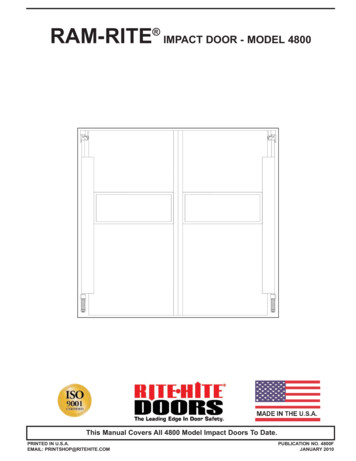
4800 SERIES INSTALLATION MANUAL 1.4SOME EXAMPLES4 DOORS UNLOCKED5 DOOR LOCKEDRev 1/18/20194 maglocks with powered outputs for fail secure operation. No timers selected. R/G lights show lockstatus. All doors interlocked. If any door opens the others lock. Doors normally unlocked5 maglocks with powered outputs for fail secure operation. No timers selected. R/G lights show door status. Alldoors interlocked. If one opens others are inhibited. Doors normally locked. Door status output to access control.Page 12 of 17
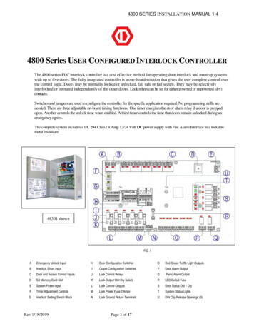
4800 SERIES INSTALLATION MANUAL 1.43 DOORS 1 LOCKED 1 SHARED3 doors, 1 locked. Door 2 is shared. If 2 is open 1 and 3 are not available. If 2 is closed 1 and 3 can be used at the same time.Prop timer is set to alarm if any door is open beyond selected time limit.INTERLOCK TABLEDoorLocks1221, 3324Not Used5Not Used4 DOORS 2 MAN, 2 ROLLUP, 1 LOCKED4 doors, 1 locked. Doors 1 and 2 are man doors with strikes. Doors 3and 4 are rollups. If any door opens, others are not available.Rollup door UP command is interrupted by dry contact output. Door alarm is a sounder using wet contacts.INTERLOCK TABLEDoorLocks12, 3, 421, 3, 431, 2, 4,41, 2, 3,5Not UsedRev 1/18/2019Page 13 of 17
4800 SERIES INSTALLATION MANUAL 1.45 AUTOMATIC DOORS WITH MAG LOCKSFor doors with automatic openers and locks, an optional auxiliary output is required, part number 48500xAUX or 48501xAUX. The option allows theuser to access a second set of contacts on each door control relay. As shown below, the primary contacts switch lock power and the secondarycontacts mirror the REX input out to the auto-door opener. When an interlocked door is in use, the output does not change state.Rev 1/18/2019Page 14 of 17
4800 SERIES INSTALLATION MANUAL 1.4POWER SUPPLY SPECIFICATIONSThe 4204NX power supply/charger converts a 120VAC 60Hz input into a single PTC protected Class 2 powerlimited output. Output is selectable for 12VDC or 24VDC with a total of 4A max. It also offers a suite of featuresthat includes fire alarm disconnect, overvoltage protection, and low power disconnect which prevents deepdischarge of stand-by batteries.InputFire Alarm DisconnectVoltage 120VAC, 60Hz, 3.5A max.Fusing 5A / 250V.Supervised Latching or non-latching.EOL 10K Resistor.OutputsVoltage 12VDC or 24VDC selectable.Current 4A continuous max.Protection Fused 2.5A / PTC 2A.Auxiliary Class 2 power-limited @ 1A (unswitched).Other Overvoltage protection.Filtered and regulated.SupervisionAC Failure Form “C” contacts.Battery Form “C” contacts.Low DC Power ShutdownShuts down DC output terminals if battery voltagedrops below 71-73% for 12V units and 70-75% for24V units to prevent deep battery discharge.Back-up Battery (not included)Capacity 7AH / 12VDC (1 or 2 within enclosure).Type Sealed lead acid or gel type.Fuse Rating 5A @ 32VDC.Failover Upon AC loss, instantaneous.Indicators (LED)Input 120VAC is present.DC Output Powered.Battery Discharged or not connected.CONTROLLER SPECIFICATIONSQtyPower InDescriptionRemarks12 or 24VDC regulated - plus, common and earth ground3 - Screw TerminalsInputs125 DPS, 5 REX, 1 Panic and 1 ShuntScrew TerminalsOutputs155 Fused Lock Relays, 5 Door Status Out, 5 R/G Light Powered OutputsScrew TerminalsTimers3Single Turn Rotary Adjusters to set Time DelayTemperatureOperating 0-60 CMountingDIN Rail Clip or StandoffsDimensionsFuses6”W x 10”L x 1 ¾” H – with DIN Clip installed. 1 ¼” H without62 Amp @ 250 Volts – quick blowCurrent Draw ‐ ConditionController onlywith all relays on – all indicator lights litCurrent in mA70250Controller onlywith all relays on ‐ all indicator lights litRev 1/18/201950160Page 15 of 17Volts12122424
4800 SERIES INSTALLATION MANUAL 1.4RECOMMENDED EQUIPMENTDORTRONICS PART#DESCRIPTIONDortronics #1110xDxBDortronics #7201xL2-HDortronics #7202xL2-HxCS1200 lb electromagnetic 12/24 VDC maglocks with built-in door position and bond sense switches.High intensity Red / Green LEDs on single gang S/S wall plate.High intensity Red / Green LEDs with Piezo sounder on double gang S/S wall plate.(Optional for use with security breach alarm output.)Panic mushroom switch latching push, pull.Dortronics #5216 MP23PP/RXE2SALES ‐ WARRANTIESContact:800-906-0137Mike Palermo – Sales/Customer ServiceSales/Applications Specialist Bryan Sanderford ‐ National Sales ManagerContact (Technical): Stuart ArthurJoe Hanna – Engineer/Applications SpecialistProduct Warranties:All electromagnetic locks have a LIFETIME GUARANTEE against defects in material and workmanship.Defective units will be replaced or repaired based upon incoming evaluation and inspection.All other Dortronics components of the Electric Locking System shall be similarly warranted for a period of oneyear. Expressed warranties are conditionally based on the requirement that the items covered within theguarantee are used and maintained in accordance with the manufacturer's recommendations.A Return Authorization Number must be obtained and accompany all returns within 14 days of issue. Unuseditems returned for credit must be complete and packed in original unit box and are subject to a 15% restockingfee. Any shipping or order discrepancies must be reported within 5 days of receipt.Rev 1/18/2019Page 16 of 17
4800 SERIES INSTALLATION MANUAL 1.4INSTALLATION AND OPERATION NOTESINTERLOCK SCHEDULE FORDoor IDDoor Use12345Prohibits DoorsDate / /Rev 1/18/2019INTERLOCK SCHEDULE FORDoor IDDoor Use12345Date / /Page 17 of 17Prohibits Doors
One timer energizes the door alarm relay if a door is propped open. Another controls the unlock time when enabled. A third timer controls the time that doors remain unlocked during an emergency egress. The complete system includes a UL 294 Class2 4 Amp 12/24 Vo lt DC power supply with Fire Alarm Interface in a lockable metal enclosure. FIG. 1