Transcription
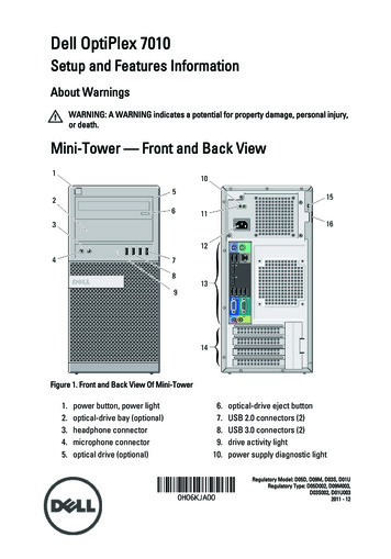
Tutorial: Designing a Simple Optical System in LightToolsLiliana Ruiz DiazDecember 08, 2016College of Optical Sciences, University of Arizona, Tucson, AZ USA 857211.1 Introduction: What is LightToolsLightTools is a 3D optical design software that supports virtual prototyping, simulation,optimization, and photorealistic renderings of illumination applications. This is a non-sequentialsoftware that allows to create and modify illumination system designs and allows for furtheroptimization [1].1.1.1 Sequential vs non-sequential raytracingNon-sequential ray tracing is fundamentally different than a sequential mode. In this mode raystravel from source to detector, regardless of the optical elements position and sequence. Some keydifferences between these modes [2] are:Sequential mode-Mainly used for designing imaging and afocal systemsRays only intersect each surface once and they follow in specified sequential orderEach surface has its own local coordinate systemNon-sequential mode-Primarily used for non-imaging applications such as illumination systems and/or stray-lightanalysisYou can import mechanical components from CAD programsA ray can intersect the same object more than once and can intersect multiple objects inany orderEach object is referenced to a global coordinatePartially reflected rays can be generated and traced from a refractive interface, in additionto tracing the refracted ray1.2 LightTools Interface ElementsThe software runs in a 3D Design window containing several tabs and toolbars (Figure 1). Theseinclude the System Navigator, Preferences Navigator, Window Navigator, and Output windowwhich are by default docked. In this tutorial, you will mostly use the System Navigator and menu.Moreover, the 3D Design view is where the design is built. This is an interactive graphics windowsimilar to other CAD mechanical software. The 3D Design view has available several commandsas shown in Figure 2. In this tutorial, all those commands will be used except the command line.
Liliana Ruiz Diaz – LightTools TutorialFigure 1. Menus and tabs in LightTools, image taken from LightTools tutorial documentation [3]Figure 2. Commands and Toolbars in LightTools, image taken from LightTools tutorialdocumentation [3]Page 2 9
Liliana Ruiz Diaz – LightTools Tutorial2.1 Basic optical setupIn order to ray trace in LightTools you need to have at the very least a source and a receiver. Theoptical elements (lenses, prisms, mirrors, etc) can be placed anywhere regardless of the detectorand source direction and position. In this tutorial you will use a plano-convex lens to collimatelight from a point source and learn how to analyze the collimation with a detector.2.2 Inserting the sourceThere are many ways to add a light source in your system. The easiest way is to open the inserttab and click in Light Source (Figure 3) from the main top menu. This will open another tab whichcontains several options to create a source. For this tutorial, select Point and click anywhere in theLightTools window. A source will be created. Right click on the source to open the propertieswindow of the source. In this window you can customized your source, including location andillumination properties. For this tutorial, make sure your source is located at the origin. Also select100 watts for radiometric power and aim area, for aim region. Click Apply and an Aim Area tabwill appear, modify the aim area to have a diameter of 20 mm and coordinates of (0, 0, 40).Figure 3. Inserting source directions and point source window propertiesPage 3 9
Liliana Ruiz Diaz – LightTools Tutorial2.3 Inserting the receiverSimilarly to the light source case, there are multiple ways to create a detector. A common way isto create a solid object and then add a detector on one of its surfaces. Click in the Mechanicaloption from the Command palette to create a block by clicking in Draw Block. Proceed to drawthe solid in the LightTools Window (Figure 4). Modify the solid properties to have 2x30x30 mmdimensions (length, width, and height, respectively) and place it 60 mm away from the source inthe z-direction.To add the receiver, click on the Insert tab and click in Receiver. Select the Surface option andclick on the front face of the cube. This will generate a detector which can be accessed through theSystem Navigation under the Illumination Manager tab.Figure 4. Inserting a block directions and adding a surface receiver directionsPage 4 9
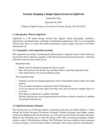
Liliana Ruiz Diaz – LightTools Tutorial2.4 Creating a lensSelect the Lens option from the Insert tab to create an ideal thick plano-convex lens (Figure 5).For this tutorial, select Spherical lens and draw the lens anywhere in the LightTools window. Thelens properties can be accessed through the System Navigator under the Components tab. Bydefault, the lens material is NBK7, change it to B270 which is located in the Schott Catalog underthe Material tab. Modify the lens to have thickness equal to 6mm, a diameter of 25.4mm, and aposition equal to (0,0,45). Click on Lensfrontsurface and modify the curvature of the front lenssurface to 0.05 m-1, make sure that the convex option is selected. Finally click in Apply, the planoconvex lens should be positioned between the point source and detector. The focal length andprincipal planes will be calculated automatically and are visible under the Lens Primitive tab.Figure 5. Inserting a lens directions and spherical lens window propertiesPage 5 9
Liliana Ruiz Diaz – LightTools Tutorial3.1 RaytracingThere are two ways to trace optical rays. The first method is by clicking in the Ray Trace tab andselect Begin All Simulations. This will show your point source generating rays towards your squaredetector as in Figure 6. If you need to increase the number of rays trace/shown, click on SimulationInput instead and modify the forward simulation as needed. When you finish, click on BeginForward Simulation to start ray trace.A second and faster way to ray trace is by clicking on exclamation symbol located at the Toolbar.However, you will not able to change the number of rays that are simulated.Figure 6. Ray trace directions and simulation propertiesPage 6 9
Liliana Ruiz Diaz – LightTools Tutorial3.2 Collimating the light sourceIn the Simulation window you will see that light is not fully collimated (Figure 6). This occursbecause the light source is not placed in the back focal length (BFL) of the lens. In order tocollimate the light from your point source, copy the BFL from the lens property window andchange the z-axis position of the lens to match this number. The new simulation will be similar toFigure 7.Figure 7. Correcting lens position to collimate light4.1 Detector AnalysisThe last part of this tutorial is to demonstrate how to use the detector to analyze your optical system.Click on the Analysis tab and select the Illuminance Display, then select the LumViewer (Figure8). Since there is only one receiver in your optical design the LumViewer will automaticallydisplay the measured irradiance from the receiver that you designed.Page 7 9
Liliana Ruiz Diaz – LightTools TutorialFigure 8. Directions to display detector informationThe irradiance shown should be similar to the one displayed in Figure 8, which is the flux detectedby the front surface of the block. If the lens would be ignored/eliminated, for instance, the red areawould be larger. You can also rotate the lens and observe changes in the irradiance pattern.In order to increase the number of pixels in the receiver, select the Illuminance Mesh tab under theForward Simulation for the receiver properties, this can be accessed from the System Navigator(Figure 9). This will open the detector property windows and you can improve the resolution byincreasing the number of bins. This will allow you to observe more features. Notice that a largenumber of bins requires a higher number of traced rays as noise starts being more noticeable.Page 8 9
Liliana Ruiz Diaz – LightTools TutorialFigure 9. Increasing the number of pixels increases the resolution but also noise is increased.References[1] LightTools Features feature-details.html[2] Exploring Non-Sequential Mode in max[3] LightTools Introductory Tutorial - Version 8.3 June 2015Page 9 9
- Primarily used for non-imaging applications such as illumination systems and/or stray-light analysis - You can import mechanical components from CAD programs - A ray can intersect the same object more than once and can intersect multiple objects in any