Transcription
Tankless Water Heaters
How a Tankless operatesWhen a hot water fixture opens, theflow of water causes the flow sensorimpeller to spin. The larger the flowrate, the faster the impeller spins.The computer board reads how fast theimpeller is spinning to determine theflow rate.Once the activation point (0.5 gpm onmost current models) is met, thecomputer board moves on to the nextstep.
How a Tankless begins ignitionIn preparation for combustion, thecomputer tells the fan motor toinitiate. The fan sends a signalback to the computer board tosignal that it is operating at thecorrect RPM, without blockage.
Tankless ignition processNext, the computer gives power tothe igniter, which starts a spark in thecombustion chamber.The main gas valve and solenoidvalves open to let gas into thecombustion chamber.
Tankless ignition processWith the precise amount ofcombustion air and gas for a cleanburning flame, combustion occurs.The flame sensor, located within thecombustion chamber, verifies thatcombustion has occurred.
Tankless combustion processAfter combustion has started, thecomputer board constantly utilizesinformation from a number of sensors inorder to determine how much air andgas is needed for the desired settemperature, and modulatesaccordingly.These sensors include three thermistors(reading the inlet, outlet, and heatexchanger temperatures) and the flowsensor.The AFR (air fuel ratio) rod is anothersensor inside the combustion chamberthat measures the quality of thecombustion, ensuring that it is a strong,blue, low COx producing flame.
Tankless combustion processUsing all the sensors, the computercontrols the components thatmanage the air, gas, and water flowamounts to meet the varying levelsof demand it encounters from thehot water fixtures.The bypass valve (BV) mixes coldwater into the outgoing hot line toreduce pressure loss, and increasespeed of modulation.A proportional gas valve (notpictured, but between main valveand solenoids), manages theamount of gas delivered to thedifferent sections.
Components
Burner AssemblyT-M32 BurnerFacilitatescombustion:4 stagesThe burnerassembly iscomprisedof two typesof burners:rich and leanThe assemblyfacilitatesproperair/fuel ratiosfor propercombustionTwentyT-M32Burners
Burner AssemblyGeneralmodes offailure:Possibleeffects offailure:Basicdiagnostics: Dust or soot deposits either on theburner surface or inside the burnerassembly Gas leaks due to compromised gaskets Unstable flame conditions and/or flame loss Ignition failure Improper combustion / high emissions Remove assembly from combustionchamber and perform a visualinspection of the burner.
Gas ManifoldManifold isdivided into 3zones,creating 4stagecombustion1 0 - 3 / 4 " ( 2 7 6 .4 m m )7 - 7 / 8 " ( 2 0 2 .6 m m )Distributesgas into thecombustionchamberTwo sets of gasnozzles: one setprovides to thelean burnersand the otherset provides tothe richburners
Gas ManifoldGeneral modesof failure: Dust deposits on the manifold Gas leakage from failed gasketsPossibleeffects offailure: Unstable flame conditions and/orflame loss Ignition failure Improper combustion / highemissionsBasicdiagnostics: Remove gas manifold perform avisual inspection for excessivedust deposits around the nozzles.
Fan MotorExhausts fluegases6 - 1/ 2 " ( 1 65 .5 m m)Providescombustion airinto the burnerchamber2-1/83-3/4"(95.15mm)"(54mm)
Fan MotorGeneral modesof failure: Improper fan motor speed Moisture on the electricalconnections of the fanPossibleeffects offailure: Inability for water heater to function Ignition failure Improper combustion / highemissions Abnormal sounds prior to, during,and after combustionBasicdiagnostics: Visual inspection of electricalconnections to fan motor:moisture, dust,connection/breakage of wires Visual inspection of fan motorhousing for moisture Voltage check (Service Manual) Fan speed check (Service Manual)
Gas Valve AssemblyOpens and closes thegas pathways goinginto the manifold andcombustionchambers (main andsolenoid valves)Modulates theamount of gas goinginto those chambers(proportional valve)4 - 1 / 2 "( 1 1 4 m m )4-1/2(119mm)
Gas Valve AssemblyGeneralmodes offailure: Damaged housing or O-rings causinggas leaks Inability to open/close (main andsolenoid valves) Inability to properly modulate(proportional valve)Possibleeffects offailure: Inability for water heater to function Ignition failure Improper combustion / high emissions Abnormal sounds during combustion Lack of water temperature controlBasicdiagnostics: Visual inspection of electrical connections: moisture,dust, connection/breakage of wires Listen for the double “clunk” sounds from the gasvalves right after fan motor initiates during start ofoperation. Voltage & resistance check (Service Manual)
Flame SensorSensing elements(AFR & flamesensors)Detectswhethercombustionhas occurredduringoperationEnsures thatcombustion isnot occurringwhen thewater heatershould be offAssembledwith the AFRsensor (somemodels)Connection leadsto the PCBFlamerodAFRRod
Flame SensorGeneralmodes offailure: No detection of flame whencombustion has occurred. False detection of flame whenno combustion has actuallyoccurred.Possibleeffects offailure: Water heater will stopoperatingBasicdiagnostics: Visual inspection of electricalconnections: moisture, dust,connection/breakage of wires Electrical current check (ServiceManual)
AFR SensorSensing elements (AFR &flame s areless thanideal,computeradjusts fanmotor n thechamberConnection leadsto the PCBFlameAlsofunctions asa secondaryflame sensor(verification)rodAssembledwith theflamesensorAFRRod
AFR SensorGeneralmodes offailure: No detection of flame whencombustion has occurred. False detection of flame when nocombustion has actually occurred.Possibleeffects offailure: Water heater will stop operating Fan motor cannot adjust properlyin response to abnormalcombustion conditions. Improper combustion / highemissionsBasicdiagnostics: Visual inspection of electricalconnections: moisture, dust,connection/breakage of wires Electrical current check (ServiceManual)
Primary Heat ExchangerAbsorbs heatfromcombustionTransfers thisheat into thewater
Heat ExchangerGeneralmodesoffailure:Possibleeffects offailure:Basicdiagnostics: Exhaust gas leakage Clogged heat exchanger fins Breach in drum walls Hard-water scale Heat stress Corrosion Copper damage due to heat stressWater leakagePoor heat transferAbnormal combustion noise Visual inspection: soot, debris, cracks,water leakage, scale buildup, etc.
Secondary Heat gnostics:Transfers thisheat into thewater Visual inspection: soot, debris, cracks,water leakage, scale buildup, etc.
Flow SensorDetects andmeasures thewater flow rateContains aspinningimpeller andmagnetic pickup
Flow sensorGeneral modesof failure: Impeller does not spin or spin freely:unable to detect or measure water flow.Possible effectsof failure: Startup ignition sequence willnot initiate. Water heaterwill not operate.Basicdiagnostics: Visual inspection of electricalconnections: moisture, dust,connection/breakage of wires Visual inspection of impellerfor debris (any cause ofrestriction) Voltage check (ServiceManual)
Water Control ValvesProvides 3 functions within the water heater: flow adjustment, bypass, and two-way functions (540)Controls water flow to maintain proper output water temperatures (flow adjustment function)Mixes hot and cold water for proper output water temperatures (bypass function, 540 only)Prevents low-temperature corrosion from condensation in the heat exchanger (bypass function)Prevents water flow through the heat exchanger when water heater is not in operation (two-way function)
Water Control ValvesGeneralmodes offailure:Possibleeffects offailure:Basicdiagnostics: Breach in valve housing, causing water leakage Inability to modulate flow or make fullyopened/closed positions Water leakage can damage other componentsof the water heater Fluctuation in hot water output temperatures Visual inspection of electrical connections:moisture, dust, connection/breakage of wires Visual inspection of valves: motor drive lockeddue to scale buildup, breach in housing, etc. Voltage check (Service Manual)
Water ThermistorsThermistors measureand help monitor watertemperaturesthroughout the waterheaterThere are 3 (540)240,340 have 2 waterthermistors : one for theincoming cold water, onefor the heat exchanger,and one for the output240/340 Thermitors540 Thermistors
ThermistorsGeneralmodes offailure: Open circuit failure (no current) orelectrical short (no resistance) Resistance values are off thecalibrated valuesPossibleeffects offailure: Water heater will not operate Fluctuation in hot water outputtemperaturesBasicdiagnostics: Visual inspection of electricalconnections: moisture, dust,connection/breakage of wires Visual inspection of thermistor:damage, buildup of debris or scale,etc. Resistance check (Service Manual)
Hi-limit switchDetectsexcessivelyhigh watertemperatureswithin theheatexchanger.Upondetection,immediatelycuts off allpower to thegas valves.Utilizes bimetalthermalexpansionManual resetswitchReset button
Hi-limit switchGeneral modes offailure: Open-circuit or closed-circuit failuresPossibleeffects offailure: In a closed-circuit failure, switch cannotdetect high water temperatures. Thethermistors will then act as backup hi-limitdetectors until operation ends. If an open-circuit failure, water heater will notoperate.Basicdiagnostics: Visual inspection of electrical connections:moisture, dust, connection/breakage of wires Visual inspection of the switch: position of thereset button (pressed or depressed) Possible buildup of scale within the heatexchanger. Voltage/resistance check (Service Manual)
Exhaust Safety Features1Thermistor,can gettemp readout oncontroller140 Exhaust Thermistor1 Flat platehigh limit,automaticreset 151 Protectstemps forgetting over140 If one fails,system willread anerror, andunit willshut downFlat plate High Limit
Overheat Cutoff FuseDetects excessivetemperaturesaround the heatexchanger andcombustionchamber.Upon detection,immediately cutsoff all power tothe gas valves.Fuse containssolder, with amelting point of430 F.31-1/2"(800mm)
Overheat Cutoff FuseGeneral modes offailure:Possibleeffects offailure:Basicdiagnostics: Open-circuit or closed-circuitfailures In a closed-circuit failure,excessive heat can cause abreach in the walls of the heatexchanger or combustionchamber. In an open-circuit failure, waterheater will not operate. Visual inspection of electricalconnections: moisture, dust,connection/breakage of wires Voltage/resistance check (ServiceManual)
Freeze-Protection ThermostatSenses ambient air temperatures and activates thefreeze-protection ceramic heaters when necessaryCeramic heaters activate when the thermostat sensestemperatures below 36.5 F7 / 8 " ( 2 2 .2 m m )1 - 3 / 8 " ( 3 3 .5 m m )1 / 4 " ( 5 .7 m m )
Freeze-Protection Ceramic HeatersThe ceramic heatersprevent water withinthe water heater fromfreezing during nonoperation. Freezingcauses water to expandand can rupture theheat exchanger andother componentsThe ceramic heatersare located throughoutthe water heater alongthe water pathways
Freeze-Protection Ceramic HeatersGeneralmodes offailure: Open-circuit failures:ceramic heaters do notreceive the voltageneeded to heat upPossibleeffects offailure: Freezing cannot be prevented,heat exchanger may burstfrom excessive pressure.Basicdiagnostics: Visual inspection of electricalconnections: moisture, dust,connection/breakage of wires Voltage/resistance check (ServiceManual)
Computer BoardControls most of the functions of the water heater8-1/8" (205.76mm)1-9/16" (39.51mm)5-7/8"(129.39mm)
Computer BoardGeneral modes offailure:Possibleeffects offailure:Basicdiagnostics: Computer board malfunction Lack of proper combustion controlduring operation Inability to detect signals fromnumerous sensors Lack of water temperature control Error in self-diagnostics No communication between heatersor with the controller in a multipleunit manifold system. General abnormal responses Visual inspection of electricalconnections: moisture, dust,connection/breakage of wires Visual inspection of PCB e.g. burnmarks or brown spots
IgniterCreates a spark to ignite the air/fuel mixture withinthe combustion chamber during activationThe output voltage of the igniter exceeds 14 kV.To High valtageignite cablePower supplyAC 90 to 110V
IgniterGeneralmodes offailure: Unable to create a spark (oradequately strong spark) duringactivation Continually creates sparks i.e.before, during, and after operation.Possibleeffects offailure: Without ignition, water heater willnot operate Durability of igniter will decreaseBasicdiagnostics: Visual inspection of electricalconnections: moisture, dust,connection/breakage of wires Observe spark condition: strong,blue, & solid vs. weak. Voltage check (Service Manual)
Freeze-Protection ThermostatGeneral modesof failure:Possible effectsof failure:Basicdiagnostics: Closed-circuit failure Open-circuit failure In a closed-circuit failure, ceramicheaters will always remain on,providing excessive heat in the longterm. In an open-circuit failure, the waterheater’s freeze-protection systemwill never activate, causing damagesassociated with freezing water Visual inspection of electricalconnections: moisture, dust,connection/breakage of wires Visual inspection of thermostatbody Voltage check (Service Manual)
Fuse BoxProtects water heater from high voltage and/or currentcaused by lightning or other electrical spikes or surgesFuse box contains two surge absorbers: Absorber A activateswhen voltages exceed 220 volts. Absorber B activates whenvoltages exceed 680 volts.Fuse: 10ASurge absorber B: 680V
Fuse BoxGeneral modesof failure: Short-circuit failure of absorber Open-circuit failure of absorber and/or fusePossibleeffects offailure: In a short-circuit failure of the absorber, thefuse will blow out and the water heater will notoperate. Inability to protect the computer board in theevent of high-voltage surges. A damaged boardwill stop all water heater operations.Basicdiagnostics: Visual inspection of electrical connections:moisture, dust, connection/breakage of wires Visual inspection: burn marks on the components Voltage check (Service Manual)
Installation Requirements
BASIC INSTALLATION REQUIREMENTS Specifications: Always size gas line for maximum BTU rating for yourheater or heaters. Gas: ¾” – 1” ID Gas Line Minimum, Use BTU Chart Water: Treated water to extend the lifespan of heat exchanger Water connections: ¾” -1” recommended with isolation valves. Recommended 30 80psi water pressure Electrical: 120VAC Electrical Supply, No dedicated or GFI circuitneeded(check with local codes) Make Up Air: Clean combustible air supply recommended Cat. III Stainless Steel Only, Exhaust Vent Pipe on Non-Condensing Units
GasUse National Fuel Gas code chart for pipe capacities (NGand LP WC)
Water Quality
Water Quality Hard water will shorten the life of the heater– Residential: 7 grains/gal (120 ppm) max– Commercial: 4 grains/gal (70 ppm) max Isolation Valves are recommended Flushing/Descaling– Not the answer to hard water, but does help toextend the heat exchanger life
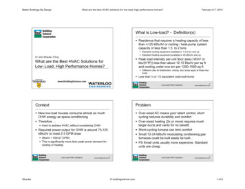
Normal Heat Exchanger TubesUsed heat exchangers on soft water; no signs of hard water scaling. No signs of copper turning black from heat stress Minimal signs of exterior corrosion. Blue-green color fromcondensation not a concern
Normal Heat Exchanger FinsUsed heat exchangers: Bottom view. Both are considered relativelyclean. Right photo has low levels of dust accumulated in the center. No signs of copper turning black from heat stress Dust on fins can cause performance and reliability problems, butwould not be a factor in causing leaks.
Hard Water ScalingTemperature of fins and pipesUnder normal conditions, fins and pipes arereachunacceptablelevelkeptin aansuitabletemperaturepoor quality waterscale buildupCaMg hard waterLeakageHeat
Water QualityHard Water DamageRecirculationSystem on HardWater
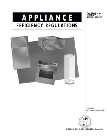
Bottom of Heat ExchangerUsed heat exchanger with signs of hard water scaling definitely evidentfrom scale formation of the tubes on the fins. Signs of copper turning black from heat damage in the left photo isprobably severe hard water scaling; on the right photo, it is probablymoderate hard water scaling.The black discoloring of the fins is severe. This black discoloring can beseen on the bottom and top of the heat exchanger (external).
Severe Scale Build Up (example)Used heat exchanger with severe signs of scale buildup Signs of copper turning black from heat damage. The amount ofscale buildup is evident. The black discoloring of the fins is severe. This black discoloring canbe seen on the bottom and top of the heat exchanger (external).
Product OverviewProduct Preservers Anti-Scale Filter is a better solution for tankless water heatersbecause it prevents scale buildup in the first place: The filter promotes formation of inactive scale crystals which flow through thewater heater without sticking to the heat exchanger. The filter does not add chemicals to the water or require electricity. It is virtually maintenance free, only requiring a simple filter change every twoyears.
Product SpecificationsConnection Size3/4”NPTMinimum Flow.5 gpmMaximum Flow10 gpmMinimum Pressure15 psiMaximum Pressure100 psiMinimum Temperature35 FInstall on cold water lines only
InstallationNote installation date for replacement element scheduling.
Cartridge e element at least once every years to ensure proper operation.Determine if equipment connected to your Product Preservers System must be turned off beforeshutting off water.If bypass line is installed, bypass system during filter change. Open bypass valve, close unit inletvalve, and close unit outlet valve. Figure AIf no bypass line is installed, turn off feed water.Release pressure to system by pressing red button on top of unit. Figure BUnscrew housing sump using included wrench if necessary. Figure CDiscard old cartridge. Retain spacer. Figure DInsert new cartridge into sump. Re-use the spacer that was included with the original unit. Figure DInspect O-ring for any damage and replace if necessary. Figure ERe-install filter housing sump. HAND TIGHTEN ONLY.Pressurize system by slightly opening feed valve. Once pressurized, open valve fully. Inspect sealsfor any leaks. If there is a leak, you may tighten the sump slightly more with the wrench.Flush system for 2 minutes with drain valve open. If no drain valve is installed, disconnect fromequipment for flush cycle.Turn on all equipment connected to system.Record filter change date for replacement element scheduling.
WarrantyLimited WarrantyCompany warrants its Product Preservers Anti-Scale Systemas follows: The Product Preservers cartridge system is warranted tobe free of defects in materials and workmanship for twoyears from the date of original shipment. Product Preservers filter cartridges are warranted forperformance for a period of two years from the date oforiginal installation when installed and operated inaccordance with the instructions in the correspondingInstallation and Operation Manual.
Severe Scale Build Up (example)Used heat exchanger with severe signs of scale buildup Signs of copper turning black from heat damage. The amount ofscale buildup is evident. The black discoloring of the fins is severe. This black discoloring canbe seen on the bottom and top of the heat exchanger (external).
Electrical Requirements
ElectricityElectrically grounded,but not to the wateror gas pipingAC 120V 60 Hz SupplyOn/Off switch orpigtailSurge protectorrecommendedBack-up power supplyis recommended inareas with frequentoutagesConnect power supply:120VAC 60HzGround
Make up Air / Quality
Make up AirMake-up air volume (Non-DV indoor installations) Air drawn from indoors – 1 in2 per 1,000 BTU/h Air drawn from outdoors – 1 in2 per 4,000 BTU/hWater heater sizeWhen drawing make-up airfrom outside the buildingMAX 199,000 BTU49.8 Sq. INWhen combustion air is suppliedfrom outside the building, anopening communicating directlywith the outside should have aminimum free area of onesquare inch per 4,000 BTUHinput of the total input rating ofwater heater in the enclosedarea.When drawing make-up airfrom inside the building (fromother rooms within)199 Sq. INWhen combustion air is suppliedfrom inside the building, anopening communicating with therest of the dwelling should havea minimum free area of onesquare inch per 1,000 BTUHinput of the total input rating ofwater heater in the enclosedarea. This opening should neverbe less than 199 sq. in.Example: Minimum recommended air supply opening size for the 510 model
Make-Up AirMake-up air quality (Non-DV indoor installations)If you will be installing the unit in acontaminated area with a high level of dust,sand, flour, aerosols or othercontaminants/chemicals, they can becomeairborne and enter and build up within the fanand burner causing damage to the unit. Inthose environments (e.g. residential orcommercial laundry facilities, hair salons, petsalons, chemical plants etc.), please purchase atankless model that is direct-vent convertible.Direct venting allows the water heater to drawfresh intake air from the outside.
Make-Up AirOther Ways to Vent a Two-Pipe SystemVertical Concentric TerminationSystemTwo penetrations through the wallor roofAA3ft.A3ft.3ft.Air supply inletExhaust terminationAir intakeExhausttermination(Always follow local codes)
Venting Options
Condensing Single Pipe
Condensing Two Pipe
Condensing Common Vent
Non-Condensing Stainless Venting
Non-Condensing Concentric Venting
BASIC SIZING
Product Selection Guide To select the right unit or multiple units for a home, three factors are ofcritical importance – Incoming ground water temperature Will determine the amount of “temperature rise” required toachieve the desired hot water outlet temperature– Set-point temperature Standard factory setting is 120 F or 122 F, but some applicationsmay require lower or higher temperature settings– Peak hot water demand How much hot water the home will need during its peak demand
Incoming Water Temperature
Install ExampleLuxury HomeMaster ShowerSystem(12 GPM)5 StandardShowers(12 GPM)2 Kitchens(6 GPM)Total PossibleDemand(30 GPM)OwnerEstimatedDemand(20 GPM)Hot/Cold MixRatio of 70/3070% of 20 GPM 14 GPM @122 FInstalled (2)910s(via Easy Link!) ProductionCapability in theMidwest: 16 GPM@ 122 F
Larger ApplicationsApplication designers/engineers can decide whether to size for full flow,expected flow, or utilize probability models such as the Hunter Curves.For large-scale applications such as hotels, apartment complexes, and largerestaurants, Hunter Curves are commonly used to estimate the peak flow ratedemand when given the total amount of fixture units within an application.It is up to the application designer/engineer to determine the amount of fixtureunits within any given application.We are always willing to assist when sizing large-scale applications. Pleasecontact Tankless Technical Support for assistance.
Hunters Curve
Tankless Applications Domestic Hot Water Systems:From an Apartment with a Single Shower, Washer, or Dishwasher to Luxury Homes with MultipleShowers, Spas, and Washers Radiant Floor Heating Systems: (Check Local Codes For “H” Stamp)This is fast becoming the preferred method of heating. Tankless is an excellent heat source! Laundromats, Health Clubs, Beauty Salons*, Etc:* Note: Beauty Salons must have direct vent or source of fresh air. Solar Hot Water Systems:With Tankless Back-up for Heating or DHW or Both!Our heaters work great with Solar! Restaurants and Hotels:We can custom size the installation to every need. Storage Tank Systems for Increased dump loads
Maintenance
Contaminant-freeIf the water heater is installed in acontaminated area with a highlevel of dust, lint, sand, grease,aerosols, or other contaminants,they can become airborne andenter into the air intake. Thecontaminants will build up withinthe fan and burner assemblycausing abnormal flame conditionsdue to lack of combustion air,damaging many components ofthe unit.In order to prevent the need forfrequent maintenance, it issuggested that the area around thewater heater is kept dust or debrisfree. In poor environments whereair quality cannot be improved, it issuggested that the water heater bedirect-vented (if the water heatermodel is convertible).
Flame/AFR sensorSensing elements (AFR& flame sensors)In dirty or dusty environments, the flamesensor can become coated up with blacksoot. This coating prevents electrical currentfrom the flame sensor to travel to ground.Connectionleads to thePCBFlameFine-grit sandpaper can be used to polish theflame/AFR sensor. The sensor must becleaned to a bright finish.rodAFRRod
Burner cleaningDirty flame/AFR sensors alsoindicate that the burner may betoo dirty. A dirty burner canpossibly cause a number ifdifferent error codes such as101, 111, 121, and 991.Many times, compressed air isnot enough. In these cases, useorange clean, simple green, orother safe degreasers. Take carenot to damage the burner gasketsduring the cleaning process.
Fan and combustion chamberWhile cleaning the burner, inspectthe combustion chamber and fanmotor. Dust may have built up onthese components as well. Cleanwith compressed air and a towel.
Heat exchanger replacementsIn the case of damaged orleaking heat exchangers,replacement will beneeded.It is important to be carefulduring the removal andreplacement process.Follow all steps carefully.Refer to Takagi’s heatexchanger replacementinstructional videos forassistance.
Draining and inlet filterOver time, the inletfilter may getclogged from debris.A dirty/clogged inletfilter can causenumerous issues e.g.loss of pressure,temperaturefluctuations, etc.To clean the filter,close all shut offvalves and drain thewater heater.Remove the filterand clean with asmall brush.If the water heaterwill not be in use fora long duration andis installed in afreezingenvironment, thewater heater mustbe properly drainedin order to avoidfreeze damage.
Descaling/FlushingHard water is a severe problem for thecopper coils inside the heat exchanger.Scale buildup tends to occur very readilyat high temperatures, sometimes causingthe heat exchanger to fail within a veryshort time. Heat exchanger failure dueto scale buildup from hard waterconditions is NOT covered by warranty.By the time flushing or descaling isperformed on a water heater,irreversible damage may have alreadybeen done to the heat exchanger.A water softener or effective form ofscale inhibitor should be installed onthe cold water line before the waterheater. Preventing scale buildup ishighly preferred overdescaling/flushing.
De-Scaling/FlushingIn cases where it is already too late toinform the customer about the benefitsof water softening or scale inhibitors,and flushing is needed, use only weakacid based solutions e.g. food-gradecitric acid, food-grade phosphorus acid,white vinegar etc.Use of our accessory isolationvalve kits are recommended foreasier maintenance.
Advantages
Roughly thesize of carryon luggageand the unitmounts highon a wall.:Before:IntroductionAfter:
Typical Energy Factor (EF) Range:DefinitionTank Type (40 to 75 gal.).53 to .64Tankless.81 to .95Energy Star 2012MinimumTank: 0.62Tankless: 0.82Savings Increase:32.3%32.3%Overall energy efficiencybased on the amount ofhot water produced perunit of fuel consumedover a typical day.Factors include:-Recovery Efficiency-Standby Losses-Cycling Losses
Typical Annual Operating Costs Range:Tank Type 1.00/therm 220 to 283 1.50/therm 330 to 424Tankless 1.00/therm 143 to 186 1.50/therm 214 to 279Savings30% to 50%Annually 120 to 210
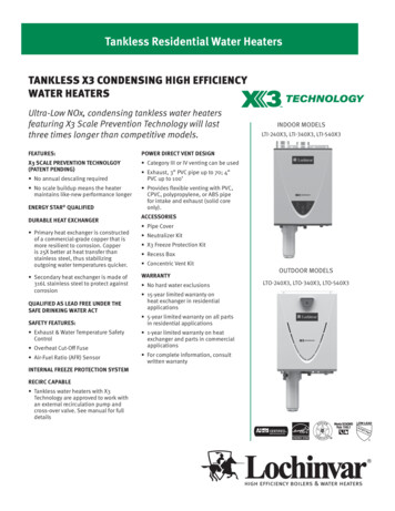
Temperature (F)Temperature Drop: Typical 50 gal. Tank-typePower Vent Model vs. T-K3(2 x 2.5 GPM showers at 105 F)160.0140.0120.0100.080.060.040.020.00.0PV50T-K30 5 10 15 20 25 30 35 40 45 50 55 60Time (minutes)
Zero GasUsageExamples:-Traveling for Work-VacationingEndless HotWaterExamples:-Long Relaxing Shower-Guests Visiting
Provides 3 functions within the water heater: flow adjustment, bypass, and two-way functions (540) . error, and unit will shut down Exhaust Thermistor Flat plate High Limit. Overheat Cutoff Fuse . Product Preservers Anti-Scale Filter is a better solution for tankless water heaters .