Transcription
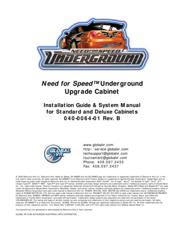
Need for Speed UndergroundUpgrade CabinetInstallation Guide & System Manualfor Standard and Deluxe Cabinets040-0064-01 Rev. pport@globalvr.comtournament@globalvr.comPhone: 408.597.3435Fax: 408.597.3437 2006 Electronic Arts Inc. Electronic Arts, Need for Speed, EA GAMES and the EA GAMES logo are trademarks or registered trademarks of Electronic Arts Inc. in theU.S. and/or other countries. All rights reserved. EA GAMES is an Electronic Arts brand. Dodge is a trademark of DaimlerChrysler Corporation. Dodge Neon and itstrade dress are used under license by Electronic Arts Inc. :DaimlerChrysler Corporation 2004. Honda , the 'H' logo , Acura , the stylized 'A' logo , Civic , Si ,Integra Type-R , S2000 , RSX , Type-R and Type-S names, emblems and body design elements are trademarks and/or intellectual property rights of Honda MotorCo., Ltd., used under license. Tiburon (Tuscani) is a registered trademark owned and licensed by Hyundai Motor Company. Mazda MX-5 Miata and Mazda RX-7 are usedunder the approval of Mazda Motor Corporation. Mitsubishi, Eclipse, and Lancer names, emblems and body designs are trademarks and/or intellectual property rights ofMitsubishi Motors Corporation and used under license to Electronic Arts Inc. NISSAN, SKYLINE, 350Z, SENTRA and 240SX are trademarks and/or intellectual propertyrights of NISSAN MOTOR CO.,LTD. And are used under license to Electronic Arts Inc. PEUGEOT 206 GTI S16 2003 is used under license from AUTOMOBILES PEUGEOTby Electronic Arts. SUBARU, IMPREZA and WRX names, emblems and body designs are properties of Fuji Heavy Industries Ltd. Toyota, Supra, and Celica aretrademarks of Toyota Motor Corporation, and used with permission. Trademarks, design patents and copyrights are used with the permission of the ownerVOLKSWAGEN AG. The names and logos of all after market car part companies are trademarks of their respective owners and are used by permission. All rightsreserved. EA GAMES is an Electronic Arts brand. GLOBAL VR and the GLOBAL VR logo are registered trademarks of Global VR, Inc. All other trademarks are theproperty of their respective owners. U.S. Patent Nos. 5,269,687; 5,354,202; and 5,577,913 used under license from Midway Games West IncTournaments are not sponsored or administered by Electronic Arts or their Licensors.GLOBAL VR IS AN AUTHORIZED ELECTRONIC ARTS DISTRIBUTOR.
Table of ContentsTable of ContentsPreface. 5Safety . 5Warnings. 6Environmental Conditions . 6FCC Notices (United States). 6Chapter 1 — Introduction. 7Need for Speed Underground Description. 7Need for Speed Underground Upgrade . 7Chapter 2 — Upgrading the Cabinet. 8Need for Speed Underground Upgrade KitContents . 8Primary Upgrade Steps. 9Tools Required. 9Standard Cabinet Hardware Upgrade . 101. Check Power Plate Wiring andGrounding. 102. Install the 6-Speed Shifter. 123. Install the NOS Buttons and SmartCardReader. 143.1 Install Left NOS Button . 143.2 Remove Monitor Bezel andCover Plates. 153.3 Install Right NOS Button . 163.4 Install SmartCard Reader . 163.5 Re-Install Bezel and RouteHarnesses. 16Deluxe Cabinet Hardware Upgrade. 181. Inspect the Cabinet . 182. Install the 6-Speed Shifter. 183. Install the NOS Buttons . 204. Install the SmartCard Reader . 22Install PCI USB Card and Make Connections(All Cabinets). 23Install the Lighting Kit . 24Install a Dollar Bill Validator (Optional) . 25Install the Cabinet Artwork . 25Standard Cabinet Artwork . 25Deluxe Cabinet Artwork . 27Install the Software. 29Test, Set Up, and Register your Cabinet. 30Linking Cabinets . 30Linking Cabinets Without Broadband . 31Linking Cabinets that use a BroadbandInternet Connection . 32Checking the Game Dongle . 33Connecting an External Monitor. 33Chapter 3 — Playing a Game. 34Starting the Game. 34Need for Speed Underground Upgrade System ManualPage 2 of 96Game Play.35Modes of Play.36Operator-Run Local Tournaments .36Chapter 4 — Setting Up Tournament Play.37Getting Started.37Cabinet Registration .37Navigating the Registration Screens.38Web Registration for Existing Operators.38Registration for Existing Operators withoutWeb Access.38Registration for New Operators.38Register With Your 4-Digit Registration Key.39Register with an Active Operator Card.42Manually Entering your Location .45Chapter 5 — Operator Menu and GameSetup .46Navigating Through the Game Operator MenuScreens .46Machine Information Menu .48Game and Coin Options Menu .49Reset Stats/Settings Screen .50Accounting Screens.51Current Location Income Screen .52Game Statistics Screens.52Play Control Test Screen .53Monitor Calibration Screen.54Sound Test.55System Test.56Link Status .57Registration Options.58Chapter 6 — System Recovery and GameInstall CDs.59Using the System Recovery CD .59Using the Game Install CDs.59Chapter 7 — Service and Repair .60Opening the Control Panel .60Force-Feedback Steering System Service.605 KΩ Steering Pot (Potentiometer)Replacement .61Force-Feedback Belt or Motor Replacement .62Force-Feedback PCB Replacement .63Driving Control Panel Button Service .63Pedal Assembly Service .645 KΩ Gas and Brake Pot (Potentiometer)Replacement .64Six-Speed Shifter and E-Brake Service .65Six-Speed Shifter Replacement .65Six-Speed Shifter Micro Switch Service.65040-0064-01 Rev. B 1/20/2006
Table of ContentsShifter Bottom Plate Replacement.65E-Brake Button Service .66Wells-Gardner Monitor Replacement .66Wells-Gardner Monitor Chassis PCBRemoval .67Audio Amp and Speakers Service.69Audio Amp PCB Replacement .70Front (Marquee) Speaker Replacement.70Center Speaker Replacement .70Rear (Seat) Speaker or SubwooferReplacement .70Computer Replacement .71Coin Mech Replacement .72Coin Meter Replacement.72Dollar Bill Validator Replacement .72SmartCard Reader Replacement .73SmartCard Dispenser Service .73SmartCard Dispenser Replacement .74Power Distribution Service .74AC Power Plate (Standard Cabinets).74AC Power Strip Replacement .75DC Power Supplies .75Cabinet Lighting Service.77Marquee Florescent Light Service.77Leader Light Service .77Brake Light Replacement.77Cold-Cathode Light Service.78Setting the Computer BIOS (CMOS) .78Chapter 8 — Troubleshooting.80Video Troubleshooting .80Audio Troubleshooting.81Control Troubleshooting .82Cabinet Linking Troubleshooting .83Miscellaneous Troubleshooting .84Connection Troubleshooting .85External Monitor Troubleshooting.86Chapter 9 — Replacement Parts.88Documents and Software .88Upgrade Kit Parts .88Existing Cabinet Parts .88Chapter 10 — Diagrams .90Warranty Service .95Warranty Information .95Technical Support.96List of FiguresFigure 1. Disconnect Power and RemovePower Plate . 10Figure 2. Power Plate Wiring (Inside Cabinet)11Figure 3. Coin Vault Ground Lug. 11Figure 4. Separating Seat from Cabinet. 12Figure 5. Shifter Harnessing Diagram(Simplified) . 12Figure 6. Lighted Button Connections. 14Figure 7. Opening the Control Panel . 15Figure 8. Removing the Bezel . 15Figure 9. SmartCard Reader and NOS ButtonLocations (Standard Cabinet). 16Figure 10. SmartCard Reader Assembly . 16Figure 11. NOS Button Connections Diagram . 17Figure 12. NOS Button Harness Connectors . 17Figure 13. Separating Seat from Cabinet. 18Figure 14. Shifter Harnessing Diagram(Simplified) . 18Figure 15. Lighted Button Connections. 20Figure 16. NOS Button and SmartCard ReaderLocation (Deluxe Cabinet) . 21Figure 17. NOS Button and SmartCard ReaderInstallation (Deluxe Cabinet) . 21Figure 18. NOS Button Connections Diagram . 22Figure 19. NOS Button Harness Connectors . 22040-0064-01 Rev. B 1/20/2006Figure 20. Installing the Light Kit.24Figure 21. Cold-Cathode Light Wiring .24Figure 22. Dollar Bill Validator DIP SwitchSettings .25Figure 23. Installing the Marquee Artwork(Standard Cabinet).26Figure 24. Graphics Placement (StandardCabinet) .27Figure 25. Installing the Marquee Artwork(Deluxe Cabinet).28Figure 26. Graphics Placement (DeluxeCabinet) .28Figure 27. Linking Cabinets WithoutBroadband.31Figure 28. Checking Link Status.31Figure 29. Linking Cabinets with Broadband .32Figure 30. Parallel and USB Game Dongles.33Figure 31. Selecting Track and Car Options .34Figure 32. Driving Screen Functions .35Figure 33. Registration Process Flowchart .37Figure 34. Setting Cabinet Volume.46Figure 35. Game Operator Menu Flowchart .47Figure 36. Machine Information Screen .48Figure 37. Game and Coin Options Screen.49Figure 38. Reset Stats/Settings Menu .50 2006 GLOBAL VR, INC.Page 3 of 96
Table of ContentsFigure 39. Accounting Info Screens.51Figure 40. Current Location Income Screen .52Figure 41. Game Stats Menu Screens .52Figure 42. Play Control Test Screen .53Figure 43. Monitor Calibration Test Screen.54Figure 44. Monitor Remote Control Board .54Figure 45. Sound Test Screen .55Figure 46. System Test Screen .56Figure 47. Cabinet Link Status Screen .57Figure 48. Registration Options Screen .58Figure 49. Opening the Control Panel.60Figure 50. Force-Feedback Steering SystemHarnessing Diagram .61Figure 51. Replacing the 5 KΩ Steering Pot .62Figure 52. Servicing the Steering Motor .62Figure 53. Replacing Button Lamps.63Figure 54. Pedal Assembly Details .64Figure 55. Shifter Pattern and Micro SwitchActuation .65Figure 56. Cable Connections to the MonitorChassis .66Figure 57. Monitor Mounting Nut Locations .67Figure 58. Removing the Monitor PCBMounting Hardware.68Figure 59. Disconnecting the Chassis NeckPCB and Second Anode Lead.68Figure 60. Monitor PCB Cables .69Figure 61. Audio Amp Connections, VolumeAdjustment, and Speaker Location.69Figure 62. Unbolting the Computer .71Need for Speed Underground Upgrade System ManualPage 4 of 96Figure 63. Servicing the Coin Mech and CoinMeter . 72Figure 64. Dollar Bill Validator DIP SwitchSettings. 73Figure 65. Filling the SmartCard Dispenser . 74Figure 66. AC Power Plate Connections . 75Figure 67. AC Power Plate . 75Figure 68. 24 VDC Power SupplyConnections. 76Figure 69. External PC Power SupplyConnections. 76Figure 70. Accessing the Marquee Light,Leader Light, and Speakers. 77Figure 71. Selecting the Settings Tab in theDisplay Control Panel . 86Figure 72. Selecting the Video Card NameTab . 86Figure 73. Choosing a Display Pair withCloning. 87Figure 74. Confirming Display Settings . 87Figure 75. Seat Assembly Parts . 89Figure 76. Simplified Wiring Diagram. 90Figure 77. Detailed Wiring Diagram . 91Figure 78. Computer Rear Panel Connections. 92Figure 79. Setting up a Dial-up GameNetwork. 93Figure 80. Setting up a Broadband GameNetwork. 94040-0064-01 Rev. B 1/20/2006
PrefacePrefaceSafetyPlease read this page before preparing your arcade cabinet for game play.The following safety instructions apply to all game operators and service personnel. Specific warnings and cautions willbe included throughout this manual.Use the following safety guidelines to help protect the system from potential damage and to ensure your personal safety: Make sure that the switch on the back of the computer is set to match the AC power in use at your location: 115 volts / 60Hz in most of North and South America and some Far Eastern countries such as Japan, SouthKorea and Taiwan 230 volts / 50Hz in most of Europe, the Middle East and the Far East To help prevent electric shock, plug the system into a properly grounded power source. These cables are equippedwith 3-prong plugs to help ensure proper grounding. Do not use adapter plugs or remove the grounding prong froma cable. If you must use an extension cable, use a 3-wire cable with properly grounded plugs. To help protect your system from sudden increases and decreases in electrical power, use a surge suppressor, lineconditioner or Uninterruptible Power Supply (UPS). Be sure nothing rests on the system's cables and that the cables are not located where they can be stepped on ortripped over. Keep your system far away from radiators and other heat sources. Do not block cooling vents.Precautions for Game Operation The avoid injury and accidents, people who fall under the following categories should not play the game: Those who need assistance when walking. Those who have high blood pressure or a heart problem. Those who have experienced muscle convulsions or loss of consciousness when playing a video game or similaractivities. Those who have trouble in the neck or spinal cord. Intoxicated persons. Pregnant women. Persons susceptible to motion sickness. Persons who do not abide by the warning labels on the game. A player who has never been adversely affected by light stimulus might experience dizziness or headache whenplaying the game. Small children can be especially susceptible to these conditions. Caution guardians of smallchildren to keep watch over their children during play. Instruct those who feel sick during play to see a doctor. To avoid injury from falling objects, and electric shock due to spilled drinks, instruct players not to place heavyitems, food, or drinks on the product. To avoid electric shock or short circuit, do not allow customers to put hands and fingers or extraneous matter in theopenings of the product. To avoid risk of injury from falling, immediately stop customers from leaning against or climbing on the product.040-0064-01 Rev. B 1/20/2006 2006 GLOBAL VR, INC.Page 5 of 96
PrefaceWarningsTo avoid electrical shock, unplug the cabinet before performing installationor service procedures.GLOBAL VR assumes no liability for any damages or injuries incurred whilesetting up or servicing the cabinet. Only qualified service personnel shouldperform installation or service procedures!Environmental ConditionsCabinet is intended for indoor use only. Be sure to keep the cabinet dry and maintain operating temperatures of 10 40 C (50 -104 F).FCC Notices (United States)Electromagnetic Interference (EMI) is any signal or emission radiated in free space or conducted along power or signalleads, that endangers the functioning of radio navigation or other safety service, or that seriously degrades, obstructs, orrepeatedly interrupts a licensed radio communications service. Radio communications services include, but are notlimited to, AM/FM commercial broadcast, television, cellular services, radar, air-traffic control, pager, and PersonalCommunication Services (PCS). These licensed services, along with unintentional radiators such as digital devices(including computer systems) contribute to the electromagnetic environment.Electromagnetic Compatibility (EMC) is the ability of items of electronic equipment to function properly together in theelectronic environment. While this computer system has been designed and determined to be compliant with regulatoryagency limits for EMI, there is no guarantee that interference will not occur in a particular installation. If this equipmentdoes cause interference with radio communications services, which can be determined by turning the equipment off andon, you are encouraged to try to correct the interference by one or more of the following measures: Re-orient the receiving antenna. Relocate the cabinet relative to the receiver. Plug the game into a different outlet so that the computer and the receiver are on different branch circuits.If necessary, consult a Regulatory EMC representative of GLOBAL VR or an experienced radio/television technicianfor additional suggestions. You may find the FCC Interference Handbook, to be helpful. It is available from the U.S.Government Print Office, Washington, DC 20402.This device has been tested and complies with the limits for a Class A digital device pursuant to Part 15 of the FCCRules. These limits are designed to provide reasonable protection against harmful interference when the equipment isoperated in a commercial environment. This equipment generates, uses, and can radiate radio frequency energy. If notinstalled and used in accordance with the instruction manual, it may cause harmful interference with radiocommunications. Operation of this equipment in a residential area is likely to cause harmful interference, in which caseyou will be required to correct the interference at your own expense.Operation is subject to the following conditions: This device may not cause harmful interference. This device must accept any interference received, including interference that may cause undesired operation.Need for Speed Underground Upgrade System ManualPage 6 of 96040-0064-01 Rev. B 1/20/2006
Chapter 1 — IntroductionChapter 1 — IntroductionNeed for Speed Underground DescriptionBuild and race the ultimate urban exotic with Need for Speed Underground.Take control of top import street tuners like Toyota Celica, Nissan 350Z, Mitsubishi Eclipse andthe exclusive Nissan Skyline GT-R. Play Career and customize your car with licensedaftermarket parts to build your own unique ride.Force-feedback steering, surround sound and a 6-speed shifter make Need for Speed Underground a truly engaging driving experience.Own the Streets Linkable – allowing up to 4 players to compete in blistering head-to-head competition. Tournament Play – with National Tournaments and Wednesday Tournament eventsthroughout the US. Career Mode – allows players to choose their car and compete in a series of 81 races, earningcustom performance parts and upgrades along the way. Players can store 4 Careers on onePlayers’ Card! GLOBAL VR Players’ Card Compatible – thousands of registered players are ready todrive, and new players can purchase a SmartCard format Players’ Card to store their data.Need for Speed Underground UpgradeThe Need for Speed Underground Upgrade Kit is available for existing Need for Speed cabinets. The upgrade kit includes the new Need for Speed Underground software, 6-speedshifter, Players’ Card reader (for Tournament and Career Mode play), NOS button, and newartwork.040-0064-01 Rev. B 1/20/2006 2006 GLOBAL VR, INC.Page 7 of 96
Chapter 2 — Upgrading the CabinetChapter 2 — Upgrading the CabinetNeed for Speed Underground Upgrade Kit ContentsThe Need for Speed Underground Upgrade Kit contains the items listed below. For a detailedparts list, refer to Chapter 9 — Replacement Parts on page 85.Software, Documents, and Artwork:DescriptionPart #System Recovery Disk050-0070-01Game Install Disks (2)050-0071-01Installation Guide & System Manual (This Document)040-0064-01Software Restore Guide040-0069-01Serial Number LabelL-0069Cabinet Artwork (For details, see page 26 for Standard cabinets with 27" monitors,or page 27 for Deluxe cabinets with 39" monitors.)Hardware:RefDescriptionPart #16-Speed ShifterAssembly45037-002Shifter Harness115-0060-013Shifter Harness115-0061-014Four-Port PCI USB Card083245Game DongleUSB-KQRTG6NOS Button Cover andGraphic59-6010-12 &HP142201-19987NOS Button Assemblyand Back Plate45044-00 (Std)45043-00 (Dlx)8SmartCard ReaderAssembly45038-00 (Std)45039-00 (Dlx)Telephone Cable (notshown)TDC207Light Kit Assembly(not shown)45042-00Note: Standard Cabinet (27" monitor) hardware pictured.Options:A Dollar Bill Validator may be installed as an option.A SmartCard dispenser is available as a separate kit.Need for Speed Underground Upgrade System ManualPage 8 of 96040-0064-01 Rev. B 1/20/2006
Chapter 2 — Upgrading the CabinetPrimary Upgrade StepsNote: Standard cabinets have 27" monitors; Deluxe cabinets have 39" monitors.1Inspect CabinetCheck Ground WiresStandard: Page 10Deluxe: 182Install 6-Speed ShifterStandard: Page 12Deluxe: Page 183Install NOS ButtonsStandard: Page 14Deluxe: Page 204Install SmartCard ReaderStandard: Page 16Deluxe: Page 225Install Four-Port PCI USB Cardand Make ConnectionsPage 236Install Lighting KitPage 247Install Dollar Bill Validator (Optional)Page 258/9InstallArtwork10Standard:Page 26Deluxe:Page 27You can do thesesteps together.InstallSoftwareTest, Set Up, and Register your CabinetPage 26Page 30Tools Required Screwdriver with assorted Torx Security bits (including T-15 and T-27) and Phillips bits Nut drivers Exacto knife Drill and 3/4" bit (for lighting kit installation) Stepladder (optional)040-0064-01 Rev. B 1/20/2006 2006 GLOBAL VR, INC.Page 9 of 96
Chapter 2 — Upgrading the CabinetStandard Cabinet Hardware Upgrade1. Check Power Plate Wiring and GroundingYour cabinet must be properly wired and grounded to ensure safety and proper operation. Beforeinstalling the new equipment, check the wiring as described in this section.The steps in this section apply only to Standard cabinets. Deluxe cabinets (39"monitors) have adifferent type of power plate.WARNING: ELECTRIC SHOCK HAZARD. Disconnect the cabinet power cord beforeperforming the steps in this section.1. Disconnect the power cord from the cabinet.2. Remove the four (4) power plate mounting nuts and bolts and remove the power plate.3. If a grounding wire is connected to any of the power plate mounting bolts, connect that wireto the ground lug on the EMI filter, as described in the next part of this document. The powerplate mounting bolts do not provide an adequate ground.Figure 1. Disconnect Power and Remove Power Plate4. Refer to Figure 2 and inspect the power plate to make sure that the correct color wire isconnected to each connector.Need for Speed Underground Upgrade System ManualPage 10 of 96040-0064-01 Rev. B 1/20/2006
Chapter 2 — Upgrading the CabinetFigure 2. Power Plate Wiring (Inside Cabinet)5. Confirm that a ground wire is connected from the ground lug on the EMI filter to the groundlug on the coin vault. Make sure this wire is tightly connected.6. If there is no ground wire from the ground lug on the EMI filter to the ground lug on the coinvault, do the following:a. Install a 2 1/2' ground wire to the lug on the right of the EMI filter, as shown in Figure 2.Use a #8-32 Kep nut to secure it in place. Secure the nut tightly.b. Use a #8-32 Kep nut to secure the other end of the ground wire to the coin vault ground lug,on top of the other ground wires, as shown below. Secure the nut tightly.Figure 3. Coin Vault Ground Lug7. This is a good time to make sure that the Ethernet and phone cables are connected from thecomputer to the appropriate ports on the inside of the power plate. A phone cable is providedin the upgrade kit in case one was not previously installed. Refer to Figure 78 on page 92 forcomputer connections.8. Re-install the power plate in the cabinet and secure it with the mounting nuts and boltsremoved in step 2. (Do not connect ground wires to the mounting bolts.)040-0064-01 Rev. B 1/20/2006 2006 GLOBAL VR, INC.Page 11 of 96
Chapter 2 — Upgrading the Cabinet2. Install the 6-Speed Shifter1. Turn off the cabinet and disconnect the power cord.2. Remove the four (4) Torx bolts from each side of the seat, as shown below, and slide the seataway from the cabinet so that you will be able to reach the harnesses.Figure 4. Separating Seat from Cabinet3. Refer to the figure below to make the shifter harness connections described in the steps thatfollow.CabinetExisting HarnessPart #: 115-0009-018-PinConnectorNew HarnessPart #:115-0060-01SeatNew HarnessPart #: 115-0061-01Power in from DC Power HarnessTo 6-Speed ShifterTo E-Brake ButtonExtra DC Power ConnectorExisting HarnessPart #: 115-0002-01Existing HarnessTo Brake LightsFigure 5. Shifter Harnessing Diagram (Simplified)Need for Speed Underground Upgrade System ManualPage 12 of 96040-0064-01 Rev. B 1/20/2006
Chapter 2 — Upgrading the Cabinet4. In the back of the cabinet, locate the unused 8-pin female connector on existing harness part #115-0009-01. It may be bundled with other harnesses on the cabinet wall to your left. It alsomay be labeled "KEYPAD" as shown in the figure below.5. Connect the 8-pin connector to the corresponding connector on harness part #: 115-0060-01 fromthe kit. Make sure that the white & yellow striped wires on the two connectors are aligned.6. Connect the 4-pin male DC power connector on the new harness (115-0060-01) to a DC powerconnector in the cabinet. If there is no unused DC connector, disconnect another device andconnect it to the Spare DC connector on the new harness.7. Route the 5-pin connector of the new harness (115-0060-01) through the hole in the bottom ofthe cabinet, near the back of the pedal assembly, so that you will be able to pull the harnessthrough to the seat assembly. (It is helpful to have a second person spot the harness and pull itthrough.)8. At the seat assembly, remove the three (3) Torx bolts from the top plate of the shifter and lift theshifter assembly out of its housing.9. Disco
Mitsubishi Motors Corporation and used under license to Electronic Arts Inc. NISSAN, SKYLINE, 350Z, SENTRA and 240SX are trademarks and/or intellectual property rights of NISSAN MOTOR CO.,LTD. And are used under license to Electronic Arts Inc. PEUGEOT 206 GTI S16 2003 is used under license from AUTOMOBILES PEUGEOT by Electronic Arts.