Transcription
PDHonline Course M134 (3 PDH)Practical Considerations in PumpSuction ArrangementsInstructor: Randall W. Whitesides, PE2012PDH Online PDH Center5272 Meadow Estates DriveFairfax, VA 22030-6658Phone & Fax: 703-988-0088www.PDHonline.orgwww.PDHcenter.comAn Approved Continuing Education Provider
www.PDHcenter.comPDH Course M134www.PDHonline.orgPractical Considerations in Pump Suction ArrangementsCopyright 2003, 2008Randall W. Whitesides, P.E.Course OverviewAn important aspect of pump hydraulic system design is the suction or inlet conditions. Disregard forproper allowances can result in vortices, cavitation, and loss of prime. Pumps do not force liquidsthrough inlet or suction piping, but rather create lowered pressures at the suction nozzle which in turn induces the fluid to enter. Any design that impedes or lessens the efficient transport of this liquid will, ofcourse, result in less liquid being handled. Any design that encourages the introduction of entrained gasor liquid voids will likewise result in a less efficient pumping operation. In addition to poor performance,truly bad designs can in some cases actually result in physical damage to the pump or its parts.The study of pump suction system configuration can be broken down into two parts: (1) suction pipingand (2) suction source. Critical consideration must be given to both in order to properly design an efficient system. Proper suction piping design and installation considerations consist of pipe and pipe fittingsand their relationship, quantity, and relative location to the pump suction nozzle. Suction source designfactors include the geometry of the source and the relative location of the suction entrance point(s) to suction liquid surface, source enclosure boundaries, and other suction entrance points. This course deals withboth parts and is applicable generally to all types of pumps, since every pump’s successful operation anduseful life can be so dependent on a properly designed and thought-out suction arrangement.Course IntroductionThere are many factors that affect the operation of a pump. Important factors are total head, speed, liquidproperties, and physical arrangement/system connection. Included in the category of arrangement andconnection are the suction conditions. Excessive suction lift, shallow inlet submergence, or insufficientNet Positive Suction Head available (NPSHA), all spell serious trouble from vibration, cavitation, loweredcapacity, and reduced efficiency. While the Engineer may not have large control over some of the inherent process factors, with planning and foresight many times the pump suction conditions can be optimizedin the design stage. This course offers ideas and summarizes generally accepted guidelines of practicalconsideration in pump suction arrangements.Practical Considerations in Pump Suction Arrangements 2003, 2008 Randall W. Whitesides, CPE, PE1
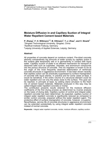
www.PDHcenter.comPDH Course M134www.PDHonline.orgCourse ContentDo Pumps Suck?True of False? There appears to be a continual disagreement on this subject. Actually, some puristswould contend that a true state of absolute suction is impossible (except in the perfect vacuum of space)and that only varying degrees of flow-causing differential pressure exist. Rightly or wrongly, the termsuction is firmly planted in hydrology as is evidenced with its extensive use as an adjective in pump terminology, i.e., suction connection, suction line, suction lift, etc. Pumps create a partial vacuum lettingatmospheric (or positive source) pressure force liquid into a lower pressure area of the pump; this is thedefinition of suck. What is important to know is the fact that any impedance to hydraulically balanced,unrestricted flow, induced by this “suction”, will be problematic.In Order to Form a More Perfect StabilityThe single most important function of a pump suction system is to supply an unencumbered, evenly distributed flow to the pump. This is true regardless if the intake configuration is a single pipe, an opensump, or a river. Secondly, the pump suction system should not promote the external introduction, or internal creation, of compressible flow elements, i.e., air, vapor, or gas.Improper design of the suction piping or sump, or inadequate pipe support exterior to the pump, can causehydraulic disturbances that manifest in chronic and eventual destructive random frequency vibrations.Interestingly enough, internal pump problems such as bearing failures, seal failures, excessive erosion,excessive corrosion, excessive noise, and excessive vibration can many times be rooted to sources outsidethe pump itself and in the connected piping. Often times the trouble emanates from poor suction conditions and piping practices that encourage unbalanced hydraulic flow.Promoting hydraulic stability is maintaining hydraulic balance on pump rotating elements. If at all possible, the direct connection of any type of pipe fitting to the pump suction nozzle should be avoided. Pipefittings cause uneven flow patterns. In single end suction pump types, unbalanced flow axial to the pumpshaft causes unequal liquid introduction to the impeller eye. This results in unbalanced thrust which increases bearing wear, reduced bearing life, and premature seal failure. Direct connection of elbowsshould always be avoided. In double suction pumps, if directly connected elbows can not be avoided,they should be installed such that the elbows are in a plane perpendicular to the pump shaft. Figure 1 onthe following page is an illustration of a single end-suction centrifugal pump piping arrangement typically witnessed in industry, with fittings installed in close proximity to the suction nozzle.Practical Considerations in Pump Suction Arrangements 2003, 2008 Randall W. Whitesides, CPE, PE2
www.PDHcenter.comPDH Course M134www.PDHonline.orgFigure 1 – Typical single end-suction piping arrangementBeyond what would logically be surmised to be unbalanced flow attributable to the elbow, studies have determined that a secondary, rotating flow,is imparted in the fluid by elbows. This secondary rotating flow issuperimposed and conveyed with the main momentum flow in the axialdirection. In addition to an axial force in the x direction, ancillary forces areimparted to the surroundings in the y and z directions. This secondary flow,sometimes referred to as pre-rotational flow, is ultimately carried into theimpeller imparting additional damaging turbulence and inefficient internalrecirculation. Bottom line: Directly connected or closely placed elbows are detrimental to pump operation because of multiple and compounding reasons.The Ninety degree (90E) elbow is commercially produced in two styles: shortradius and long radius. The short radius elbow’s center line radius (A) is equalto the nominal pipe diameter (D). In the long radius elbow, A is equal to 1.5D.Obviously, the long radius 90Eelbow is more “sweeping” and imparts less turbulence and unbalanced flow than that of the short radius; it should be usedwhenever suction elbows are unavoidable.Practical Considerations in Pump Suction Arrangements 2003, 2008 Randall W. Whitesides, CPE, PE3
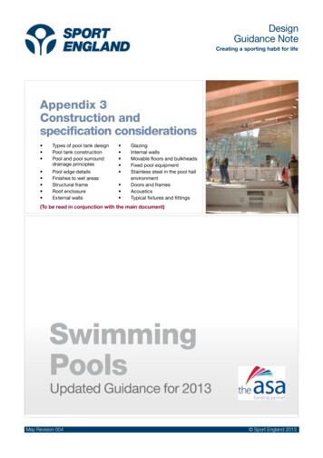
www.PDHcenter.comPDH Course M134www.PDHonline.orgFollowing the Straight and NarrowThe ideal suction pipe approach to the pump’s impeller eye is straight pipe. Field experience has shownthat the ideal minimum length of full-size straight pipe, devoid of any obstructions to flow, immediatelyupstream of the pump suction connection, should be 10D. The absolute minimum length of full-sizestraight pipe, devoid of any obstructions to flow, immediately upstream of the pump suction connection,should be 5D. This is illustrated in Figure 2.Figure 2 – The rule of 10DTaking It Smooth and EasyPump inlet piping should be designed and installed to provide smooth and orderly flow to the pump.The pump suction bell reduces the contraction entrance frictionallosses by “smoothing” the flow by elimination of a sharp inlet edge.Entrance fluid frictional losses can be reduced by as much as 80%depending on the size of the rounding. The suction bell also reducesthe approaching mean fluid velocity; it has been shown thatminimum submergence depth varies directly with fluid velocity as itrelates to vortex formation. (More on vorticies in a moment).Liquids undergoing sudden or sharp changes in cross-sectional flowarea have intensified differential pressure losses which reduce flow.Practical Considerations in Pump Suction Arrangements 2003, 2008 Randall W. Whitesides, CPE, PE4
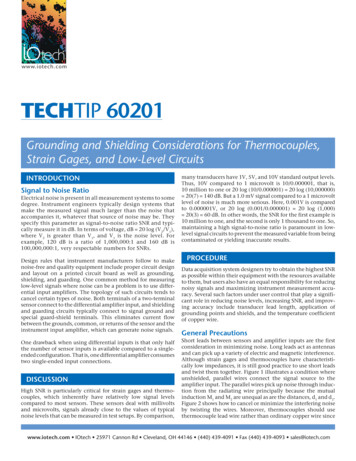
www.PDHcenter.comPDH Course M134www.PDHonline.orgSome Restrictions May Apply-Void Where ProhibitedCheck valves are installed on pump discharge lines to prevent liquid flow reversal with the succession ofpumping. In a similar fashion, a foot valve is simply a form of check valve, usually in a vertical position,usually incorporating a strainer, installed in the pump suction line (see Figure 3). The purpose of the footvalve is to preclude back-flow from the pump through the suction line. They are used to promote a liquidfilled suction line that hopefully will allow the pump to maintain prime. Much like standard check valves,they are available in various styles and principles of operation. By necessity they create an obstruction toflow and, therefore, should not be employed unless is deemed absolutely necessary.Figure 3 – Foot valve and suction strainerThe connection of a suction line to a larger pipe should be given special consideration. See Figure 4 forthe wrong and correct means of accomplishing this intersection. The correct method promotes streamlineflow and reduces the fluid frictional contraction loss. A separate and dedicated suction line should beused in situations where multiple pumps are taking suction from a common header, i.e., a manifold arrangement. Figure 5 shows a plan view of the wrong and correct manner to make header connections.Note that the minimum distance between connections should be 3D and that “y-branches” oriented in thedirection of flow should be used in lieu of a right angle or “tee” configuration. Figure 4 (the elevationview) again comes in to play in this situation to indicate the wrong and correct way to accommodate asize reduction from the header to the suction take-off line.Practical Considerations in Pump Suction Arrangements 2003, 2008 Randall W. Whitesides, CPE, PE5
www.PDHcenter.comPDH Course M134www.PDHonline.orgFigure 4 – Size reduction pipe intersectionFigure 5 – Plan view of pipe manifold arrangementFigure 6 is a plan view of a horizontal split case pump with several suction arrangement poor practices.They are: (1) A short-radius 90º elbow in the horizontal plane; (2) followed by a sudden contraction toaccommodate the pump’s nozzle size; (3) both located less than 5D from the suction nozzle. In contrast,Figure 7 illustrates an elevation (side) view of a double suction pump with two maybe not perfect, butnevertheless better, practices. They are: (1) A long-radius sweeping 90º elbow in the vertical plane, and(2) an eccentric reducer oriented with the flat at the top. (More on reducers and their implications momentarily).Practical Considerations in Pump Suction Arrangements 2003, 2008 Randall W. Whitesides, CPE, PE6
www.PDHcenter.comPDH Course M134www.PDHonline.orgFigure 6 – Plan view of horizontal split case pump suctionFigure 7 – Side view of horizontal split case pump suctionPractical Considerations in Pump Suction Arrangements 2003, 2008 Randall W. Whitesides, CPE, PE7
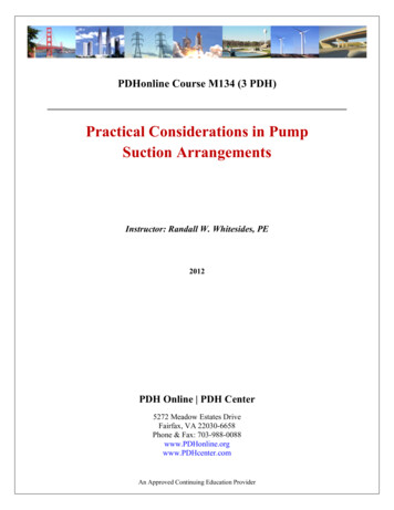
www.PDHcenter.comPDH Course M134www.PDHonline.orgConfusion on DiffusionControversial opinions can be found on the subject which has become known as suction diffusion. Actually, diffusion means to disperse or spread out. A suction diffuser is a special pipe fitting, sometimes inthe configuration of a tee or sharp elbow, which is installed directly on the pump’s suction connectionwhich contains, depending on the make, various configurations of flow straightening elements. Oftenthese special fittings may also incorporate some type of straining feature. Figure 8 shows a cut-awayview of a typical diffuser attached directly to a pump suction. Manufacturers of suction diffusers state that theycan be utilized to smooth, balance, and otherwise streamline liquid flow to the impeller eye when physical space isnot available to accommodate the recommended 5D to 10D full-size straight pipe provision.Figure 8 – Suction diffuserThe attribute of spatial compensation is somewhat debatable. A comparative examination of a number ofcommercially available diffuser models indicated that the average physical take-out, or length, plus therequired space for the removal of the screen, was equivalent to 5D. This is identical to the recommendedabsolute minimum of 5D normally sought. Even assuming that the diffuser has a space accommodatingfeature and that its use may produce the desired result, it introduces additional frictional resistance whichmay be problematic with limited NPSHA. If a straining element is present in the diffuser, then routine observation and maintenance will always be in order. Suction diffusers with straining elements should betreated with the same careful consideration, that will be discussed shortly, given a suction strainer whendeciding to install this type of device on the pump suction. With respect to diffusers, use them only whenPractical Considerations in Pump Suction Arrangements 2003, 2008 Randall W. Whitesides, CPE, PE8
www.PDHcenter.comPDH Course M134www.PDHonline.orgthe recommended minimum full-size straight pipe lengths can not be provided immediately upstream ofthe pump inlet port and certainly only after complete evaluation of the resultant flow characteristics.A Suction Source by Any Other NameTheoretically, any suction system arrangement can be considered a pump intake structure. However, theterm pump intake structure generally refers to a man-made, completely or partially enclosed or otherwiseflow capturing contri
www.PDHcenter.com PDH Course M134 www.PDHonline.org Practical Considerations in Pump Suction ArrangementsFile Size: 626KBPage Count: 24