Transcription
Keypad/Bluetooth/GSM Based Digital Door Lock SecuritySystemS. Umbarkar, G. Rajput, S. Halder, P. Harname and S. MendgudleDepartment of Electronics Engineering, RAIT, Nerul, Navi-Mumbai: 400706{ sachin.umb@gmail.com ; gyrajput@gmail.com }Abstract. This paper discusses the design and implementations of an electronic door lock/unlock compact system using the arduino platform. These security systems enable to lock/unlock the door using three differentmodes i.e. Keypad, Bluetooth and Global System for Mobile (GSM) modules. These three modules operate on a4-digit password. We can open or close the door by using keypad, bluetooth application from smart phone andalso by using 4 digit message from GSM phone. If any unknown person does the three consecutive unsuccessfulattempts to enter the password in any one of the system, then arduino controller will send a warning message topreset owner GSM mobile number and also initiate the buzzer alarm as a warning of unauthorized intrusion. Wehave got the good experimental results and promising analysis in all these three modules.Keywords: Arduino, Servo motor, 16x2 LCD display, Keypad, Bluetooth, GSM module.1 IntroductionIn 2011 the study report by National Crime Records Bureau (NCRB) [1], 58862 burglary cases was registered inIndia. According to the study by Alarm Industry Research and Educational Foundation (AIREF) [7], thiefspends less than 60 seconds for breaking the normal door lock. The report of “Home Safety Fast Facts” conducted by the Electronic Security Association’s (ESA) [6] concludes that 9 out of 10 burglars avoid homeswhich are having door alarm security system. These facts have encouraged the development of numerous security systems for both residential and commercial applications.Today it is essential to provide the security system employing various sensors and alarm system in residentialcommunities. Mallory Jone [5] implemented a security alarm system that has a number of sensors for smoke,fire, intrusion and application operation. A central monitoring system was provided for continues indication ofsensors. Transmitters were connected with sensors and receivers were connected with monitoring system for effective communication. The central monitor then display the indication with respect to each transmitter connected with particular sensor. Pratiksha [3], described a home security system with the GSM/GPRD technologyservices to achieve controlling of door lock by short message service (SMS). Also Adnan Ibrahim discussed thedesign and development of PIC supported security system with the GSM system for sending the alert messageon mobile for continues three unsuccessful attempts of password [2]. Another system was proposed by Ushie[4], in which door can be remotely controlled by a GSM phone set like a transmitter and another GSM phone setwith a dual tone multi frequency (DTMF) connected to the door motor with DTMF decoder interfaced with microcontroller chip.At present time door security is the most important and so we designed and implemented a digital door lock system which works in three different modules. From the keypad module we can directly enter the 4 digit passwordto lock and unlock the door. In bluetooth module, first we establish connection between our smart phone anddoor lock system bluetooth kit, then enter the password to lock/unlock door. Bluetooth module range is approximately 10 meters. GSM module is the most secured mode in which the owner has to enter the passwordthrough his mobile via text message to open or close the lock. The main advantage of GSM module is that it enables user to lock/unlock the door from remote location. The main advanced feature in all three modules is thatif unknown person enters three consecutive wrong passwords, it will send an alert message on GSM mobilenumber of the owner which is stored in arduino program and also start the buzzer alarm for security alert of thesociety.B. Iyer, S. Nalbalwar and R. Pawade (Eds.)ICCASP/ICMMD-2016. Advances in Intelligent Systems Research.Vol. 137, Pp. 749-757. 2017- The authors. Published by Atlantis PressThis is an open access article under the CC BY-NC license (http://creativecommons.org/licens)es/by-nc/4).
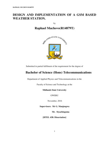
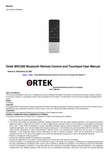
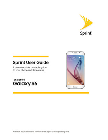
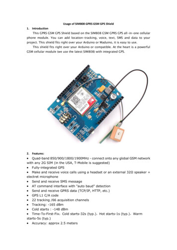
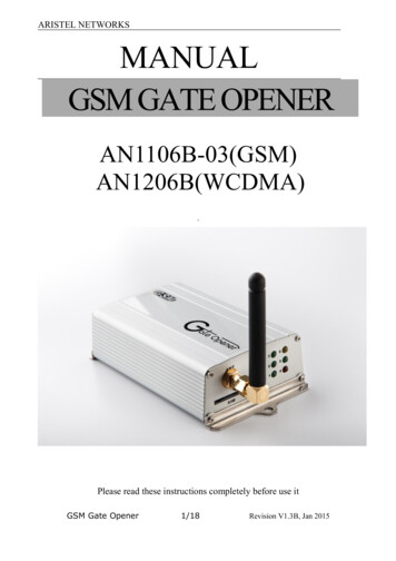
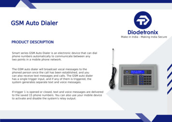
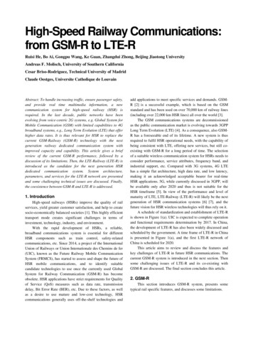
750Umberkar et.al.Key pad moduleBluetoothModuleLCD DisplayLED’sTmega2560Arduino MegaServo MotorGSM ModuleBuzzerFig.1. Block Diagram2 Components2.1 KeypadWe used a 4x4 keypad which has four columns and four rows which are connected to Arduino board. The password will be passed from keypad to the Arduino and Arduino will respond accordingly.Fig. 2. Keypad2.2 Bluetooth Module HC-05Bluetooth module is used for wireless transmission. Its range is 10 meters. This module is based on Cambridgesilicon radio BC417 2.4Ghz bluetooth chip. It is a complex chip which uses an external 8 bit flash memory. It isa small module which works on very less power that is 3.3V. It has transmitter (Tx) and receiver (Rx) pinswhich are used for the transmission of data. The Tx of the module is connected to the Rx of the Arduino and Rxof the module is connected to the Tx of arduino.Fig. 3. Bluetooth Module HC-052.3 ArduinoArduino is an open source platform used for building electronics project. Arduino is often referred as a microcontroller. Different types of Arduino and Microcontroller boards are available, we preferred the two differentArduino boards and its specifications are as follows: ATmega328 Boards : 32kB Program Space, 1 UART, 6 PWM, 4-8 Analog Inputs, 9-14 Digital I/Oports.
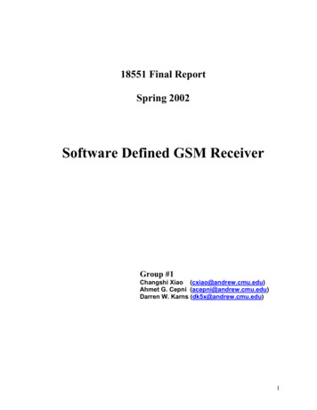
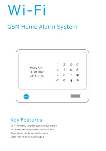
Keypad/Bluetooth/GSM Based Digital Door. 751ATmega2560 Arduino Mega: 256kB Program Space, 4 UARTs, 14 PWM, 16 Analog Inputs, 54 Digital I/O ports.Figure 4 and 5 show the top view of these boards with connection details.Fig. 4. Arduino boardFig. 5. Arduino Mega board2.4DC-DC Buck Convertor [LM 2596]We used a LM2596 buck converter as a power source converter. Input of 4V to 35V DC is given to arduinoboard and 1.25V to 30V DC, 3A given to a servo motor. It is a high performance DC to DC step-down adjustable power supply switching regulator.Fig. 6. Buck Convertor
752Umberkar et.al.2.5 Servo motorThe servo motor operates the door lock key to open or close the door lock. The torque and the speed of the motor depend upon the power supply. We are giving the power supply through the adaptor. It has a torque of 9kg/cm and speed of 0.2 sec/60 . On servo motor blades we have attached two small metal strips, between thistwo metal strips we attached the key of our lock. The key with servo motor is fixed at inside of the door lock.The key of motor rotates clock wise and anti clock wise as per the command given by arduino controller to openand close the door. To open the lock we provide the password 1234 and to close the lock 4321 from all threemodules.Fig. 7. Servo MotorFig.8. Servo Motor Mechanism with Key2.6 16x2 LCD displayWe have used 16x2 liquid crystal display (LCD) for displaying the process, like entering the password, wrongpassword detection. When Bluetooth module is connected with the GSM mobile bluetooth then the message appears on the screen.Fig. 9. LCD Display2.7 GSM SIM300It is a plug and play GSM Modem kit with a serial interface which is used to send SMS. The other GSM operations are done by controlling it through simple programming commands from arduino controller and computers.It comes with a standard RS232 interface which can be connected to interface of the arduino controller andcomputers. The modem consists of all the external circuitry required to start experimenting with the SIM300 kitlike the power regulation, external antenna, GSM SIM Holder, etc.
Keypad/Bluetooth/GSM Based Digital Door.753Features of GSM SIM300 are: Provides the industry standard serial RS232 interface for easy connection to computers and other devices. Provides serial Transistor Transistor Logic (TTL) interface for easy and direct interface to microcontroller and arduino controller. Onboard 3V Lithium Battery holder with appropriate circuitry for providing backup for the modules. Can be used for GSM based Voice communications, Data/Fax, SMS, General Packet Radio Service(GPRS) and Transmission Control Protocol/Internet Protocol (TCP/IP) stack. Comes with an onboard wire antenna for better signal reception. The SIM300 allows an adjustable serial baud rate from 1200 to 115200 bps (9600 default). Modem a low power consumption of 0.25A during normal operations and around 1A during transmission. Operating Voltage: 7 – 15V AC or DCFig. 10. GSM SIM300 Module3 Working of Door Lock system3.1 Keypad ModuleIn keypad module we have attached GSM module to TX RX pin of the Arduino kit. We have also attached servomotor, keypad and LCD to the arduino kit. The password for this module is given from keypad which is verifiedby the Arduino programme and if it gets the correct input from the keypad then it will rotate the servo motor toopen or close the door lock. We have kept two codes that is one for locking and another is for unlocking. Also aLCD displays the current status of the system for every execution of command.Fig. 11. Connection Diagram of Keypad Module
754Umberkar et.al.STARTEnter PasswordThrough KeypadYESNO1234?YESUnlock door4321?NOWrong PasswordP Lock DoorYESNOP 3Sending SMSWrong AttemptedCountedFig. 12. Flowchart for Keypad Module3.2 Bluetooth ModuleThe smart phone bluetooth application is used to lock/unlock the door lock in bluetooth module, which has arange of approximately 10m. Bluetooth HC-05 device is connected with the arduino kit. To open and close thedoor lock first we establish connection between smart phone bluetooth with arduino controller bluetooth device.As the connection has been done between these two bluetooth devices LCD show that connection is done. Thenwe enter the password from our smart phone to open or close the door lock.Fig. 13. Connection Diagram of Bluetooth Module3.3 GSM ModuleIt is most secured and most suitable module in all three modules. In which we can open and closed the door lockusing GSM mobile SMS. We can store the owner multiple GSM numbers in the arduino program. The ownersends the text message from the GSM mobile to the GSM kit connected with the arduino controller, then the arduino controller give the command to servo motor to open or close the door lock as per the password given. Ifthe password detected from unknown number for three consecutive attempts, then the arduino controller startsthe buzzer and also send a warning message of false entry at the door to the owner mobile number. As this system work with the GSM network the owner can send or receive the massage at remote location
Keypad/Bluetooth/GSM Based Digital Door.755STARTEnter PasswordThrough KeypadYESNO1234?YES4321?Unlock doorNOWrong PasswordP Lock DoorNOYESP 3Wrong AttemptedCountedSending SMSFig.14. Flowchart for Bluetooth Module.Fig. 15. Connection Diagram of GSM ModuleSTARTEnter PasswordThrough KeypadYESNO1234?YESUnlock door4321?Lock DoorNOCode not get fromAddminFig.16. Flowchart for GSM Model4 ResultsFor all three modules i.e. keypad, bluetooth and GSM we successfully operate the servo motor to open and closethe door lock. If known person attempts the three consecutive wrong password then the digital door lock systemgenerate an alert massage to GSM mobile number and also start the buzzer alarm for security alert. Figure 18show the screen shot of alert massage received on owner GSM mobile number for consecutive three wrongpassword entry done and bluetooth application screenshot is shown in figure 17.
756Umberkar et.al.Fig. 17. Bluetooth application screenshotFig. 18. Alert message in owner mobile phone.Fig. 19 Complete Setup of Door Lock Security System5 ConclusionThe prototype of the Keypad/bluetooth/GSM Based Digital Door Lock Security System was designed and implemented successfully. All modules provide security alert with buzzer alarm and SMS facility to the owner, soit is very useful to avoid the unwanted entry from our premises. We have practically demonstrated all threemodules in our lab and all are working properly. Our future work is to operate the door lock security system byface detection method which will be much more secured.
Keypad/Bluetooth/GSM Based Digital Door.757AcknowledgmentWe would like to express our special gratitude to our Dr. Vijay D. Patil (President D.Y. Patil Group), Dr.Ramesh Vasappanavara (Principal RAIT), whose contribution in stimulating suggestions and encouragement.Special thanks to our Dr. Vishwesh Vyawahare (HOD Department of Electronics Engineering) for motivation ofthis work.References[1] National Crime Records Bureau, Statistics 2011, htpp://www.ncrb.nic.in[2] Adnan Ibrahim, Afhal Paravath, Aswin P. K., Shijin Mohammed Iqbal and Shaeez Usman Abdulla,“GSM Based Digital Door Lock Security System”, IEEE International Conference on Power, Instrumentation, Control and Computing (PICC) 978-1-4673-8072-0/15 IEEE 2015.[3] Pratiksha Misal, Madhura Karule, Dhanshree Birdawade, Anjali Deshmukh, Mrunal Pathak,”DoorLocking/Unlocking System using SMS Technology with GSM/GPRS Services”,International Journalof Electronics Communication and Computer Engineering Volume 5, Issue (4) July, Technovision2014, ISSN 2249071X, April 2014[4] Ushie James Ogri, Donatus Enang, Bassey Okwong, Akaiso Etim, “Design and construction of DoorLocking Security System Using GSM”, International Journal Of Engineering And Computer ScienceISSN:2319-7242 Volume 2 Issue 7,Page No. 2235-2257, July 2013[5] John Mallory, “Central Monitor for Home Security System”, US4581606A, Apr8, 1986.[6] Website: http://www.alarm.org/HomeSafety/FastFacts.aspx[7] Website: http://airef.org/burglars-confirm-value-of-alarms
Pratiksha [3], described a home security system with the GSM/GPRD technology services to achieve controlling of door lock by short message service (SMS). Also Adnan Ibrahim discussed the . Arduino is an open source platform used for building electronics project. Arduino is often referred as a micro-controller. Different types of Arduino and .