Transcription
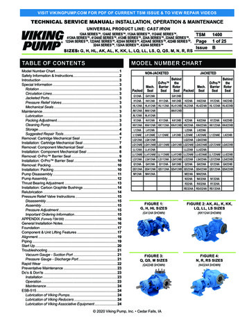
VISIT VIKINGPUMP.COM FOR PDF OF CURRENT TSM ISSUE & TO VIEW REPAIR VIDEOSTECHNICAL SERVICE MANUAL: INSTALLATION, OPERATION & MAINTENANCEUNIVERSAL PRODUCT LINE: CAST IRON124A SERIES , 124AE SERIES , 1124A SERIES , 1124AE SERIES ,4124A SERIES , 4124AE SERIES , 4124B SERIES , 224A SERIES , 224AE SERIES ,1224A SERIES , 1224AE SERIES , 4224A SERIES , 4224AE SERIES , 4224B SERIES ,324A SERIES , 1324A SERIES , 4324A SERIES SIZES: G, H, HL, AK, AL, K, KK, L, LQ, LL, LS, Q, QS, M, N, R, RSTABLE OF CONTENTSTSMPageIssue14001 of 25BMODEL NUMBER CHARTModel Number Chart.1Safety Information & Instructions.2Introduction.3Special Information.3Rotation.3Circulation Lines.3Jacketed Ports.3Pressure Relief Valves.3Mechanical Seals.3Maintenance.3Lubrication.3Packing Adjustment.3Cleaning Pump.3Storage.4Suggested Repair Tools.4Removal: Cartridge Mechanical Seal.7Installation: Cartridge Mechanical Seal.7Removal: Component Mechanical Seal.8Installation: Component Mechanical Seal.8Removal: O-Pro Barrier Seal.9Installation: O-Pro Barrier Seal.10Removal: Packing.10Installation: Packing.10Pump Disassembly. 11Pump Assembly.12Thrust Bearing Adjustment.13Installation: Carbon Graphite Bushings.14Relubrication.14Pressure Relief Valve Instructions.15Disassembly.15Assembly.15Pressure Adjustment.15Important Ordering Information.15APPENDIX (Formerly TSM 000).16General Installation Notes.16Foundation.17Component & Unit Lifting Features.17Alignment.19Piping.19Start Up.20Troubleshooting.21Vacuum Gauge - Suction Port.21Pressure Gauge - Discharge Port.21Rapid Wear .22Preventative Maintenance.23Do’s & 24ESB-515.24Lubrication of Viking Pumps.24Lubrication of Viking Reducers.24Lubrication of Viking Associative H124AH4124AJACKETEDBehindO-Pro theBarrier RotorMech.SealSeal Packed SealBehindO-Pro theBarrier 224BHL124A HL4124A HL1124A HL4124B HL224A HL4224A HL1224A HL4224BAK124A AK4124AAK4124BAL124A 24BKK124A KK4124A KK1124A KK4124B KK224A KK4224A KK1224A KK4224BL124AL4124AL124AEL4124AE L1124AEL4124BLQ124A LQ4124AL224AL4224AL224AEL4224AE L1224AEL4224BLQ224A LQ4224ALQ124AE LQ4124AE LQ1124AE LQ4124B LQ224AE LQ4224AE LQ1224AE LQ4224BLL124ALL4124ALL224ALL4224ALL124AE LL4124AE LL1124AE LL4124B LL224AE LL4224AE LL1224AE LL4224BLS124A LS4124A LS1124A LS4124B LS224A LS4224A LS1224A 24BQS124A QS4124A QS1124A QS4124B QS224A QS4224A QS1224A AR4324AR1324ARS324A RS4324A RS1324AFIGURE 1:G, H, HL SIZESFIGURE 2: AK, AL, K, KK,LQ, LL, LS SIZESFIGURE 3:Q, QS, M SIZESFIGURE 4:N, R, RS SIZES(G4124A SHOWN)(Q4224B SHOWN) 2020 Viking Pump, Inc. Cedar Falls, IA(KK1124A SHOWN)(N4324A SHOWN)
SAFETY INFORMATION & INSTRUCTIONSIMPROPER INSTALLATION, OPERATION OR MAINTENANCEOF PUMP MAY CAUSE SERIOUS INJURY OR DEATH, AND/ORRESULT IN DAMAGE TO PUMP AND/OR OTHER EQUIPMENT.VIKING’S WARRANTY DOES NOT COVER FAILURE DUE TOIMPROPER INSTALLATION, OPERATION OR MAINTENANCE.THIS INFORMATION MUST BE FULLY READ BEFOREBEGINNING INSTALLATION, OPERATION OR MAINTENANCEOF PUMP, AND MUST BE KEPT WITH PUMP. PUMP MUST BEINSTALLED, OPERATED AND MAINTAINED ONLY BY SUITABLYTRAINED AND QUALIFIED PERSONS.THE FOLLOWING SAFETY INSTRUCTIONS MUST BE FOLLOWED AND ADHERED TO AT ALL TIMES. DANGER FAILURE TO FOLLOW THE INDICATEDINSTRUCTION MAY RESULT IN SERIOUS INJURYOR DEATH. DANGERBEFORE opening any liquid chamber (pumping chamber,reservoir, relief valve adjusting cap fitting, etc.) be sure that: Any pressure in the chamber has been completely ventedthrough the suction or discharge lines or other appropriateopenings or connections. The pump drive system (motor, turbine, engine, etc.) hasbeen “locked out” or otherwise been made non-operational,so that it cannot be started while work is being done onthe pump. You know what material the pump has been handling,have obtained a material safety data sheet (MSDS) forthe material, and understand and follow all precautionsappropriate for the safe handling of the material. DANGERBEFORE operating the pump, be sure all drive guards are inplace. DANGERDO NOT operate pump if the suction or discharge piping isnot connected. DANGERDO NOT place fingers into the pumping chamber, or itsconnection ports, or into any part of the drive train if there isany possibility of the pump shaft being rotated. WARNINGDO NOT exceed the pumps rated pressure, speed, andtemperature, or change the system/duty parameters fromthose the pump was originally supplied, without confirming itssuitability for the new service. WARNINGBEFORE operating the pump, be sure that: It is clean and free from debris. All valves in the suction and discharge pipelines are fullyopened. All piping connected to the pump is fully supported andcorrectly aligned with the pump. Pump rotation is correct for the desired direction of flow.TSM 1400 Issue B Page 2 of 25 WARNING IN ADDITION TO SERIOUS INJURY OR DEATH,FAILURE TO FOLLOW THE INDICATED INSTRUCTION MAYCAUSE DAMAGE TO PUMP AND/OR OTHER EQUIPMENT WARNINGINSTALL pressure gauges/sensors next to the pump suctionand discharge connections to monitor pressures. WARNINGUSE extreme caution when lifting the pump. Suitable liftingdevices should be used when appropriate. Lifting eyesinstalled on the pump must be used only to lift the pump, notthe pump with drive and/or base plate. If the pump is mountedon a base plate, the base plate must be used for all liftingpurposes. If slings are used for lifting, they must be safely andsecurely attached. For weight of the pump alone (which doesnot include the drive and/or base plate) refer to the VikingPump product catalog. DANGERDO NOT attempt to dismantle a pressure relief valve that hasnot had the spring pressure relieved or is mounted on a pumpthat is operating. DANGERAVOID contact with hot areas of the pump and/or drive.Certain operating conditions, temperature control devices(jackets, heat-tracing, etc.), improper installation, improperoperation, and improper maintenance can all cause hightemperatures on the pump and/or drive. WARNINGTHE PUMP must be provided with pressure protection. Thismay be provided through a relief valve mounted directly onthe pump, an in-line pressure relief valve, a torque limitingdevice, or a rupture disk. If pump rotation may be reversedduring operation, pressure protection must be provided onboth sides of pump. Relief valve adjusting screw caps mustalways point towards suction side of the pump. If pumprotation is reversed, position of the relief valve must bechanged. Pressure relief valves cannot be used to controlpump flow or regulate discharge pressure. For additionalinformation, refer to Appendix, General Installation Notes,item 5 on Pressure Protection or contact your Viking Pump representative for Engineering Service Bulletin ESB-31. WARNINGTHE PUMP must be installed in a manner that allows safeaccess for routine maintenance and for inspection duringoperation to check for leakage and monitor pump operation. 2020 Viking Pump, Inc. Cedar Falls, IA
INTRODUCTIONPRESSURE RELIEF VALVESThe illustrations used in this manual are for identificationpurposes only and cannot be used for ordering parts.Obtain a parts list from your Viking Pump representative.Always give a complete name of part, part number andmaterial with the model number and serial number of pumpwhen ordering repair parts. The unmounted pump or pumpunit model number and serial number are on the nameplate.This manual only applies to the pump models specified in the"Model Number Chart" on page 1. Pump specifications andrecommendations are listed in the Catalog Sections, whichare available at vikingpump.com.SPECIAL INFORMATIONROTATIONViking pumps can operate equally well in a clockwise orcounter-clockwise rotation; however, some constructionsmay require modifications. Consult your Viking Pump representative if unsure. Shaft rotation determines whichport is suction and which is discharge. Suction port is wherepumping elements (gear teeth) come out of mesh.If pump rotation is reversed during operation, pressureprotection must be provided on both sides of pump.Relief valve adjusting screw cap must always point towardssuction side of pump. If pump rotation is reversed, removepressure relief valve and turn end for end.CIRCULATION LINESThis equipment (not utilized on all pumps) must be connectedproperly. Packed pumps typically have a flush line frompacking chamber to discharge port. Mechanical sealpumps typically have a suckback line from seal chamber tosuction port. If pump rotation is reversed, be sure circulationconnections are connected to the suction or discharge port asnoted above to avoid excessive leakage or damage to pump.If pump is handling heated product, be sure circulation line isinsulated to assure continued flow.JACKETED PORTSJackets are utilized to heat (or cool) the pump and liquid in thepump prior to startup. Not all pumps have ports for jacketing.Jacketing port locations vary by model.FIGURE 5: RELIEF VALVE POSITIONDischargeSuction1. Viking pumps are positive displacement pumps and must beprovided with some sort of pressure protection. This may be arelief valve mounted directly on the pump, an inline pressurerelief valve, a torque limiting device or a rupture disk.2. There are relief valve options available on those pumpmodels designed to accept a relief valve. Options mayinclude a jacketed relief valve or return to tank relief valve.3. If pump rotation is reversed during operation, pressureprotection must be provided on both sides of pump.4. Relief valve adjusting screw cap must always pointtowards suction side of pump, see "Figure 5" on page15. If pump rotation is reversed, remove pressure reliefvalve and turn end for end.5. Pressure relief valves cannot be used to control pump flowor regulate discharge pressure.For additional information on pressure relief valves, Refer toAppendix, General Installation Notes, item 5 on PressureProtection or contact your Viking Pump representative forEngineering Service Bulletin ESB-31.MECHANICAL SEALSExtra care should be taken in repair of pumps withmechanical seals. Be sure to read and follow all specialinstructions supplied with your pump.MAINTENANCEThese pumps are designed for long, trouble-free service lifeunder a wide variety of application conditions with a minimumof maintenance. The points listed below will help provide longservice life.LUBRICATIONExternal lubrication must be applied slowly with a handgun to all lubrication fittings every 500 hours of operationwith multi-purpose grease, NLGI # 2. Contact your VikingPump representative with specific lubrication questions.Engineering Service Bulletin ESB-515 is located in theAppendix for standard grease thickener types used by Vikingto check compatibility. Applications involving very high or lowtemperatures will require other types of lubrication. O-Pro seals should also be greased every 500 hours of operation witha lubricating fluid compatible with the process fluid.PACKING ADJUSTMENTNew packed pumps require initial packing adjustment tocontrol leakage as packing “runs in”. Make initial adjustmentscarefully and do not over -tighten packing gland. After initialadjustment, inspection will reveal need for packing glandadjustment or packing replacement. Contact your VikingPump representative for Engineering Service Bulletin ESB521 regarding repacking pump.CLEANING PUMPKeep pump as clean as possible. This will facilitate inspection,adjustment and repair work and help prevent overlooking adirt covered grease fitting.Relief Valve Adjusting Screw Cap 2020 Viking Pump, Inc. Cedar Falls, IATSM 1400 Issue B Page 3 of 25
STORAGEIf pump is to be stored, or not used for six months or more,pump must be drained and a light coat of non-detergent SAE30 weight oil must be applied to all internal pump parts.Lubricate fittings and apply grease to pump shaft extension.Viking suggests rotating pump shaft by hand one completerevolution every 30 days to circulate the oil. Tighten all pumpassembly bolts before putting pump in service after being stored.SUGGESTED REPAIR TOOLSThe following tools must be available to properly repair thesepumps. These tools are in addition to standard mechanics’ toolssuch as open-end wrenches, pliers, screwdrivers, etc. Most ofthe items can be obtained from an industrial supply house.1. Soft Headed hammer2. Allen wrenches (some mechanical seals and set collars)3. Packing hooks, flexible (packed pumps)5. Seal installation sleeves for mechanical and O-Pro Seals2-751-001-730 for 0.75 inch seal; G pumps2-751-002-730 for 1.125 inch seal; H-HL2-751-003-730 for 1.4375 inch seal; AK-LL pumps2-751-005-630 for 2.4375 inch seal; Q-M pumps2-751-006-630 for 3.4375 inch seal; N pumps2-751-010-630 for 4.5000 inch seal; R & RS pumpsNo sleeve needed for LS pumps or L, LQ, LL "AE" pumps6. Bearing locknut spanner wrenchSource: #471 J. H. Williams & Co. or equal; H-LL pumpsSource: #472 J. H. Williams & Co. or equal; LS-M pumps7. Spanner wrench, adjustable pin type for bearing housingSource: #482 J. H. Williams & Co. or equal; H-M pumpsSupplied with pump; N-RS pumps8. Brass or plastic bar9. Arbor press4. Jack bolts (O-Pro barrier removal)2-150-158-255-00; H-LS2-151-006-255-00; Q-QS2-150-139-255-00; N-RSContact your Authorized Viking Pump stocking distributor for available seal and rebuild kitsFIGURE 6: EXPLODED VIEW (G, H, HL, AK, AL, K, KK, L, LQ, LL, LS SIZES) —124A SERIES , 124AE SERIES , 1124A SERIES , 1124AE SERIES , 4124A SERIES , 4124AE SERIES ,224A SERIES , 224AE SERIES , 1224A SERIES , 1224AE SERIES , 4224A SERIES ,4224AE SERIES NOTE: IMAGE IS REPRESENTATIVE ONLY2626A12BItemName Of PartItem1LocknutLockwasherEnd CapBearing Spacer Collar (Outer)Lip SealBall BearingBearing HousingBearing Spacer Collar (Inner)Ring, Half Round (Not H, HL)Grease FittingGrease FittingPacking / Mechanical Seal GlandPacking / Mechanical Seal / O-Pro Gland NutCapscrews, Seal Gland / O-Pro BarrierDynamic O-Ring (Qty 2 Req'd)18B2345678111212B15161718ATSM 1400 Issue B Page 4 of 2518C191919192021252626A27282930Name Of PartItemInner Static O-RingOuter Static O-RingCartridge SealPackingO-Pro Barrier SealMechanical SealPacking Retaining WasherMechanical Seal CollarBracket Bushing (not used with O-Pro Barrier)Pressure Relief FittingReducer BushingBracket and Bushing AssemblyCapscrew for BracketBracket GasketPipe Plug31353637383940414243454647Name Of PartCasing (Tapped or Flanged)Head GasketRotor and Shaft AssemblyIdler and Bushing AssemblyIdler BushingIdler PinHead and Idler Pin AssemblyO-Ring for Jacket Head PlateJacket Head PlateCapscrew for HeadRelief Valve GasketCapscrew for ValveInternal Relief Valve 2020 Viking Pump, Inc. Cedar Falls, IA
Contact your Authorized Viking Pump stocking distributor for available seal and rebuild kitsFIGURE 7: EXPLODED VIEW (G, H, HL, AK, AL, K, KK, L, LQ, LL, LS SIZES) — 4124B SERIES , 4224B SERIES NOTE: IMAGE IS REPRESENTATIVE 243454746191130Item12345678111218Name Of PartItemLocknutLockwasherEnd CapBearing Spacer Collar (Outer)Lip SealBearing (Ball or Tapered Roller)Bearing HousingBearing Spacer Collar (Inner)Ring, Half Round (Not Q, QS)Grease FittingLip Seal1925262728293031353637Name Of PartMechanical SealBracket BushingPressure Relief Fitting for BracketBracketCapscrew for BracketBracket GasketPipe PlugCasing (Tapped or Flanged)Head GasketRotor and ShaftIdlerItemName Of PartIdler BushingIdler PinHead and Idler Pin AssemblyO-Ring for Jacket Head Plate (4224B)Jacket Head Plate (4224B)Capscrew for HeadRelief Valve GasketCapscrew for Relief ValveInternal Relief Valve383940414243454647FIGURE 8: EXPLODED VIEW (Q, QS, M SIZES) —124A SERIES , 1124A SERIES , 4124A SERIES , 224A SERIES , 1224A SERIES , 4224A SERIES NOTE: IMAGE IS REPRESENTATIVE ONLY12B2626AItemName Of PartItem1LocknutLockwasherEnd Cap for Bearing HousingBearing Spacer Collar (Outer)Lip Seal for Bearing Housing (2 Req’d)Roller Bearing (2 Req’d)Bearing HousingBearing Spacer Collar (Inner)Grease FittingGrease FittingPacking GlandPacking Gland Nut / O-Pro Barrier NutPacking Gland WasherPacking Gland Capscrew / O-Pro Barrier CapscrewsRetainer for Packing BoltsDynamic O-Rings (Qty 2 Req'd)18B23456781212B151616A1717A18A 2020 Viking Pump, Inc. Cedar Falls, IA18C1919191920252626A2728293030A31Name Of PartItemInner Static O-RingOuter Static O-RingCartridge SealPackingO-Pro Barrier SealMechanical SealPacking Retaining WasherBracket Bushing (not used with O-Pro Barrier)Pressure Relief FittingReducer BushingBracket and Bushing AssemblyCapscrew for BracketBracket GasketPipe PlugPipe PlugCasing3435363738394043444546475152Name Of PartPipe Flange GasketHead GasketRotor and Shaft AssemblyIdler and Bushing AssemblyIdler BushingIdler PinHead and Pin AssemblyStud for HeadNut for HeadRelief Valve GasketCapscrew for Relief ValveInternal Relief ValveStud for FlangesNut for FlangesTSM 1400 Issue B Page 5 of 25
Contact your Authorized Viking Pump stocking distributor for available seal and rebuild kitsFIGURE 9: EXPLODED VIEW (N, R, RS SIZES) — 324A SERIES , 1324A SERIES , 4324A SERIES NOTE: IMAGE IS REPRESENTATIVE ONLY1918A12B18C18B18A2626AItemName Of PartItem1LocknutLockwasherEnd Cap for Bearing HousingLip Seal for Bearing Housing (2 Req’d)Bearing Spacer CollarRoller Bearing (2 Req’d)Bearing HousingGrease FittingGrease FittingPacking GlandPacking Gland Nut / O-Pro Barrier NutPacking Gland WasherPacking Gland Stud / O-Pro Barrier StudDynamic O-Ring (Qty 2 Req'd)Inner Static O-RingOuter Static O-Ring192345671212B151616A1718A18B18CTSM 1400 Issue B Page 6 of 2519192023252626A272828A293030A3135Name Of PartPackingO-Pro Barrier SealMechanical SealPacking Retaining WasherSeal PlateBracket BushingPressure Relief FittingReducer BushingBracket and Bushing AssemblyStud for BracketNut for BracketBracket GasketPipe PlugPipe PlugCasingHead GasketItem3637383940434445464747A51525356Name Of PartRotor and Shaft AssemblyIdler and Bushing AssemblyIdler BushingIdler PinHead and Idler Pin AssemblyStud for HeadNut for HeadRelief Valve GasketCapscrew for Relief ValveInternal Relief ValveCover PlatesStuds for FlangesNut for FlangesLocating PinFlush / Suckback Line 2020 Viking Pump, Inc. Cedar Falls, IA
DANGER !Before opening any Viking pump liquid chamber(pumping chamber, reservoir, relief valve adjusting capfitting, etc.) be sure:1. That any pressure in the chamber has beencompletely vented through the suction or dischargelines, or other appropriate openings or connections.2. That the driving means (motor, turbine, engine, etc.)has been “locked out” or made non-operational, so thatit cannot be started while work is being done on pump.3. That you know what liquid the pump has been handlingand the precautions necessary to safely handle theliquid. Obtain a material safety data sheet (MSDS) forthe liquid to be sure these precautions are understood.Failure to follow above listed precautionary measuresmay result in serious injury or death.REMOVAL: CARTRIDGEMECHANICAL SEALCartridge mechanical seals are designed so that they may bereplaced with minimal pump and piping disassembly1. Insert brass or plastic bar through port opening betweenrotor teeth to keep shaft from turning. Bend up tang oflockwasher and with a spanner wrench, remove locknutand lockwasher from shaft.2. Loosen two set screws in the face of the bearing housingand remove the bearing housing assembly from thebracket.3. Remove the pair of half round rings (AK, AL, K, KK, L, LQ,LL, LS sizes only) under the inner spacer collar from theshaft.4. Remove any flush or barrier fluid tubes connected to theseal gland.5. Replace or turn centering clips to original position.6. Loosen setscrews on the seal collar to free the cartridgeseal from the shaft.7. Loosen and remove the two nuts holding the seal to thepump and slide the cartridge seal out through the bearinghousing opening.If the pump is to be disassembled further, refer to "PumpDisassembly" on page 11.INSTALLATION: CARTRIDGEMECHANICAL SEAL1. NOTE: Burrs left on shaft can damage O-ring on sealsleeve during installation. Inspect shaft for burrs andremove any found with a fine grade of emery cloth.2. Clean rotor shaft and face of seal chamber.3. Place tapered installation sleeve on shaft. Coat rotorshaft, tapered installation sleeve, and O-ring in the insidediameter of cartridge seal sleeve with a generous amountof P-80 or equivalent. See "Figure 10" on page 7.4. Slide cartridge seal over installation sleeve on shaftuntil it contacts the seal chamber face. Remove taperedinstallation sleeve from shaft.5. Place pair of half round rings in groove on shaft (AK, AL,K, KK, L, LQ, LL, LS sizes only) and turn bearing housingassembly into bracket.6. Put lockwasher and locknut on shaft. Tighten locknut andbend one tang of lockwasher into slot of locknut. See"Table 3" on page 13.7. Adjust pump end clearance, refer to "Thrust BearingAdjustment" on page 13.8. Insert gland capscrews and secure gland to bracket faceusing washers and nuts.NOTE: turn shaft several turns while gland is loose tocenter seal; then tighten nuts enough to compress glandgasket. Tighten only enough to contain leakage and not todistort gland.9. Tighten setscrews on seal drive collar to shaft. Remove orturn centering clips out of the way so as to clear the drivecollar.10. Turn shaft by hand or jog motor to check drive collar forrunout.11. Connect circulation line or vent stuffing box seals withoutcirculation line until liquid is present on start up.NOTE: For maximum seal life, circulation line shouldbe used. DANGER !Before starting pump, be sure all drive equipment guardsare in place.Failure to properly mount guards may result in seriousinjury or death.FIGURE 10Tapered Installation SleeveShaftNOTE: Coat rotor shaft, tapered installationsleeve and inner diameter of mechanical sealwith P-80 or equivalent before assembly.P-80 is a registered trademark of International Products Corporation 2020 Viking Pump, Inc. Cedar Falls, IATSM 1400 Issue B Page 7 of 25
DANGER !Before opening any Viking pump liquid chamber(pumping chamber, reservoir, relief valve adjusting capfitting, etc.) be sure:1. That any pressure in the chamber has beencompletely vented through the suction or dischargelines, or other appropriate openings or connections.2. That the driving means (motor, turbine, engine, etc.)has been “locked out” or made non-operational, so thatit cannot be started while work is being done on pump.3. That you know what liquid the pump has been handlingand the precautions necessary to safely handle theliquid. Obtain a material safety data sheet (MSDS) forthe liquid to be sure these precautions are understood.Failure to follow above listed precautionary measuresmay result in serious injury or death.REMOVAL: COMPONENTMECHANICAL SEALElastomeric bellows, elastomeric o-ring and PTFE wedgeseals generally require pump disassembly to be replaced(refer to "Pump Disassembly" on page 11).1. Insert brass or plastic bar through port opening betweenrotor teeth to keep shaft from turning. Bend up tang oflockwasher and with a spanner wrench, remove locknutand lockwasher from shaft.2. Loosen two set screws in the face of the bearing housingand remove the bearing housing assembly from thebracket.3. Remove the pair of half round rings (AK, AL, K, KK, L, LQ,LL, LS sizes only) under the inner spacer collar from theshaft.4. Loosen nuts and remove seal holder, seal seat and sealgasket(s).5. Loosen setscrews in mechanical seal rotary member.NOTE: Circulation line and/or plugs will need to beremoved to access setscrews.If changing the mechanical seal is the extent of themaintenance to be performed, then the rotor shaftassembly only needs to be moved far enough to dislodgethe rotary member of the seal. (Not applicable for 4124BSeries & 4224B Series pumps)6. Drive the rotor/shaft assembly out of the casing until therotor teeth extend past the face of the casing.7. 4124B Series & 4224B Series Only: Remove the rotorshaft assembly completely from the pump. Remove therotary member of the mechanical seal from the rotor shaft.Remove the seal seat from the bracket.8. Push the rotor/shaft assembly back into the casing. Therotary member of the seal should now be pushed farenough down the shaft for easy removal.INSTALLATION: COMPONENTMECHANICAL SEAL1. Clean rotor shaft and seal housing bore. Make sure theyare free of dirt, grit and scratches. Gently radius leadingedge of the shaft diameter over which seal is to be placed.Never touch mechanical seal faces with anything exceptclean hands or clean cloth. Minute particles can scratchthe seal faces and cause leakage.2. Place tapered installation sleeve on the shaft. Coattapered sleeve and inside of the rotary member with agenerous quantity of P-80 or equivalent. Grease is notrecommended. Start rotary member on shaft and overtapered sleeve. See "Figure 11" on page 8.3. Push shaft until rotor contacts head. Move rotary memberso setscrews are directly below seal access holes on sideof bracket. Tighten all setscrews securely to shaft. Someseals are equipped with holding clips which compress theseal springs. Remove holding clips to release springs afterseal is installed on shaft.4124B Series and 4224B Series Only:If the seal uses setscrews to secure the seal to theshaft, tighten the setscrews once the seal is in place.Move rotary member all the way on the rotor shaft until itis against the rotor hub.If the seal uses a single spring and drive pin, placeseal spring on shaft against rotor hub (see "Figure 12"on page 9). Slide rotary member, lapped contactsurface facing away from spring, over installation sleeveon shaft until it is against spring. Slot in the seal mustline up with drive pin in the shaft. Do not compressspring.Some PTFE seals are equipped with holding clips whichcompress the seal springs. Remove holding clips torelease springs after seal is installed on shaft.4. FOR “O-RING” GASKET TYPE MECHANICAL SEALSEAT: Lubricate outer diameter of O-Ring seal gasketwith P-80 or equivalent. Press seal seat in to bore untilback, unlapped face, is flush with bore. Install seal holder,capscrews, and nuts and tighten securely. Removetapered installation sleeve.FOR “CLAMPED-IN” TYPE MECHANICAL SEAL SEAT:Flush sealing faces of both rotary member and seal seatwith oil and install seal seat and seat gasket over end ofshaft against machined bracket face. Install other sealgasket, seal holder, capscrews, and nuts and tightensecurel
with multi-purpose grease, NLGI # 2. Contact your Viking Pump representative with specific lubrication questions. Engineering Service Bulletin ESB-515 is located in the Appendix for standard grease thickener types used by Viking to check compatibility. Applications involving very high or low temperatures will require other types of lubrication.