Transcription
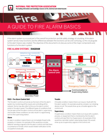
SECTION 16732FIRE ALARM, DETECTION AND NOTIFICATION SYSTEMPART 1 – GENERAL1.01SUMMARYA. The work covered by this Section of the Specification shall include all labor, equipment, materialsand services to furnish and install a complete fire alarm system.1. Fire Alarm Control Panel.2. Remote Annunciator.3. Manual pull stations.4. Smoke detectors.5. Heat detectors.6. Fire Alarm System Interface Controls- Proprietary supervising station, magnetic door/cardaccess release override, and air handling system.7. Notification appliances.8. Air handling systems shutdown control.9. Magnetic door holder release.10. Fire Suppression Supervision- Wet pipe, dry pipe, deluge valve, pre-action System, kitchenhood, clean agent and Halon system monitoring.B. Related Sections:1. Section 08331 – Overhead Coiling Doors.2. Section 08710 – Finish Hardware.3. Section 13905 – Fire Protection, Suppression and Alarm.4. Section 14200 – Hydraulic Elevators.5. Section 14240 – Traction Elevators.6. Section 14300 – Heavy-Duty Escalator.7. Section 16120 – Wire, Cable and Busways.8. Section 16130 – Raceways, Boxes and Cabinets.9. Section 16705 – Communications Standard Specifications – Equipment & Material.10. Section 16706 – Communications Systems Submittals & Services.11. Section 16707 – Communications Systems Quality Assurance & Testing.12. Section 16710 – Communications Grounding.Section 16715 – Communications ElectricalPower Distribution.13. Section 16733 – Communications – Kiosk Systems.Page 1 of 2016732October 1, 2014REV 01.01
14. Section 16925 – ATC – Data Transmission System.1.02REFERENCESA. The system and all components shall be approved by insurance provider for use in fire protectionsystems and compliant with all insurance provider guidelines. If insurance provider approval is notavailable, insurance representatives must be consulted to ensure system is acceptable andcomponents must at least be listed by Underwriters Laboratories, Inc. for use in fire protectivesignaling systems.B. The installation shall comply with:1. State and Local Building and Fire Codes.2. Americans with Disabilities Act (ADA).3. NFPA 70 – National Electrical Code.4. NFPA 72 – National Fire Alarm and Signaling Code.5. Local and State Authorities Having Jurisdiction.6. NFPA 130 - Standard for Fixed Guideway Transit and Passenger Rail Systems7. NFPA 70 - National Electrical Code8. NFPA 101 - Life Safety Code1.03SUBMITTALSA. Provide a list of all types of equipment and components provided. This shall be incorporated aspart of a Table of Contents, which shall also indicate the manufacturer’s part number, thedescription of the part, and the part number of the manufacturer’s product data sheet on which theinformation can be found. See Division 1 for specific details about submissions.B. Provide a Sequence of Operation matrix. The sequence of operation shall be building specific,and shall provide individual sequences for every type of alarm, supervisory or trouble conditionwhich may occur as part of normal or off-normal system use.C. Provide manufacturer’s original printed product data, catalog cuts and description of any specialinstallation procedures. Photocopied and/or illegible product data sheets shall not be acceptable.All product datasheets shall be highlighted or stamped with arrows to indicate the specificcomponents being submitted for approval.D. Provide manufacturer’s installation instruction manual for specified system.E. Provide samples of various items when requested.F. Provide copy of state License to perform such work.G. Provide copies of NICET Level IV Fire Alarm certifications for a minimum of two (2) techniciansassigned to this project also responsible for Fire Alarm Control Panel (FACP) programming.H. Provide shop drawings as follows:1. Coversheet with project name, address and drawing index.2. General notes drawing with peripheral device back-box size information, part numbers, devicemounting height information, and the names, addresses, point of contact, and telephonenumbers of all contact project team members.Page 2 of 2016732October 1, 2014REV 01.01
3. Building specific device riser diagram, which individually depicts all control panels,annunciators, addressable devices, and notification appliances. Include a specific, proposedpoint descriptor above each addressable device. Include a specific discrete point address thatshall correspond to address depicted on the device layout floor plans. Drawing shall providewire specifications, and wire tags shown on all conductors depicted on the riser diagram. Allcircuits shall have designations that shall correspond with those required on the control paneland floor plan drawings. End-of-line resistors (and values) shall be depicted.4. Control panel termination drawing(s). Include internal component placement and all internaland field termination points. Drawing shall provide a detail indicating where conduitpenetrations shall be made, so as to avoid conflicts with internally mounted batteries. Foreach additional data gathering panel, a separate control panel drawing shall be provided,which clearly indicates the designation, service and location of the control enclosure. End-ofline resistors (and values) shall be depicted.5. Building specific device wiring diagram drawing(s) shall be provided which depict all systemcomponents, and their respective field wiring termination points. Wire type, gauge, and jacketshall also be indicated. When an addressable module is used in multiple configurations formonitoring or controlling various types of equipment, different device typical diagrams shall beprovided. End-of-line resistors (and values) shall be depicted.6. See section 3.05 CLOSEOUT ACTIVITIES for other documents relating to this section.I.Battery calculations shall be provided on a per power supply/charger basis. These calculationsshall clearly indicate1. The quantity of devices2. The device part numbers3. The supervisory current draw4. The alarm current draw5. Totals for all categories, and the calculated battery requirements (which reflect a 20%DEGRADE, for 24 hour supervisory, 5 minute alarm operation).6. Battery calculations shall also reflect all control panel components, remote annunciator,and auxiliary relay current draws.J.Scale drawing sets shall be submitted along with the submittal book. These drawings shall be 22”x 34” and of a sufficient resolution to be completely legible when reduced to 11” x 17” size.K. Written proof of proper disposal by the installing contractor shall be required prior to release ofoutstanding retainage.L. Turnover of all software database hard/soft copies to WMATA prior to the end of the one (1) yearwarranty period (or period as amended earlier in this specification). This shall include all possibleprogramming software logs, exported project files, hard copies of all device maps, the revisionnumber of the version of programming utility used, and all required passwords. This informationshall be provided to WMATA on a flash drive.1.04QUALITY ASSURANCEA. Qualifications: Company specializing in installation of work in this Section with minimum of threeyears documented experience, approved by manufacturer.B. System Standards:1. NFPA 72.Page 3 of 2016732October 1, 2014REV 01.01
2. CEC, Article 760.C. Design criteria:1. Comply with all system standards.2. Meet all requirements of fire authorities having jurisdictions.3. The Building Electronics contractor shall provide complete fire detection and alarm systemdesign, wiring diagrams, interphase wiring diagrams, and operational details.1.05DELIVERY, STORAGE, AND HANDLINGA. Protect equipment delivered and placed in storage from the weather, humidity and temperaturevariation, dirt, dust and any other contaminants.B. Project staging may be provided at stakeholders’ convenience. A staging area is not guaranteed.1.06RELATED WORKA. The fire alarm and detection system provides controls to and/or interfaces with the followingsystems and equipment:1. Ventilation fans.2. Fire suppression systems.3. Elevators and escalators.4. Data Transmission Systems (DTS).5. Automatic Fare Collection (AFC).6. Automatic public address.7. Fire standpipe systems.8. Clean agent systems.9. Combustible gas detection.10. Carbon monoxide detection.PART 2 – PRODUCTS2.01ACCEPTABLE MANUFACTURERSA. Manufacturers capable of meeting the system requirements of Part 2 of this specification.B. New fire alarm equipment shall be compatible with the existing W MATA fire alarm equipment.New equipment shall be able to provide two-way command and control communication betweenan EST Fireworks head end and all protected premise fire alarm control panels and field devices.2.02EQUIPMENTA. Fire Alarm Control Panel (FACP)1. The fire alarm control panel(s) shall be an Edwards EST-3 or equivalent. System devices(notification appliances, pull stations, smoke and heat detectors, etc.) shall be compatible withone another. All components will be labeled “FM approved” for the use of fire alarm systemsin this area of the United States of America.Page 4 of 2016732October 1, 2014REV 01.01
2. Fire alarm control panel cabinet shall be 3-CAB series or equivalent. Cabinet shall bemanufactured from #14 AWG cold rolled steel with a gray baked enamel finish. Operatingcontrols shall be located behind a locked door with a viewing window.3. Fire alarm control panel enclosures shall have engraved labels indicating, “FIRE ALARMSYSTEM”, and the areas of the building served by that panel.4. All control modules shall be labeled, and all zone locations shall be identified.5. Conventional fire alarm panel supporting 1/3/5/10 initiating device circuits and 1 through 4notification appliance, Class B circuits as required in the space. If the panel is not a slaveprovide Digital Alarm Communicator Transmitter (DACT) for off premises communication.6. The system shall store all basic system functionality and job specific data in non-volatilememory. All site specific and operating data shall survive a complete power failure intact.Passwords shall protect any changes to system operations.7. The system shall have built-in automatic system programming to automatically address andmap all system devices attached to the main controller. A minimum default single stage alarmsystem operation shall be supported with alarm silence, event silence, drill, lamp test, andreset common controls.8. The system shall support distributed processor intelligent detectors with the followingoperational attributes: integral multiple differential sensors, automatic device mapping,electronic addressing, environmental compensation, pre-alarm, dirty detector identification,automatic day/night sensitivity adjustment, normal/alarm LEDs, relay bases, sounder basesand isolator bases.9. The system shall use full digital communications to supervise all addressable loop devices forplacement, correct location, and operation. It shall allow swapping of “same type” deviceswithout the need of addressing and impose the “location” parameters on replacement device.It shall initiate and maintain a trouble if a device is added to a loop and clear the trouble whenthe new device is mapped and defined into the system.10. The fire alarm panel shall provide integral security system interfaces.B. User Interface1. The display module shall be of membrane style construction with a 24 line by 40-character(960 total characters) Liquid Crystal Display (LCD). The LCD shall use super-twist technologyand backlighting for high contrast visual clarity and a colored grey/black and white display.1.1 In the normal mode the LCD shall display the time, a customer facility name, and thenumber of history events.1.2 In the alarm mode the LCD shall display the total number of events and the type ofevent. The LCD shall display the first event of the highest priority as well as theprevious seven (7) alarm events “hands free” in chronological order so that thearriving firefighter may track the fire progression. The LCD shall reserve 42characters of display space for each user custom message by addressable device.2. There shall be common control keys and visual indicators for reset, alarm silence, panelsilence and drill.2.1 Provide four pairs of display control keys for selection of event display by type (alarm,supervisory, monitor and trouble) and forward/backward scrolling through eventlistings.Page 5 of 2016732October 1, 2014REV 01.01
2.2 The operation of these keys shall be integrated with the related common controlindicators to flash the indicators when un-displayed events are available for displayand turn on steady when all events have been displayed.3. Provide system function keys for status, reports, enable, disable, activate, restore, programand test. The module shall have a numeric keypad, zero through nine with delete and enterkeys.4. Provide field programmable 12 switch 12 LEDs control display module.As an alternate if the above cannot be provided, provide UL 864, 9display.thedition PC graphicsC. Software1. Windows-based System Utility with Program Version Reporting to document any and allchanges made during system start-up or system commissioning shall be used to maintain sitespecific programming. Time and Date Stamps of all modifications made to the program mustbe included to allow full retention of all previous program version data. Software will beEdwards EST-3 or equivalent and capable of coordination with EST fireworks head end. Itshall support programming of any input point to any output point. The system shall support theuse of Bar Code readers to assist custom programming functions. It shall allow authorizedcustomization of fundamental system operations using initiating events to start actions, timers,sequences and logical algorithms. The system program shall meet the requirements of thisproject, current codes and standards, and satisfy the local Authority Having Jurisdiction.D. Digital Alarm Communicator Transmitter (DACT)1. The FACP shall have a DACT module to transmit alarm, supervisory and trouble signals to acentral monitoring or proprietary supervising station.2. The DACT shall support dual telephone lines, Contact I.D. communications, and configuredfor dual tone multi-frequency (DTMF) or pulse modes.3. It shall be possible to delay AC power failure reports, auto test call, and be site programmable.4. The dialer shall be capable of transmitting every individual alarm condition to the central stationor proprietary supervising station.E. Network Communications Card1. A network communication card shall be provided for each building to allow building to building,peer to peer networking.F. Fiber Optics Communications Interface1. Fiber optics communications interface shall be provided for buildings, where available, to allowbuilding to building networking in a Class A configuration.G. System Controllers1. The main controller shall be supervised, site programmable, and of modular design supportingat least 125 detectors and 125 remote modules per addressable Signaling Line Circuit (SLC).2. The controllers shall support up to 10 SLC’s per panel for a total system capacity of 2,500intelligent addressable points.3. The system shall be designed with peer-to-peer networking capability for enhancedsurvivability, with support for up to 64 nodes, each with up to 2,500 points and an overallcapacity of 160,000 points.Page 6 of 2016732October 1, 2014REV 01.01
4. The cabinets shall be steel, with a red finish.5. The main controller module shall control and monitor all local or remote peripherals. It shallsupport at least a large 960 character LCD, power supply, remote LCD and zone displayannunciators, printers, and support standard communication interface protocol devices suchas color computer annunciators and color graphic displays. If configured as a network, eachsystem shall display every point in the system and shall support up to 64 remote LCD displayannunciators. Remote LCD annunciators shall also display every point in the system and besized with the same number of characters as in the main FACP display.6. Each controller shall contain a communication card which contains two RS232 ports. Acomputer for programming locally and a printer shall be provided and connected to the RS232ports, a RS232 printer/programming port for programming locally via PC. W hen operational,each controller shall support a printer through the RS232 port and be capable of messagerouting.7. Single stage operations shall be provided.8. The system shall have a listed Detector Sensitivity test feature, which will be a function of thesmoke detectors and performed automatically every 4 hours.9. The system shall support 100% of all remote devices in alarm and provide support for a 100%compliment of detector isolator bases.H. Power Supplies1. Provide a power supply with power input of 120 VAC, 3.0A, 50/60 Hz and power output ofInternal DC 24 Vdc @ 7.0A Max, Auxiliary DC Two 24 Vdc @ 3.5A Max. The battery chargershall be included in the power supply.2. The power supply shall be a high efficiency switch mode type with line monitoring toautomatically switch to batteries for power failure or brown out conditions. The automaticbattery charger shall have low battery discharge protection.3. The power supply shall provide internal power and 24VDC at 7.0A continuous for notificationappliance circuits.4. The power supply shall be capable of providing 7.0A to output circuits for a maximum periodof 100 milliseconds. All outputs shall be power limited.5. The battery shall be sized to support the system for 24 hours of supervisory and trouble signalcurrent plus general alarm for 5 minutes.I.Auxiliary Power Supplies1. The power supply shall be a high efficiency switch mode type with line monitoring toautomatically switch to batteries for power failure or brown out conditions. The automaticbattery charger shall have low battery discharge protection.2. The power supply shall provide internal power and 24VDC at 7.0A continuous for notificationappliance circuits.3. The power supply shall be capable of providing 7.0A to output circuits for a maximum periodof 100 milliseconds. All outputs shall be power limited.4. The battery shall be sized to support the system for 24 hours of supervisory and trouble signalcurrent plus general alarm for 5 minutes.J.AnnunciatorsPage 7 of 2016732October 1, 2014REV 01.01
1. The graphic remote annunciators shall be mounted in stand-alone enclosures or integratedinto the network panels. The annunciator graphical diagram shall be 1/16 inch per foot scaleminimum and operating on normal 24 Vdc. All annunciator switches shall be system inputpoints and shall be capable of controlling any system output or function. The graphicannunciator shall be UL and ULC listed. The graphic shall be back-lit using high intensityLEDs. The unit shall be semi-flush or surface mounted. The main graphic door shall betamper resistant and equipped with a key lock. It shall be possible to update the graphicimage in the field without replacing the entire graphic.2. Network alpha-numeric annunciators shall be located throughout the facility as indicated onthe design drawings. The system shall have the capacity to support 64 network annunciatorsor network panel nodes. Each annunciator shall contain a supervised, back lit LCD with aminimum of 8 lines with 21 characters per line. Where required, the annunciator shall includeadditional zonal annunciation and manual control without additional enclosures.3. The annunciator shall support full ability to serve as the operating interface to the system andshall include the following features:a. Matched appearance with other system displays.b. Each LCD on each node (cabinet) in the system shall be configurable to show the statusof any or all of the following functions anywhere in the system: Alarm, Supervisory,Trouble and Monitor.4. Each annunciator shall be capable of supporting custom messages as well as system eventannunciation. It shall be possible to filter unwanted annunciation of trouble, alarm orsupervisory functions by point or by geographic area.K. Intelligent Devices1. Each remote device shall have a microprocessor with non-volatile memory to support itsfunctionality and serviceability. Each device shall store as required for its functionality thedevice serial number, device address, device type, personality code, date of manufacture,hours in use, time and date of last alarm, amount of environmental compensation left/used,last maintenance date, job/project number, current detector sensitivity values, diagnosticinformation (trouble codes) and algorithms required to process sensor data and performcommunications with the loop controller. Each device shall be capable of electronicaddressing, either automatically or application programmed assigned, to supportphysical/electrical mapping and supervision by location. Setting a device’s address byphysical means shall not be necessary.L. Intelligent Detectors1. The system intelligent detectors shall be capable of full digital communications using bothbroadcast and polling protocol. Each detector shall be capable of performing independent firedetection algorithms. The fire detection algorithm shall measure sensor signal dimensions,time patterns and combine different fire parameters to increase reliability and distinguish realfire conditions from unwanted deceptive nuisance alarms. Signal patterns that are not typicalof fires shall be eliminated by digital filters. Devices not capable of combining different fireparameters or employing digital filters shall not be acceptable.2. Each detector shall have an integral microprocessor capable of making alarm decisions basedon fire parameter information stored in the detector head. Distributed intelligence shallimprove response time by decreasing the data flow between detector and analog loopcontroller. Maximum total analog loop response time for detectors changing state shall be 0.5seconds.Page 8 of 2016732October 1, 2014REV 01.01
3. Each detector shall have a separate means of displaying communication and alarm status. Agreen LED shall flash to confirm communication with the analog loop controller. A red LEDshall flash to display alarm status.4. The detector shall be capable of identifying up to 32 diagnostic codes. This information shallbe available for system maintenance. The diagnostic code shall be stored at the detector.Each smoke detector shall be capable of transmitting pre-alarm and alarm signals in additionto the normal, trouble and need cleaning information. It shall be possible to program controlpanel activity to each level.5. Each smoke detector may be individually programmed to operate at any one of five (5)sensitivity settings. Each detector microprocessor shall contain an environmentalcompensation algorithm that identifies and sets ambient “Environmental Thresholds”approximately six times an hour. The microprocessor shall continually monitor theenvironmental impact of temperature, humidity, other contaminates as well as detector aging.The process shall employ digital compensation to adapt the detector to both 24-hour long termand 4-hour short-term environmental changes. The microprocessor shall monitor theenvironmental compensation value and alert the system operator when the detectorapproaches 80% and 100% of the allowable environmental compensation value. Differentialsensing algorithms shall maintain a constant differential between selected detector sensitivityand the “learned” base line sensitivity. The base line sensitivity information shall be updatedand permanently stored at the detector approximately once every hour.6. The intelligent analog detectors shall be suitable for mounting on a variety oforientation/condition-specific detector mounting bases.M. Fixed Temperature/Rate of Rise Detector1. Heat detectors shall have a low mass thermistor heat sensor and operate at a fixedtemperature and at a temperature rate-of-rise. It shall continually monitor the temperature ofthe air in its surroundings to minimize thermal lag to the time required to process an alarm.The integral microprocessor shall determine if an alarm condition exists and initiate an alarmbased on the analysis of the data. The intelligent heat detector shall have a nominal fixed00temperature alarm point rating of 135 F and a rate-of-rise alarm point of 15 F per minute. Theheat detector shall be rated for ceiling installation at a minimum of 70 ft centers and be suitablefor wall mount applications.N. Photoelectric Smoke Detector1. Analog photoelectric detectors shall utilize a light scattering type photoelectric smoke sensor tosense changes in air samples from its surroundings. The integral microprocessor shalldynamically examine values from the sensor and initiate an alarm based on the analysis ofdata. Systems using central intelligence for alarm decisions shall not be acceptable. Thedetector shall continually monitor any changes in sensitivity due to the environmental effects ofdirt, smoke, temperature, aging and humidity. The information shall be stored in the integralprocessor and transferred to the analog loop controller for retrieval using a laptop PC or otherequivalent program/service tool. The photo detector shall be rated for ceiling installation at aminimum of 30 ft centers and be suitable for wall mount applications. The photoelectric smokedetector shall be suitable for direct insertion into air ducts up to 3 ft high and 3 ft wide with airvelocities up to 4,000 ft/min. without requiring specific duct detector housings or supply tubes.The percent smoke obscuration per foot alarm set point shall be field selectable to any of fivesensitivity settings ranging from 1.0% to 3.5%. The photo detector shall be suitable for00operation in the following environment: Temperature: 32 F to 120 F, Humidity: 0-93% RH,non-condensing, Elevation: no limit.O. Multi-sensor Detector1. Provide intelligent multi-sensor smoke detectors. The multi-sensor analog detector shall use alight scattering type photoelectric smoke sensor, a unipolar ionization smoke sensor and anPage 9 of 2016732October 1, 2014REV 01.01
ambient temperature sensor to sense changes in air samples from its surroundings. Theintegral microprocessor shall employ time based algorithms to dynamically examine valuesfrom the three sensors simultaneously and initiate an alarm based on that data. The multisensor detector shall be capable of adapting to ambient environmental conditions. Thetemperature sensor shall self-adjust to the ambient temperature of the surrounding air and0input an alarm when there is a change of 65 F in ambient temperature. Systems using centralintelligence for alarm decisions shall not be acceptable. The detector shall continually monitorany changes in sensitivity due to the environmental effects of dirt, smoke, temperature, ageand humidity. The information shall be stored in the integral processor and transferred to theanalog loop controller for retrieval using a laptop PC. Separately mounted photoelectricdetectors, ionization detectors and heat detectors in the same location are not acceptablealternatives. The multi-sensor smoke detector shall be rated for ceiling installation at aminimum of 30 ft centers and suitable for wall mount applications.P. Detector Mounting Base1. Detector mounting bases shall be suitable for mounting on North American 1-gang, 3½” or 4”octagon box and 4” square box. The base shall contain no electronics, support all detectortypes and have the following minimum requirements: Removal of the respective detector shallnot affect communications with other detectors, Terminal connections shall be made on theroom side of the base; bases that must be removed to gain access to the terminals shall notbe acceptable. The base shall be capable of supporting one (1) remote alarm LED Indicator.Provide remote LED alarm indicators where shown on the plans.Q. Duct Detector Housing1. Provide low profile intelligent addressable duct smoke detector as indicated on the projectplans. Provide for variations in duct air velocity between 100 and 4,000 feet per minute andinclude a wide sensitivity range of .79 to 2.46%/ft. Obscuration. Include one shut down relayrated 2.0 amps @ 30 Vdc and also include slave high contact relays if required. Provide an airexhaust tube and an air sampling inlet tube that extends into the duct air stream up to ten feet.The addressable duct housing shall be suitable for extreme environments, including atemperature range of –20 to 158 degrees F and offer a harsh environment gasket option.Provide remote alarm LED Indicators and/or remote test station as indicated on the projectplans.R. Intelligent Modules1. It shall be possible to address each module without the use of DIP or rotary switches. Devicesusing DIP switches for addressing shall not be acceptable. The personality of multifunctionmodules shall be programmable at site to suit conditions and may be changed at any timeusing a code downloaded from the Analog Loop Controller. Modules requiring EPROM,PROM, ROM changes or DIP switch and/or jumper changes shall not be acceptable. Themodules shall have a minimum of 2 diagnostic LEDs mounted behind a finished cover plate. Agreen LED shall flash to confirm communication with the loop controller. A red LED shall flashto display alarm status. The module shall be capable of storing up to 24 diagnostic codeswhich can be retrieved for troubleshooting assistance. Input and output circuit wiring shall besupervised for open and ground faults. The module shall be suitable for operation in thefollowing environment: Temperature: 32 F to 120 F, Humidity: 0-93% RH, non- condensing.S. Single Input Module1. Provide intelligent single input modules. The Single Input Module shall provide one (1)supervised Class B input circuit capable of a minimum of 4 “personalities”, each with a distinctoperation. The module shall be suitable for mounting on North American 2 ½”deep 1-gangboxes and 1 ½” (38mm) deep 4” squ
10. Fire Suppression Supervision Wet pipe, dry pipe, deluge valve, - action Systempre- , kitchen hood, clean agent and Halon system monitoring. B. Related Sections: 1. Section 08331 - Overhead Coiling Doors. 2. Section 08710 - Finish Hardware. 3. Section 13905 - Fire Protection, Suppression and Alarm. 4. Section 14200 - Hydraulic .
