Transcription
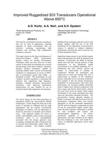
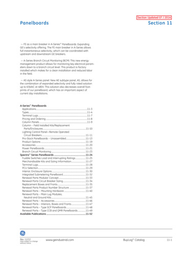
Section 3 – Performance Characteristics3.1. Dynamic Range3.1.1. DefinitionDynamic range is the measured values over which a transducer is intended to measure, specified byupper and lower limits. The lower limit, when dynamically (ac) coupled, is a few microvolts of noisegenerated by the silicon gauges and other internal components. When measuring statically (dccoupled), the lower limit will be determined by the zero measurand output and the long term, very lowfrequency thermal zero drift.3.1.2. RangeThe range of the pressure transducer specifies the recommended maximum peak pressure level foroptimum linear response. Most Kulite pressure transducers maintain good linearity up to 3 times therange, and specifications are provided for extended range. This is intended as a safety margin, not fornormal use.3.1.3. OverrangeAbove the range, nonlinearity increases, but the transducer continues to operate. As a single-degreeof-freedom system the mechanical response of the diaphragm to an applied pressure is frequencydependent. Do not apply full scale pressure at frequencies above 30% of resonance frequency. Thismay excite the diaphragm resonance and, cause erroneous data or lead to diaphragm failure. Apressure "snubber," in the form of a small orifice, may be used to attenuate high frequencies andpressure spikes.Figure 3-1: Instrument System Operating Range3.2. SensitivityThe sensitivity of a transducer is defined as the ratio of its electrical output to its mechanical input. Inthe case of piezoresistive pressure transducers, it is expressed as voltage per unit of pressure at therated excitation. Units of millivolts per psi (mV /psi) are used because Kulite pressure transducers arecalibrated and recommended for operation at a specified and fixed excitation voltage of 10.00 volts dc.3.2.1. Sensitivity CalibrationEach Kulite transducer is provided with a sensitivity calibration as measured by a readout device witha high input impedance (loading effects are discussed later). The transducer is operated at rated123 Semiconductor Products, Inc.Page 3-1
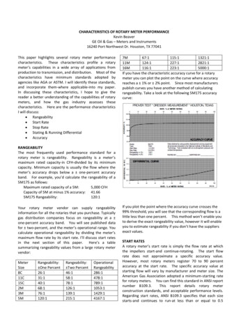
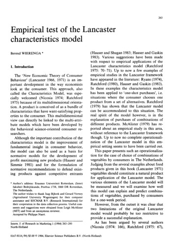
electrical excitation. The sensitivity is expressed in mV /psi and is numerically equal to root meansquare (rms) mV per rms psi and peak mV per peak psi3.2.2. PolarityFor many measurements, it is necessary to know the polarity of the system output signal relative to thedirection of pressure on the transducer. To determine this, the polarity of the transducer output and theinput-output phase relationship of the amplifier must be known.Unless otherwise specified, all Kulite pressure transducers produce a positive output signal when thepressure increases. Polarity of the excitation voltage must be applied in accordance with thespecifications on individual transducer data sheets. Kulite maintains standard strain gage practice withcolour codes of red for positive excitation, black for negative excitation, green for positive outputsignal, and white for negative output signal.3.3 Nonlinearity, Hysteresis & Nonrepeatability3.3.1 Definitions3.3.1.1 LinearityNon-linearity (sometimes called linearity) is defined as the maximum deviation of the calibrationcurve (output vs. input) from a specified straight line, expressed as a percent of full scale output, andmeasured on increasing measurand only.3.3.1.2. HysteresisHysteresis is defined as the maximum difference between output readings for the same measurandvalue, one point obtained while increasing from zero and the other while decreasing from full scale.The points are taken, on the same continuous cycle. The deviation is expressed as a percent of fullscale.3.3.1.3. Non-repeatabilityNon-repeatability (sometimes called repeatability) is defined as the ability of a transducer to reproduceoutput readings when the same measurand value is applied to it consecutively, under the sameconditions, and in the same direction. It is expressed as the maximum difference between outputreadings as a percent of full scale.3.3.2. Non-linearityAlthough a piezoresistive transducer is theoretically linear down to zero pressure, a practical lowerlimit is imposed by its noise level. As in all electrical conductors, the thermally-induced randommotions of free electrons cause noise; in addition, the current flow through the diffused gage elementscauses some additional noise having the characteristics of Schottky, or shot, noise. As a result, bothFigure 3-2: Input to Output CurvePage 3-2123 Semiconductor Products, Inc.
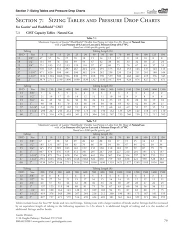
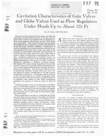
the diffused and SOI pressure transducers have a wide band noise characteristic of about 5 microvoltsRMS, measured at 20 C. This corresponds to about 1 x 10⁻⁴ psi for a 2 psi full scale transducer.Because this noise level is very small, the lower limit of dynamic range is usually a function of thenoise characteristics of the signal conditioning and power supply equipment used with the transducer.Single crystal silicon is a very good spring material, having essentially no plastic zone to its stressstrain curve and very low hysteresis. Because the input pressure to these transducers is supported onlyby the silicon element, these transducers become highly non-linear before burst is reached. Althougheach transducer is identified with a particular full scale range, there is no absolute end to the scale(with the exception of burst). One may elect to use a transducer at some pressure above full scale, orwell below full scale, depending on the requirements of the application. Each transducer is tested priorto shipment to a maximum limit for combined linearity and hysteresis to the "defined" full scale level,and for operation to a specified overrange level, typically 2 times full scale.The linearity plotted below and which is shown on the specifications for the transducers is the"independent linearity". This is defined as the maximum difference between the calibration point andthe linear regression line (least squares fit) drawn through the points for increasing measurand, zero to full scale. Numerically, this is usually about one-half the value when using an end-point, or terminalbased, linearity definition.Figure 3-3: Independent Linearity Curve3.3.3. HysteresisBecause of the excellent elastic characteristics of silicon, the hysteresis of these gages is usually verysmall, most of the time under 0.1% of full scale, and often as low as 0.03%. As such, the specificationshave simply been stated by indicating typical values for linearity and hysteresis, and then indicating amaximum limit for the two combined.Figure 3-4: Transducer Hysteresis123 Semiconductor Products, Inc.Page 3-3
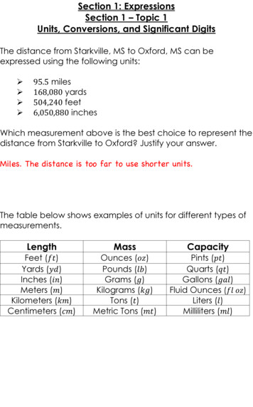
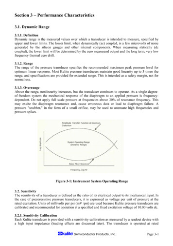
3.3.4. Non- repeatabilityNon-repeatability (sometimes repeatability) is the ability of a transducer to repeat output readingswhen the same pressure is applied to it consecutively under the same conditions, and in the samedirection as shown below. It is expressed as the maximum difference between output readings as apercent of full scale output (%FSO). Two calibration cycles are used to determine non-repeatability.Figure 3-5: Transducer Non-repeatability3.3.5. Combining Nonlinearity, Hysteresis, and Non- repeatabilityCombined nonlinearity, non-repeatability, and pressure hysteresis is the maximum RSS (root-sumsquare) average of the three independent parameters discussed above. This is the “total error band"calculated as the RSS average of three independent measurements.3.4. Zero Measurand Output (ZMO)This characteristic is often called zero balance, zero offset, or zero pressure output. Zero MeasurandOutput is expressed in millivolts at the output of the transducer under room conditions with full ratedexcitation, but with no pressure applied to the transducer. For an absolute pressure transducer, thismeans the output when measuring an absolute vacuum.Although the resistance elements in the bridge of a transducer are closely matched and compensatedduring manufacture, slight differences in resistance will exist. The differences result in a small offsetor residual dc voltage at the output of the bridge. This residual voltage is called Zero MeasurandOutput. Circuitry within associated signal conditioning instruments typically provides compensationor adjustment of the electrical zero.3.4.1. Mounting EffectsZero offset can be increased by improper transducer mounting of ultra miniature pressure transducers.Any stresses placed on or near the diaphragm will result in changes in the zero offset. However in thecase of Kulite threaded transducers, over-tightening has no effect on the zero measurand output andwill usually result in physical damage to the threads or the transducer body. Threaded devices have arecommended installation torque specified on the calibration sheet.3.4.2. Warm-upWarm-up time is the period of time, from application of excitation voltage, required to assure that thetransducer will perform within all specified tolerances. The zero offset will move to its final valuewhile the pressure transducer is being "warmed up." Kulite’s unique diaphragm design provides veryfast warm-up stabilisation. Kulite’s pressure transducers typically have warm-up times of onemillisecond or less to achieve less than 1 % deviation from long term performance. This characteristicenables the power supply to a pressure transducer to be turned on only for the duration of themeasurement which, for battery powered applications, is advantageous as it maximises battery life.3.4.3. Thermal StabilitySince both zero measurand output and sensitivity change with temperature, a stable temperatureenvironment assures the most stable measurements. However, Kulite’s design has been shown to haveonly very small output shifts even under severe conditions.Page 3-4123 Semiconductor Products, Inc.
When making dynamic measurements, the output of the pressure: transducer can be ac coupled to thesignal conditioner. This completely eliminates the zero offset, greatly reduces thermal zero shift, andprovides a controllable high pass filter. Of course, static or steady state measurements are no longerpossible.3.4.4. Effect of OverpressureKulite pressure transducers will survive overpressures of up to 2x full scale without any measurablechange in calibration. Burst pressure specifications are provided on the data sheets, and are discussedelsewhere in this text. Because the Kulite silicon diaphragms are very elastic until they fracture, if theyare not broken, it is unlikely that the transducer has been damaged.3.5. Phase ShiftThe transducers themselves are very lightly-damped dynamic systems with essentially no phase shift.Therefore, phase shift of the transducer is negligible. However, the damping characteristics of themeasured medium will affect the response of the diaphragm. Also, as discussed previously, connectingplumbing may have damping effects between the measurement point and the transducer, thus causingsome phase shift. Electrical characteristics of the transducer's integral compensation and balancingcomponents are all resistive, so they cause no phase shift. Typical signal conditioning will have either0 or 180 degree phase shift, depending on how many amplifier stages are included and theircharacteristics.3.6. Input and Output ResistanceThe primary uses of these specifications are to calculate excitation current requirements and to assurethat the bridge is not open or shorted.The input and output resistances of piezoresistive pressure transducers are specified on the individualdata sheets. For an equal-arm four-element Wheatstone bridge, the input and output impedances areequal and are in the order of 1,000 ohms. However, temperature compensating and zero balanceresistors are connected in series with the sensing elements. These additional resistors will usuallyresult in slightly differing input and output resistance. These full-bridge transducers have seriesresistors for thermal sensitivity compensation located external to the bridge, so that input resistance isapproximately 1.5 to 2 times the output value.For best results, the readout instrumentation input impedance should be at least 1 Megohm. For animpedance of 20 times the output impedance of the bridge, the sensitivity is reduced by 5%. With aninput impedance of 50 times, the reduction is 2% and an input impedance of 100 times yields a 1%reduction.Actual values of input and output impedance are recorded on each calibration sheet and are a verysimple and convenient means of verifying the health of any transducer.3.7. Thermal Sensitivity Shift and Zero ShiftThermal sensitivity shift and thermal zero shift define the effects on sensitivity and ZMO of operationat operating temperatures other than a normal ambient temperature 24 C. Thermal zero shift isspecified in terms of the maximum change of ZMO from its room temperature value, as a percent offull scale output.The operating and environmental temperature ranges for piezoresistive pressure transducers arespecified on individual data sheets. The operating range indicates the limits within which thetransducer will not be damaged. The compensated range indicates the limits within which thetransducer will operate with predictable characteristics or for which the transducer has beencompensated.123 Semiconductor Products, Inc.Page 3-5
Figure 3-8: Schematic of 4 Gauge Bridge Showing Resistors for Span & Zero ThermalCompensation3.7.1. Thermal Sensitivity ShiftSensitivity Shift - The temperature compensation utilised for standard production units typicallyreduces the thermal sensitivity shift to a maximum of 1% of output per 55 C change in operatingtemperature. Tighter specifications can be met, if required, and the compensated temperature rangecan be reduced, expanded and moved up or down. Calibration data can also be supplied at anyspecified temperature within the environmental range, even beyond the compensated range.Figure 3-6: Typical Thermal Sensitivity Shift3.7.2. Thermal Zero ShiftThe changes in resistance of the various elements caused by temperature changes is rarely balanced.Therefore, as temperature changes, th
Most Kulite pressure transducers maintain good linearity up to 3 times the range, and specifications are provided for extended range. This is intended as a safety margin, not for normal use. 3.1.3. Overrange Above the range, nonlinearity increases, but the transducer continues to operate. As a single-degree- of-freedom system the mechanical response of the diaphragm to an applied pressure is .