Transcription
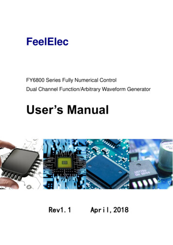
FeelElecFY6800 Series Fully Numerical ControlDual Channel Function/Arbitrary Waveform GeneratorUser’s ManualRev1.1April,2018
Guaranty and DeclarationCopyright 2017 FeelElec Technology Co. Ltd. All Rights Reserved.Declaration FeelElec reserves the right to modify or change parts of or all thespecifications and pricing policies at company’s sole decision. Information in this publication replaces all previously corresponding material. FeelElec shall not be liable for losses caused by either incidental orconsequential in connection with the furnishing, use or performance of thismanual as well as any information contained. Any part of this document is forbidden to be copied or photocopied orrearranged without prior written approval of FeelElec.Contact UsIf you have any problem or requirement when using our products or thismanual, please contact FeelElec.Tel: 0086 371 ec@126.com
ContentsGuaranty and Declaration . IProduct Introduction . 4Quick Start . 7General Inspection . 7Front Panel Overview . 8Back Panel Overview.11Power On and Inspection. 12User Interface . 13Appearance and Dimensions. 15Front Panel Operations . 16Waveform Output . 16Select Output Channel. 16Select Waveform . 17Set Frequency. 18Set Amplitude . 19Set Offset . 20Set Duty Cycle (Square). 21Set Phase . 22Enable Output . 23Example:Output Sine Waveform . 24Turn on burst function . 28Frequency Meter/Counter . 29Enable the Counter . 29Set the Counter. 30Sweep . 31Sweep Object . 31Sweep Start Position . 32Sweep End Position . 33Sweep Time. 34VCO (Voltage Control Output) Sweep . 34Sweep Type . 35Enable Sweep Function. 36System Configuration and Auxiliary Functions . 37Save and Load . 38Configuration . 39Uplink . 40Synchronization . 41Troubleshooting . 42Technical Specification . 43Appendix . 47
Product IntroductionThis manual applies to each model of FY6800series Function/ArbitraryWaveform Signal Generator. The last three characters of the model indicate theup limit output of Sine Wave (MHz). For example, the “60M” of the Model Number“FY6800-60M” indicates the Sine wave maximum output frequency is up to60MHz.FY6800series Dual-channel Function / Arbitrary waveform generator is a setof Function Signal Generator, Arbitrary Waveform Generator, Pulse Generator,Analog / Digital modulator, VCO, Sweep, Counters and Frequency Meter andother functions in a high Performance, cost-effective, multi-function signalgenerator. Abundant shortcut keys and graphical user interface simplifies everyoperation. Users do not have to spend a lot of time to learn and familiar with theoperation of the instrument, you can be skilled use. For education, research anddevelopment, production, testing, maintenance and other industries to provide anew choice.The instrument adopt the Direct Digital Synthesizer (DDS) technologyand provide stable, precise, pure and low distortion signals. Surface mountingtechnology improves interference immunity and operational life span. Can outputup to 97 groups of functions / arbitrary waveform, contains 33 groups of presetwaveforms and 64 groups of user-defined waveforms. Preset waveforms: Sine,Square (Duty Cycle adjustable), Pulse (Pulse width and cycle time can be setaccurately), Triangle/Ramp, CMOS(0 10V), Four channels TTL, ExponentialRise, Exponential Fall, Noise, ECG, DC etc.4FY6800 Series User’s Manual
Main Features: Adopt the Direct Digital Synthesizer (DDS) technology and provide stable,precise, pure and low distortion signals. Desktop design with ABS plastic housing, AC 100 - 240V (AC) wide voltagesupply; 2.4 inch TFT Color LCD with 320 240 resolution, displaying parameters andgraphics of the two channels at the same time. The instrument uses 14-bit high-speed D/A converter chip (5Vpp outputquantization error is less than 1mV), 250MSa/s sample rate, 14bits verticalresolution. Fully independent dual-channel output (equivalent to two independent signalsources), able to work synchronously, and the phase difference can beaccurately adjusted; Equipped with channel tracking function, when the tracking function is turnedon, all parameters of both channels can be updated according to the user'sconfiguration at the same time; Two or more instruments can synchronize multiple instruments through theSYNC port; Up to 98 sets of function/arbitrary waveforms can be output, including 34 setsof preset waveforms and 64 sets of user-defined waveforms. Presetwaveforms include: sine wave, square wave (duty ratio adjustable), trianglewave, pulse wave (preset pulse width and frequency can be precisely set),rise sawtooth wave, ramp sawtooth wave, staircase wave, trapezoidal pulsewave, Sink Pulse, narrow pulse, noise, exponential rise, exponential drop,electrocardiogram, Lorentz pulse, multiple audio waves, CMOS (0 10V),four-channel TTL level and DC voltage; Enable to store 64 arbitrary waveform data files, each one of waveformstorage depth 8192 points * 14bits; High frequency accuracy: Frequency accuracy can reach 10-6 orders ofmagnitude; The frequency resolution is relatively high: the full-range frequency resolutionis 1uHz (0.000001Hz); Amplitude resolution is higher: Amplitude resolution can be as low as 1mV(0.001V); With -10V 10V DC bias function ( 20MHz), resolution up to 1mV;FY6800 Series User’s Manual5
The duty cycle of both channels can be adjusted independently, with anaccuracy of 0.01%; The phase adjustment range of the two channels is 0 359.99 , and theadjustment accuracy is 0.01 ; No range limit: The full range of frequency is not divided into gear switches,program-controlled settings; With digital signal output function, it can realize any CMOS level with 0 10Vamplitude; Scanning function: It can scan the four properties of the signal: frequency,amplitude, offset, and duty cycle. It has two scanning modes: linear scan andlogarithmic scan. The scan time can reach 999.99S. The start and end of thescan can be set arbitrarily ; Burst Output Function: There has Manual Trigger, internal CH2 Trigger, andExternal Trigger for your options. It can output 1 1048575 pulse trains. VCO function: Support VCO voltage control signal output function (such asvoltage controlled oscillator). Various modulation types: AM, FM, PM, ASK, FSK and PSK modulations. 100M Frequency meter function: It can measure frequency, period, pulsewidth and duty cycle. Max. frequency workable is 100MHz and Min.frequency workable is 0.01 Hz. Counter Function: It has 2 coupling measure modes including DC couplingand AC coupling. This design can solve inaccuracy problem of AC coupling. All parameters can be calibrated by internal procedures; Equipped with powerful arbitrary waveform editing function, it can editarbitrary waveform on PC and download to instrument output waveform; Powerful communication features that can be controlled using a PC. Opencommunication protocol makes secondary development very simple; Standard dual full functional channels which are equivalent to twoindependent generators. High reliability: Large-scale integrated circuit, surface mount technology, highreliability, long service life; Output short-circuit protection: All signal outputs can work under loadshort-circuit conditions 60S or more; Can choose our FYA2000S series or FPA1000 series power amplifier tooutput 20W 100W signal in DC-10MHz width without any distortion.6FY6800 Series User’s Manual
Quick StartGeneral InspectionPlease follow the items below when you receive a new FY6800seriesFunction/Arbitrary Waveform Generator.1. Inspect the shipping container for damageKeep the damaged shipping container or cushioning material until thecontents of the shipment have been checked for completeness and theinstrument has passed both electrical and mechanical tests. The consigner orcarrier shall be liable for the damage to instrument resulting from shipment.2. Inspect the instrumentIn case of any damage, or defect, or failure, notify your FeelElec salesrepresentative.3. Check the accessoriesPlease check the accessories according to the Appendix C ( packing lists). Ifthe accessories are incomplete or damaged, please contact your FeelElec salesrepresentative.FY6800 Series User’s Manual7
Front Panel OverviewThe front panel is divided into several function areas for easy operation.Front PanelItemFunctionDescription1LCD2.4 inch TFT(320 240)color LCD. Operation instruction please checkchapter “User Interface”.2ManuButtonsManu buttons are matched with Manu displayed on the LCD. Presscorresponding button to activate submenu represented.Waveform selection button:— You can switch between sine, square wave, trianglewave, and any type of arbitrary wave.— Change the selected channel signal type.3FunctionButtons AreaTrigger and modulation function buttons— Can set a specific number of pulse train outputfunction(BURS)— Modulation mode can be set :ASK、FSK、PSK、AM、FM、PMSine, square, sawtooth and arbitrary waveforms can bescanned.— Supports scanning of four parameters of frequency,amplitude, offset, and duty cycle.Supports two linear and logarithmic scanning methods.Can switch to frequency meter and counter function,measure frequency, period, duty cycle, positive pulsewidth of external input signal— Supports DC and AC signal input.8FY6800 Series User’s Manual
— Supports 1 s, 10 s and 100 s gate time switching.— Dual channel output can work with frequency metermeasurement.VCO function can be set— Support VCO voltage control signal generator'sfrequency, amplitude, offset, duty cycle and otherparameter output functions (such asvoltage-controlled oscillator).Used to set auxiliary function parameters and systemparameters.— Supports storage of 20 sets of parameters such asfrequency, amplitude, offset, and phase— Support Chinese and English switching— Support tone off/on— Supports multi-machine cascading— Supports master/slave switchover in cascaded state— Supports dual-channel power-on default output statesettingPress Arrow buttons to select figure which you want to edit when settingvalues of each parameter.4Arrows5ADJ KnobWhen using the knob to set parameters, you can increase (clockwise)or decrease (counterclockwise) the value at the current cursor.6PowerButtonThe power indicator will remain on when it is turned on.When the signal generator is turned off, the indicator light will enter thebreathing lamp state and CH1 and CH2 will stop outputting (the output willremain at 0 volts).7CH1 channeloutputconnectorBNC connector, nominal output impedance 50Ω.When channel CH1 is on (the CH1 button indicator lights up), the connectoroutputs the waveform in the current configuration of CH1.8Channelcontrol, OKbuttonIt is used to control the output of the CH1 channel and can beswitched to the CH1 parameter setting interface in anyinterface.— Press this button, the CH1 light will turn on, and the CH1output will turn on. At this point, the [CH1] connector outputsthe signal in the current configuration.— Press this button again, the indicator light goes off, and atthis point, the CH1 output is turned off.Confirm button— When editing frequency parameters, press this key tochange the frequency unit.— When scanning the interface, press this button to start/stopscanning.FY6800 Series User’s Manual9
It is used to control the output of the CH1 channel and can beswitched to the CH1 parameter setting interface in anyinterface.—Press this button, the CH2 light will turn on, and the CH2output will turn on. At this point, the [CH2] connector outputsthe signal in the current configuration.— Press this button again, the indicator light goes off, and atthis point, the CH2 output is turned off.9CH2 channeloutputconnectorBNC connector, nominal output impedance 50Ω.When channel CH2 is on (the CH2 button indicator lights up), the connectoroutputs the waveform in the current configuration of CH2.10AC couplingmeasuringterminalBNC connector, input impedance 100Ω. For inputting signal of meter orcounter.10FY6800 Series User’s Manual
Back Panel OverviewThe back panel of FY6800is as picture 1-2 below. 4 BNC terminals on the leftare DC coupling measuring terminals Trig/FSK/ASK/PSK IN, external sweep inputVCO IN, Synchronization output connector SYNC OUT, and Synchronizationinput connector SYNC IN. Then follows TTL output terminal, USB terminal, powerswitch and power input socket.1. BNC connectorTrig/FSK/ASK/PSK IN: DC coupling measuring terminal and ASK/PSK/FSKmodulation trigger input terminal.VCO IN: External signal sweep input terminal can realize voltage controllingfrequency, voltage controlling amplitude, voltage controlling offset, voltagecontrolling duty cycle and so on. Frequency of external signal input should belower than 500 Hz.SYNC OUT: Synchronization signal output terminal.SYNC IN: Synchronization signal input terminal.2. TTL signal outputFrequency of Port A is same with frequency of CH1 output. Frequency of Port Bis same with frequency of Port A but with reverse phase (180 ). Frequency ofPort C is same with frequency of CH2. Frequency of Port D is same with Port Cbut with reverse phase (180 ).3. USB Device interfaceIt’s for communication with PC (This is a USB-TTL serial port and driver isneeded). Can programming by host computer.4.Power switch&Power input socket(voltage range AC100V-AC240V).WarningTo avoid instrument damage, voltage of signal input from EXT.INCANNOT exceed 20Vac dc.Voltage of signal input fromTrig/FSK/ASK/PSK IN CANNOT exceed DC5V.NoteTo ensure the normal work, please use 100-240V AC powersupply.FY6800 Series User’s Manual11
Power On and InspectionConnect to PowerPlease connect the generator to AC power supply using the Power cablesupplied in the accessories. The power supply use 100-240V AC power. Thepower of this instrument is less than 5W.Power OnTurn on the power switch after the power cord is connected. The generatorwill execute self-inspection. The LCD will show welcome interface after theinspection is over. If the generator cannot work normally, please check theChapter “Troubleshooting” for solution.Set the System LanguageFY6800series Function/Arbitrary Waveform Generator supports Chinese andEnglish system languages. You can press SYSTEM CONF to switch the systemlanguage.12FY6800 Series User’s Manual
User InterfaceThe user interface of FY6800provides four types of display modes: DualChannels Parameters (default), Single Channel Extension, Auxiliary Functionsand System Interface.Dual Channels Parameters (default)The upper half of LCD displays the channel selected currently and theparameters can be set. Press CH1 or CH2 to change current channel selected.1-4 User Interface (CH1 selected)Item12345DescriptionCurrent channel selected.Display current channel selected for operation.Current waveform selected.Display the name of current waveform selected. For example,“CH1 Sine” means current waveform selected of CH1 isSine Wave. It can be changed by press WAVE button.Meanwhile, waveform can be changed quickly by rotatingADJ Knob when waveform switch function is activated.Output status of current channel.Display On/Off status of current channel. It can be switchedby Press CH1 or CH2.WaveformDisplay diagram of current waveform(Including Arbitrary).Yellow indicates CH1 and blue indicates CH2.Manu BarDisplay current operable options .FY6800 Series User’s Manual13
6789101114FrequencyDisplay frequency value of current channel. Press FREQbutton to highlight it and use ADJ Knob and Arrows to changethe value.AmplitudeDisplay amplitude value of current channel. Press AMPLbutton to highlight it and use ADJ Knob and Arrows to changethe value.OffsetDisplay DC Offset value of current channel. Press OFFSbutton to highlight it and use ADJ Knob and Arrows to changethe value.Duty CycleDisplay Duty Cycle value of current channel. Press DUTYbutton to highlight it and use ADJ Knob and Arrows to changethe value.PhaseDisplay Phase value of current channel. Press PHAS tohighlight it and use ADJ Knob and Arrows to change thevalue.Parameters of the channel unselected.Display parameters of the channel unselected includingfrequency, amplitude, offset, phase, duty cycle and outputstatus. These Parameters cannot be changed directly in thisinterface. If you need to change them, Please switch thechannel to be selected.FY6800 Series User’s Manual
Appearance and DimensionsFY6800 Series User’s Manual15
Front Panel OperationsWaveform OutputFY6800series can output waveforms (Sine, Square, Triangle/Ramp, Pulseand Noise etc.) from one of the channels separately or from the two channels atthe same time. At start-up, the dual channels are configured to output a sinewaveform with 10kHz frequency and 5Vpp amplitude by default. Two channelsuse default setting saved at Position 1 when power on. Users can configure theinstrument to output various waveforms.Select Output ChannelCH1 and CH2 buttons are used to change current channel selected. Atstart-up, CH1 is displayed on the top with yellow color and CH2 is displayed onthe bottom with blue color. Press CH1 or CH2 to select channel needed. Whenselecting CH2 as output channel, CH2 parameters displays on the top forconfiguration.KEY POINT:CH1 and CH2 can not be selected at the same time. Users can first selectCH1 and then select CH2 after configuring the waveform and parameters ofCH1. If you need to change the parameters of two channel at same time,please refer to Chapter “Synchronization”.16FY6800 Series User’s Manual
Select WaveformFY6800 can output Function/Arbitrary Waveform including: Sine Inverse Exponent Square Positive Falling Exponent Triangle/Ramp Inverse Falling Exponent Rise Sawtooth Positive Logarithm Fall Sawtooth Inverse Logarithm Lorenz Pulse Positive Falling Logarithm Multitone Inverse Falling Logarithm Noise Linear FM Electrocardiogram (ECG) AM Trapezoidal Pulse FM Sinc Pulse Positive Half Wave Narrow Pulse Negative Half Wave Gauss White Noise Positive Half Wave Step Triangle Positive Step Inverse Step Positive ExponentRectification Negative Half WaveRectification User-defined waveformPress WAVE to change waveform selected. Or rotate ADJ Knob under waveformswitching status to change waveform. The waveform diagram displays on thescreen. Pressing the knob can change to arbitrary waveform directly whenchoosing waveform. At start-up Sine is selected by default. (Users can alsoconfigure start-up waveform. Please check Chapter “Save and Load”.WaveformsFunction NameFrequencyAmplitudeParameters OffsetPhaseDuty CycleSineSINE SquareSQUR TriangleTRGL SawtoothRamp ArbitraryArb Note: Arbitrary waveforms can be edited and downloaded from PC softwareprovided by FeelElec. The relevant software and driver can be downloaded fromour website: www.feelelec.com .FY6800 Series User’s Manual17
Set FrequencyFrequency is one of the most important parameters of waveforms. Fordifferent instrument models and waveforms, the setting ranges of frequency aredifferent. For detailed information, please refer to “Frequency” in“Specifications”. The default frequency is 10kHz.Press FREQ button to highlight value of Frequency. Then use Arrowbuttons and ADJ Knob to set the value. Press Arrows button to move the cursorand rotate ADJ Knob to set the value.Under setting frequency status, press ADJ Knob to change frequency unitsamong MHz, KHz, Hz, mHz, μHz.18FY6800 Series User’s Manual
Set AmplitudeThe amplitude setting range is limited by the “Attenuation” and “Frequency”settings. Please refer to “Output Characteristics” in “Specifications”. Thedefault value is 5Vpp.Press AMPL button to highlight amplitude value. Then use Arrows buttonand ADJ Knob to set the value. Press Arrows button to move the cursor androtate ADJ Knob to set the value.Key Points:1.What’s the difference of amplitude in Vpp and the corresponding value inVrms?Answer:Vpp is the unit for signal peak-peak value and Vrms is the unit for signal effective value.The default unit is Vpp.Note:For different waveforms, the relation between Vpp and Vrms is different. Therelation of the two units is as shown in the figure below (take sine waveform asan example).According to the figure above, the conversion relation between Vpp and Vrmsfulfills the following equation:Vpp 2 2 VrmsFor example, if the current amplitude is 5Vpp, For sine waveform, theconverted value is 1.768Vrms.FY6800 Series User’s Manual19
Set OffsetPress OFFS button to highlight offset value. Then use Arrows button andADJ Knob to set the value. Press Arrows button to move the cursor and rotateADJ Knob to set the value.The offset accuracy is 1mV. i.e. 0.001V.When frequency output is lower than 20MHz, the offset can be adjustedduring -10V 10V.When frequency output is higher than 20MHz, the offset can be adjustedduring -2.5V 2.5V.20FY6800 Series User’s Manual
Set Duty Cycle (Square)Duty cycle is defined as the percentage that the high level takes up in thewhole period (as shown in the figure below). This parameter is only availablewhen square is selected.The setting range of duty cycle is limited by the “FREQ” setting. Please referto “Waveform Characteristics” in “Specifications”. The default value is 50%.1. Press DUTY button to highlight duty cycle value. Then use Arrows button andADJ Knob to set the value. Press Arrows button to move the cursor and rotateADJ Knob to set the value. The setting range of duty cycle is 0.1%-99.9%;Press ADJ Knob under duty cycle setting status will initial the value to 50%.Set pulse wave pulse width ( ‘Adj-Pulse’ wave)Adjustable pulse wave refers to the square wave that can hold the fixed pulsewidth at any frequency, that is, the pulse width set by the user does not changewith the frequency.Pulse width setting method: in the adjustable pulse wave is selected, pressPULS button key to adjust the pulse wave pulse width time (Unit ns).The pulsewidth can be set by the arrow button and the knob. Use the arrow button to movethe cursor to select the bit you want to edit, and then turn the knob to modify thevalue. (Note: Do not set the length of the positive pulse width greater than orequal to the cycle time of the output waveform).FY6800 Series User’s Manual21
Set PhaseThe setting range of phase is from 0 to 359.9 . The phase resolution is 0.1 .The default phase value is 0 The start phase displayed on the screen is the default value or the phasepreviously set.Then press PHAS button to highlight phase value. Then use Arrows buttonand ADJ Knob to set the value. Press Arrows button to move the cursor androtate ADJ Knob to set the value.22FY6800 Series User’s Manual
Enable OutputAfter completing the parameter settings for the selected waveform, you need toturn on the channel to output the waveform. When the output is off, the LEDbelow the corresponding channel button is off; when the output is on, the LED ison.The default output of both CH1 and CH2 is enabled at power on, and the LEDsbelow the CH1 and CH2 buttons are lit.The default status can be modified. Press【SYS】button and then press【MORE】button to set the output status of dual channels.For CH1 there are two status:1) Generator is in parameter setting status and current channel selected isCH1, then press CH1 to switch between output ON/OFF.2) Generator is in other working status or current channel selected is notCH1, then press CH1 to make CH1 as channel selected and press CH1again to switch between output ON/OFF.For CH2 there are two status:3) Generator is in parameter setting status and current channel selected isCH2, then press CH2 to switch between output ON/OFF.4) Generator is in other working status or current channel selected is notCH2, then press CH2 to make CH2 as channel selected and press CH2again to switch between output ON/OFF.FY6800 Series User’s Manual23
Example:Output Sine WaveformThis section mainly introduces how to output a sine waveform (Frequency:20kHz, Amplitude:2.5Vpp, DC Offset: 1.6VDC, Start Phase: 90.9 ) from the [CH1]channel.1. Select output channelPress CH1 to select CH1. Now all characters and border of the channel isdisplayed in yellow.2. Select the SinePress WAVE button to select Sine. Then the diagram of Sine displays on thescreen.3. Set the frequencyPress FREQ button to highlight the frequency value. Press Arrow buttons tomove the cursor to the position “2” below. Then rotate the ADJ Knob to get “2”.FREQ:00’020.000’000’000kHz4. Set the AmplitudePress AMPL to highlight the amplitude value. Press Arrow buttons to movethe cursor and rotate the ADJ Knob to get the figures below.AMPL:02.500V5. Set OffsetPress OFFS to highlight the offset value. Press Arrow buttons to move thecursor and rotate the ADJ Knob to get the figures below.OFFS:01.600V6. Set PhasePress button to page down and press PHAS button to highlight phasevalue. Then Press Arrow buttons to move the cursor and rotate the ADJ Knob toget the figures below.PHAS:090.9 7. Enable the outputPress CH1 button to turn CH1 output on. The [CH1] connector outputs theconfigured waveform.8. Observe the output waveformConnect the [CH1] connector to the oscilloscope with BNC cable. Thewaveform is as shown below.24FY6800 Series User’s Manual
FY6800 Series User’s Manual25
Modulation FunctionPress the MOD button on the front panel to enable the modulation function. TheFY6800 can output the modulating waveform from the CH1 channel. This function usesthe waveform signal of CH1 as the carrier wave, the waveform signal of CH2, theexternal signal or the manual pulse signal as the modulation wave, and performs signalmodulation. It can realize FSK, ASK, PSK digital modulation, trigger pulse train output,and AM, FM, PM analog signal modulation function. The modulation signal is input bythe Trig/FSK/ASK/PSK IN at the end of the signal generator.Modulation parameter setting interface(Note: The signal generator will execute the current modulation funct
The front panel is divided into several function areas for easy operation. Front Panel Item Function Description 1 LCD 2.4 inch TFT(320 240)color LCD. Operation instruction please check chapter "User Interface". 2 Manu Buttons Manu buttons are matched with Manu displayed on the LCD. Press corresponding button to activate submenu .