Transcription
PrefaceT510 User ManualI
PrefaceT510 User ManualPrefaceFirstly thank you for purchasing our T510 series converters.This manual introduces how to use T510 series converter correctly. Before using (installation,operation, maintenance, inspection, etc.), please read this manual carefully. In addition, pleaseunderstand the safety precautions before using the product. In order to illustrate the details of the product, the illustrations in this specification are sometimes inthe state of removing the hood or safety cover. When using this product, please be sure to pack theshell or cover according to the regulations, and operate according to the contents of the instructions. The illustrations in this manual are for illustration only and may differ from the products youordered. Due to product upgrade or specification change, and in order to improve the convenience andaccuracy of the instructions, the contents of the instructions will be changed in time without furthernotice. If you need to order the instructions due to damage or loss, please contact our regional agents ordirectly contact our customer service center. If you still have some unknown problems in use, please contact our customer service center.MarkThe CE mark on the T510 declares that the frequency converter with the European lowvoltage directive (LVD) and EMC directive.The T510 series frequency converters complies with the following LVD and EMC directivesand standardsDirectiveDirective CodeEMC Directive2014/30/EULVD Directive2014/35/EUStandardEN61800-3:2004 A1:2012EN61800-5-1:2007 A1-2017EN61010-1:2010The T510 frequency converter complies with the requirements of standard IEC/EN 61800-3on the condition of correct installation and use by following the instruction in chapter 7I
ContentT510 User ManualContentChapter ISafety Information and Precautions in Use. .11.1 Security Matters.11.2 Points of Attentions. 3Chapter IIT510 Series Products Information. .72.1 Naming Rules.72.2 Nameplate.72.3 T510 Series Converter.82.4Basic Technical Specifications.92.5 Peripheral Electrical Components and System Composition. 112.6 Description of Appearance and Location Name of Converter . .152.7 Daily Maintenance and Service of Converter.182.8 Frequency Converter Warranty Description.192.9 Type Selection Guidance.202.10 Brake Component Selection Guide. 212.11 Selection of Resistance Value . 2112.12 Power Selection of Brake Resistance. .22Chapter III T510 Series Installation and Wiring of Converter.243.1 Mechanical Installation.243.2 Electrical Installation.28Chapter IV Operation and Display. 394.1 Introduction of Operation and Display Interface.394.2 Function Code Viewing and Modifying Method Description.414.3 Viewing Method of State Parameters. 424.4 Password Settings. 424.5 Self-learning of Motor Parameters . 42Chapter V Functional Parameters Table.445.1 Summary of Basic Functional Parameters . 443
ContentT510 User Manual5.2 Summary of Monitoring Parameters. 90Chapter VI Explanation of Parameters.93Unit F0Basic Function Group.93Unit F1First Motor Parameters. 113Unit F2 Vector Control Parameters .117Unit F3 V/F control parameters. 123Unit F4Digital Input and Output Terminals .130Unit F5 Analog Input and Output Groups. 146Unit F6Start-stop Control . 153Unit F7Keyboard and Display.158Unit F8 Auxiliary Function.163UnitF9 Closed-loop PID and Constant Pressure Water Supply Specific Parameters.170UnitFA Pendulum Frequency Multistage Instructions Simple PLC Function Parameters.180Unit FB Fault and Protection. 188Unit FC Fault Records.196Unit FDCommunication Parameters. 197Unit FE Customized Function Code.197Unit AOSecond Motor Control .198Unit L0 Monitoring Parameter Group. 198Chapter VII EMC (Electromagnetic Compatibility) .2047.1 Definitions.2047.2 EMC Standards Introductions.2047.3 EMC Guidance.204Chapter VIII Fault Diagnosis and Countermeasure . 2098.1 Fault Alarm and Countermeasure . 2098.2 Common Faults and Their Solutions.213Appendix A: T510 Serial Communication Protocol. .215Appendix B:One Drag Two Water Supply Card (T510WS6) Instructions.2304
Safety Information and PrecautionsT510 User ManualChapter I Safety Information and Cautions in UseSecurity Definition:In this manual, safety precautions fall into the following two categories:Danger: The danger caused by not operating as required may lead to serious injury oreven death. ;Warning: The danger of not operating as required may lead to serious injury or evendeath.When installing, debugging and repairing the system, please read this chapter carefully andoperate according to the safety precautions required in this chapter. In case of any injury orloss caused by irregular operation, it is irrelevant to our company.1.1 Security Matters1.1.1 Before installation:Danger Do not install the control system when it is found that there is water intake, parts aremissing or parts are damaged when unpacking the box When the packing list does not match the physical name, please do not install it!Danger Handling should be carried lightly, otherwise there is a risk of damage to equipment! Frequency converters with damaged drives or missing parts should not be used. The risk ofinjury! Do not touch the components of the control system with your hands, otherwise there is arisk of electrostatic damage!1.1.2 Installations:Danger Please install it on flame-retardant objects such as metals; stay away from combustibles.Otherwise, it may cause fire alarm! Do not unscrew the fixing bolts of equipment components at will, especially those withred marks!Warning Do not let lead head or screw fall into the driver. Otherwise, the driver will be damaged! Please install the driver in a place with less vibration and avoid direct sunlight. When two or more inverters are placed in the same cabinet, please pay attention to theinstallation position to ensure the heat dissipation effect.Danger1
Safety Information and PrecautionsT510 User Manual You must follow the instructions of this manual and be constructed by professionalelectrical engineers, otherwise unexpected dangers will arise. There must be a circuit breaker between the frequency converter and the power supply,otherwise fire may occur! Before wiring, please make sure that the power supply is in zero energy state, otherwisethere is the danger of electric shock! According to the standard, the inverter should be grounded correctly and normatively,otherwise there will be electric shock danger.1.1.3 Wiring:Danger You must follow the instructions of this manual and be constructed by professionalelectrical engineers, otherwise unexpected dangers will arise. Circuit breaker must be separated between frequency converter and power supply,otherwise fire alarm may occur. Before wiring, please make sure that the power supply is in zero energy state, otherwisethere is the danger of electric shock! According to the standard, the inverter should be grounded correctly and normatively,otherwise there will be electric shock danger.Danger The input power must not be connected to the output terminals (U, V, W) of the frequencyconverter. Pay attention to the marking of the terminal, do not connect the wrong line!Otherwise, the driver will be damaged! Ensure that the assigned lines meet the EMC requirements and the regional safetystandards. Refer to the manual for the wire diameters used. Otherwise, accidents may occur! The braking resistance must not be directly connected to the terminals of DC bus ( ), (-).Otherwise it will cause a fire alarm! Encoder must use shielding wire, and shielding layer must ensure single-ended reliablegrounding!1.1.4 Before power-on:Warning Make sure that the voltage level of the input power supply is the same as the rated voltagelevel of the frequency converter; whether the wiring positions of the input terminals (R, S, T)and the output terminals (U, V, W) are correct; and check whether there is short circuit in theperipheral circuit connected with the driver, and whether the connected lines are tight,otherwise causing driver damage! No voltage withstand test is required for any part of the frequency converter. The producthas been tested at the time of leaving the factory. Otherwise, it will cause accidents!Danger The converter must cover the cover before it can be powered on. Otherwise, it may causeelectric shock! All wiring of peripheral fittings must follow the instructions of this manual and connectcorrectly according to the method of circuit connection provided in this manual. Otherwise, itwill cause accidents!2
Safety Information and PrecautionsT510 User Manual1.1.5 After power-on:Danger Do not unclose the cover after power on. Otherwise, there is a danger of electric shock! Do not touch the driver and peripheral circuit with wet hands. Otherwise, there is a dangerof electric shock! Do not touch any input and output terminals of the converter. Otherwise, there is a dangerof electric shock! At the beginning of power-on, the frequency converter automatically detects the safety ofthe external high-voltage circuit. At this time, you must not touch the terminal of driver U, V,W or motor, otherwise there is a danger of electric shock!Danger If parameter identification is needed, please pay attention to the danger of injuring peoplein motor rotation. Otherwise, it may cause accidents! Do not change the parameters of the frequency converter manufacturer at will. Otherwise,it may cause damage to the equipment!1.1.6 In operation:Danger Do not touch the cooling fan and discharge resistance to test the temperature. Otherwise itmay cause burns! Non-professional technicians should not detect signals in operation. Otherwise, it maycause personal injury or equipment damage! During the operation of the frequency converter, something should be avoided falling intothe equipment. Otherwise, the equipment will be damaged! Do not use the method of contactor interruption to control the start and stop of the driver.Otherwise, the equipment will be damaged!1.1.7 Maintenance:Danger Do not electrify the equipment for repair and maintenance. Otherwise, there is a danger ofelectric shock! Make sure that the driver can be maintained and repaired only when the voltage ofconverter is lower than AC36V, whichever is two minutes after power failure. Otherwise,the residual charge on the capacitor will cause harm to people! Personnel without professional training should not repair and maintain the converter.Otherwise, it will cause personal injury or equipment damage! The parameters must be set after the frequency converter is replaced, and all plug-insmust be plugged in when power is cut off.1.2 Notes1.2.1 Insulation inspection of motor3
Safety Information and PrecautionsT510 User ManualMotor insulation inspection should be done before and during periodic inspection before thefirst use, long-term storage and reuse of the motor to prevent damage to the frequencyconverter due to insulation failure of the motor windings. When inspecting the insulation, it isnecessary to separate the motor connection from the frequency converter. It is suggested that500V voltage type megameter be used to ensure that the measured insulation resistance is notless than 5MΩ.1.2.2 Thermal protection of motorIf the rated capacity of motor and frequency converter does not match, especially when therated power of frequency converter is greater than the rated power of motor, it is necessary toadjust the parameters of motor protection in frequency converter or install thermal relay infront of motor to protect motor.1.2.3 Power frequency operationThe frequency converter can provide the output frequency of 0 Hz to 3200 Hz. If the customerneeds to run above 50 Hz, please consider the bearing capacity of the mechanical device.1.2.4 Vibration of mechanical devicesFrequency converter may encounter mechanical resonance point of load device in someoutput frequency band, which can be avoided by setting jump frequency parameters infrequency converter.1.2.5 Motor heating and noiseBecause the output voltage of the converter is PWM wave and contains certain harmonics, thetemperature rise, noise and vibration of the motor will increase slightly compared with thepower frequency operation.1.2.6 Capacitance with varistor or improved power factor on output sideThe output of the converter is PWM wave. If the output side is equipped with capacitors toimprove the power factor or varistors for lightning protection, it is easy to cause instantaneousovercurrent of the converter or even damage the converter. Please do not use it.1.2.7 Switching devices such as contactors for input and output of frequency converterIf a contactor is installed between the power supply and the input of the frequency converter,4
Safety Information and PrecautionsT510 User Manualit is not allowed to use the contactor to control the start and stop of the frequency converter. Itis necessary to use the contactor to control the starting and stopping time of the converter, andthe interval should not be less than one hour. Frequent charging and discharging can easilyreduce the service life of capacitors in frequency converters. If there are contactors and otherswitching devices between the output end and the motor, it should be ensured that theconverter operates on-off without output, otherwise the module in the converter will bedamaged easily.1.2.8 Use other than rated voltageIt is not suitable to use T series converter outside the allowable operating voltage rangestipulated in the manual, which can easily cause device damage in the converter. If necessary,please use the corresponding boost or step-down device for pressure change treatment.1.2.9 Three-phase input changed to two-phase inputThree-phase converter in T series can not be changed to two-phase use. Otherwise, it will leadto failure or damage of frequency converter.1.2.10 Lightning shock protectionThis series of converters are equipped with lightning overcurrent protection device, which hascertain self-protection ability for induction lightning. For where lightning occurs frequently ,customers should also install protection at the front end of the converter.1.2.11 Ambient temperature and quota reductionThe normal operating ambient temperature of this series of converters is –10 40 ,which needs to be degraded when the temperature exceeds 40 . The ambient temperature isreduced by 1.5% per litre, and the maximum operating temperature is 50 .1.2.12Altitude and derating in useIn the area with altitude over 1000 m, the heat dissipation effect of the converter becomesworse due to the thin air. The converter should be degraded in use. The derating of theconverter should be reduced by about 10% for every 1000 m elevation rise.1.2.13 Some special usagesIf customers need to use methods other than the recommended wiring diagram provided in5
Safety Information and PrecautionsT510 User Manualthis manual, such as common DC bus, etc., please consult our company.1.2.14 Attention to abandonment of frequency converterThe main circuit's electrolytic capacitor and PCB's electrolytic capacitor may explode whenburned. Toxic gases are produced when plastic parts are burned. Please treat it as industrialwaste.1.2.15 About adaptation motor1) The standard adapter motor is four pole squirrel cage induction motor. If it is not the motormentioned above, please select the frequency converter according to the rated current of themotor. If you need to drive permanent magnet synchronous motor, please consult ourcompany.2) The cooling fan of non-variable frequency motor is coaxially connected with the rotor shaft.When the speed decreases, the cooling effect of the fan decreases. Therefore, when the motoris overheated, the exhaust fan should be strengthened or replaced by variable frequencymotor.3) Frequency converter has built-in adapted motor with standard parameters. It is necessary toidentify motor parameters or modify default values according to the actual situation in orderto conform to the actual values as far as possible, otherwise it will affect the operation effectand protection performance4) Because of the short circuit inside the cable or motor, the frequency converter will give analarm, even the explosion machine. Therefore, the insulation short-circuit test of the initialinstalled motor and cable should be carried out first, and it should also be carried outfrequently in daily maintenance. Note that the frequency converter must be disconnected fromthe part under test when doing this test.6
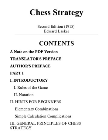
Product informationT510 User ManualChapter II T510 Series Products Information2.1 Naming RulesFigure 2-1 Naming Rules2.2 NameplateFigure 2-2 Nameplate7
Product informationT510 User Manual2.3 T510 Series InverterTable 2-1 T510 Inverter Model and Technical DataRatedCapacity(KVA)ModelRated InputCurrent(A)Single-phase power supply200 240VRated 5T510-2S2.2B4239.62.2Three-phase power supply380 T110G/132P160/192214/256210/253110/1328
Product informationT510 User Manual2.4 Basic Technical SpecificationsTable 2-2 Technical Specifications for Frequency ConvertersItemMaximumfrequencyCarrier frequencyInput frequencyresolutionControl modeStart-up torqueSpeed rangeBasicfunctionsSteady speedaccuracyTorque controlaccuracyOverloadcapacityAutomatic torqueliftingThree ways ofV/F curveTwo ways of V/FseparationRamp modeDC brakingJOG controlOn boardmultiple presetspeedsBuilt-in rque limitationand controlSafetyself-inspection ofpower-onSpecificationsVector control: 300.00HzV/F control: 3200Hz0.5kHz-16kHz, The carrier frequency can be adjustedautomatically based on the load features.Digital setting: 0.01HzAnalog setting: maximum frequency 0.025%Open-loop vector control (SVC)Closed-loop vector control (FVC)V/F ControlG type: 0.5Hz/150% (SVC), 0Hz/180% (FVC)P type: 0.5Hz/100%.1:100 (SVC)1:1000(FVC) 0.5%(SVC) 0.02%(FVC) 5%(FVC)G type: 150% rated current 60s; 180% rated current 3SP type: 120% rated current 60s; 150% rated current 3SManual torque lifting 0.1%-30.0%.Straight-line type;Multi-point type;N-power V/F curve (1.2 power, 1.4 power, 1.6power,1.8power, 2power ,square)Two types: complete separation and half separationStraight-line ramp or S-curve ramp, Four groups ofacceleration /deceleration time with the range of0.0s-6500.0s0.00Hz - maximum output frequency,Braking time: 0.0s - 36.0sBraking action current value: 0.0% - 100.0%.JOG frequency range: 0.00Hz-50.00Hz,JOG acceleration / deceleration time: 0.0s-6500.0sIt implements up to 16 speeds via the simple PLC functionor combination of DI terminal states.It realizes process-controlled closed-loop control systemeasily.It can keep constant output voltage automatically when themain voltage changes.It cam limit the torque automatically and preventfrequent over current tripping during the running process.It can realize the safety detection of peripheral equipmentsuch as grounding, short circuit and so on.9
Product e andover-loss speedcontrolFast current LimitCommon DC busfunctionQUICK keyMF.K keyTextile swingfrequency controlTiming controlRunningcommand nningchannelInput terminalOutput terminalDisplayandkeyboardLED displayKeyboard lockand functionselectionProtectionFunctionOptional peratureT510 User ManualAutomatic limit of current and voltage during operation toprevent frequent over-current and over-voltage trippingMinimizing overcurrent fault and protecting frequencyconverter in normal operationIt can realize common DC bus functions of multiplefrequency converters.User-defined shortcut menuProgrammable key: command channel switching/forwardand reverse running/JOG running function selectionGiven length control functionTiming control function: setting time range 0h-65535hThree channels: operation panel, control terminal andserial communication port .They can be switched overbetween these sources in various ways.There are total 10 of frequency sources, such as digitalsetting, analog voltage setting, analog current setting,pulsesetting and serial communication port setting. They can beswitched over these sources in various ways.10 kinds of auxiliary frequency instructions. It can realizeauxiliary frequency fine adjustment and frequencysynthesis flexibly.Seven digital Input terminals, of which X5 can be used ashigh-speed pulse input. Compatible with active PNPOr NPN input mode, two analog input terminals, can beused as voltage or current input.A high-speed pulse output terminal DO (optional opencollector type), 0 kHz-100 kHz square wave signal output,It can realize the output of set frequency, output frequencyand other physical quantities.Three digital output terminals and two relay outputterminalsTwo analog output terminals, 0/4mA-20mA or 0V-10V,can realize setting frequency and transmission.Output frequency and other physical quantitiesDisplay monitoring parameters, output frequency, setfrequency, bus voltage, etc.To realize partial or total lock of keys, define the scope ofaction of some keys, in order to prevent misoperation.Short circuit detection , input and output phase lossprotection, overcurrent protection, overvoltage protection,undervoltage protection , overheat protection and overloadprotectionBrake assemblyIndoor ,free from direct sunlight, dust-free, corrosivegases, combustible gases, oil smoke, vapour, drip or salt,etc. 1000m-10 C 40 C (ambient temperature is 40 C 50 C ,please derate to use)10
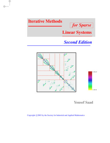
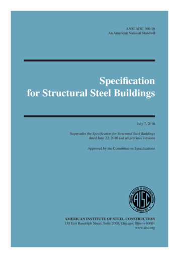
Product informationT510 User ManualHumidityLess than 95 k% RH, no water droplet condensationVibrationless than 5.9m/s 2 (0.6g)Storagetemperature-20 60 IP levelIP20Pollution gradePD2PowerdistributionsystemTN,TT2.5 Peripheral Electrical Components and System CompositionWhen using T510series converter to control asynchronous motor to constitute control system,it is necessary to install various electrical components on the input and output sides of theconverter to ensure the safety and stability of the system. In addition, the T510 series systemstructure is as follows:11
Product informationT510 User Manual12
Product informationT510 User Manual2.5.1 Instructions for the Use of Peripheral Electrical ComponentsTable 2-3 T510 Instructions for the Use of Peripheral Electrical Components of FrequencyConvertersFittings NameAir switchContactorInstallation LocationFunctional DescriptionFront end of input Cut off power supply when downstream equipment isloopovercurrent Frequent power-up and power-down operation (lessAir switch and inverterbetween input sides than twice per minute) or direct start-up operationshould be avoided through contactor.AC input reactorInverter input sideEMC input filterInverter input sideDC reactorbetween p and P Increase the input power factor; Effective elimination of high-order harmonics atinput side to prevent damage to other equipment dueto distortion of voltage waveform Elimination of input current imbalance caused byinterphase unbalance of power supply Reduce the external transmission and radiationinterference of the frequency converter. Reduce the conduction interference from the powersource to the converter, and improve theanti-interference ability of the converter. Increase the input power factor; Improve the efficiency and thermal stability of theconverter. It can effectively eliminate the influence ofhigh-order harmonics on the input side of theconverter and reduce the external conduction andradiation interference. Frequency converter output side generally containsmore higher harmonics. When the distance betweenthe motor and the frequency converter is relativelylong, there is a large distributed capacitance in thecircuit. One of the harmonics may produce resonanceInstall close to thein the circuit, which has two effects:converter between theAC output reactoroutput side of the a)Destroy the insulation performance of the motor,converter and the motor which will damage the motor for a long time.b) It produces large leakage current, which causesfrequent protection of frequency converter. Generally,the distance between frequency converter and motor isover 100 m. It is recommended to install output ACreactor.Notes: Do not install capacitors or surge suppressors on the output side of the converter, which will13
Product informationT510 User Manuallead to the failure of the converter or the damage of capacitors and surge suppressors. The input/output (main loop) of the converter contains harmonic components, which mayinterfere with the communication equipment attached to the converter. Therefore,anti-interference filter is installed to minimize interference. Detailed information and selection of peripheral equipment refer to the selection manual ofperipheral equipment.2.5.2 Selected AccessoriesIf you need the following accessories, please specify when ordering.Table 2-4 T510 Inverter Selected AccessoriesNameModelFunctionsNoteThe built-in brake units ofsingle-phase 0.4kw 2.2kwBuilt-in Product model and three-phasebraking unitwith "B" 0.75kw 18.5kw G typeengines are standardconfiguration.Selection ofbui
T510-2S0.75B 1.5 8.2 4 0.75 T510-2S1.5B 3 14 7 1.5 T510-2S2.2B 4 23 9.6 2.2 Three-phasepowersupply 380 480V 50/60Hz T510-4T0.75G/1.5PB 1.5/3 3.4/5 2.1/3.8 0.75/1.5 T510-4T1.5G/2.2PB 3/4 5/5.8 3.8/5.1 1.5/2.2 T510-4T2.2G/3.0PB 4/4.9 5.8/8.0 5.1/6.8 2.2/3.0 T510-4T3.0G/4.0PB 4.9/5.9 8.0/10.5 6.8/9.0 3.0/4.0 T510-4T4.0G/5.5PB 5.9/8.9 10.5/14.6 9 .