Transcription
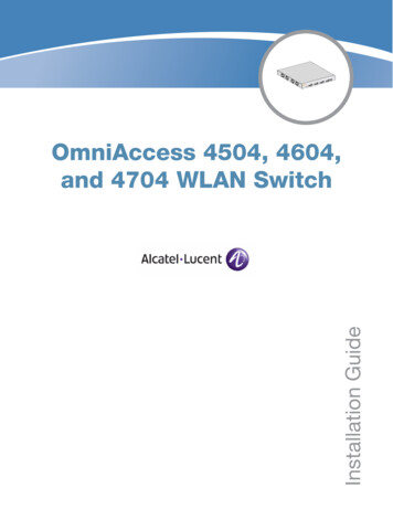
Installation GuideOmniAccess 4504, 4604,and 4704 WLAN Switch
Copyright 2007 Alcatel-Lucent. All rights reserved.Specifications in this manual are subject to change without notice.Originated in the USA.TrademarksAOS-W, Alcatel 4308, Alcatel 4324, Alcatel 6000, Alcatel 41, Alcatel 60/61/65, Alcatel 70, and Alcatel 80 are trademarks of AlcatelLucent in the United States and certain other countries.Any other trademarks appearing in this manual are the property of their respective companies.Legal NoticeThe use of Alcatel-Lucent switching platforms and software, by all individuals or corporations, to terminate Cisco or Nortel VPN clientdevices constitutes complete acceptance of liability by that individual or corporation for this action and indemnifies, in full, AlcatelLucent from any and all legal actions that might be taken against it with respect to infringement of copyright on behalf of Cisco Systemsor Nortel Networks."www.alcatel-lucent.com26801 West Agoura RoadCalabasas, CA 91301OmniAccess 4504, 4604, and 4704 WLAN Switch Installation Guide0510353-01 December 2007
ContentsPrefaceChapter 1Chapter 2Appendix AGuide Overview5Related Documents5Contacting Alcatel-Lucent5Hardware Overview7About the OmniAccess 4504, 4604, and 47047Minimum Software Requirements8Package Checklist8Hardware Model OverviewFront View1000Base-X (SFP) Ports10/100/1000Base-T Gigabit Ethernet PortsSerial Console PortRear ViewAC Power Socket8999101111LED Status tion RequirementsPhysical InstallationRack MountingTabletop DeploymentInitial Setup and Network Connectivity131313131515Removal15Specifications, Safety & Compliance17Physical SpecificationsPower Management SpecificationsPower ConsumptionPower Specifications (AC Input Requirements)Operating SpecificationsStorage Specifications171717171718Safety and Regulatory ComplianceFCC Class A Device1818Proper Disposal of Alcatel-Lucent EquipmentWaste of Electrical and Electronic EquipmentEuropean Union RoHSChina RoHS18181919OmniAccess 4504, 4604, and 4704 WLAN Switch Installation GuideContents 3
4 ContentsOmniAccess 4504, 4604, and 4704 WLAN Switch Installation Guide
PrefaceThis preface includes the following information:zAn overview of the contents of this manualzA list of related documentation for further readingzAlcatel-Lucent support and service informationGuide OverviewzChapter 1, “Hardware Overview” on page 7 provides a detailed hardware overview of the threeOmniAccess WLAN Switches covered in this guide: the OAW-4504, the OAW-4604, and the OAW4704.zChapter 2, “Installation” on page 13 provides rack mounting and installation instructions.zAppendix A, “Specifications, Safety & Compliance” on page 17 includes product technicalspecifications and safety and regulatory compliance information.Related DocumentsThe following documents are referred to in this guide and are considered components of the completedocumentation set needed for successful installation and management of an OmniAccess WLANSwitch:zAOS-W Quick Start GuidezAOS-W User GuidezOmniVista Mobility Manager User GuideContacting Alcatel-LucentWeb Site SupportMain priseSupport Sitehttps://service.esd.alcatel-lucent.comSupport Emailsupport@ind.alcatel.comTelephone SupportNorth America1-800-995-2696Latin America1-877-919-9526Europe 33 (0) 38 855 6929Asia Pacific 65 6240 8484Worldwide1-818-878-4507OmniAccess 4504, 4604, and 4704 WLAN Switch Installation GuidePreface 5
6 PrefaceOmniAccess 4504, 4604, and 4704 WLAN Switch Installation Guide
Chapter 1Hardware OverviewAbout the OmniAccess 4504, 4604, and 4704The OmniAccess 4504, 4604, and 4704 are enterprise-class, wireless LAN switches. These switchesconnect, control, and intelligently integrate wireless Access Points (APs) and Air Monitors (AMs) into awired LAN system.Available base models:zOmniAccess 4504 (OAW-4504)The OAW-4504 is capable of supporting up to 32 campus connected APs. The following base modelsare available and can be upgraded by purchasing optional software licenses:z OAW-4504-0: no built-in AP support; optional Alcatel-Lucent AP upgrade licenses available. OAW-4504-8: includes built-in campus connected AP support of up to 8 APs; additional AlcatelLucent AP upgrade licenses available.OmniAccess 4604 (OAW-4604)The OAW-4604 is capable of supporting up to 64 campus connected APs. The following base modelsare available and can be upgraded by purchasing optional software licenses:z OAW-4604-0: no built-in AP support; optional Alcatel-Lucent AP upgrade licenses available. OAW-4604-32: includes built-in campus connected AP support of up to 32 APs; additional AlcatelLucent AP upgrade licenses available.OmniAccess 4704 (OAW-4704)The OAW-4704 is capable of supporting up to 128 campus connected APs. The following basemodels are available and can be upgraded by purchasing optional software licenses:NOTE OAW-4704-0: no built-in AP support; optional Alcatel-Lucent AP upgrade licenses available. OAW-4704-64: includes built-in campus connected AP support of up to 64 APs; additional AlcatelLucent AP upgrade licenses available.Feature related AP licenses are counted independently and in addition to the Alcatel-Lucent APupgrade licenses. Contact your Alcatel-Lucent sales representative for complete details regardingsoftware licensing options and support capacity.OmniAccess 4504, 4604, and 4704 WLAN Switch Installation GuideHardware Overview 7
Minimum Software RequirementsThe OmniAccess 4504, 4604, and 4704 require AOS-W 3.2.0 or later.AOS-W software builds prior to version 3.2.0 do not support the OmniAccess 4504, 4604, and 4704. Ifyour network currently runs on a software build prior to 3.2.0, you must upgrade the software on yourmaster and local switches to 3.2.0 or later prior to installing an OmniAccess 4504, 4604, or 4704 WLANSwitch in your existing network.The master switch, its redundant master switch, and all of its local switches must run on the samecode of AOS-W. Once you upgrade your network and install an OmniAccess 4504, 4604, or 4704WLAN Switch into your network, verify that the software version on your switch matches the rest ofthe network. If the code shipped on the switch is prior to the version that you upgraded yournetwork to, you must upgrade the code on the switch to match the rest of the network.NOTEPackage ChecklistzOmniAccess 4504, 4604, or 4704 WLAN SwitchzAC Power Cord (country-specific)zRack Mount Brackets with Hardware (for rack mounting)zFlat Serial Cable (RJ-45)zRubber Feet (for table top deployments)zSerial Console Port Adaptor (RJ-45 to DB9)zAOS-W Software Documentation CDzAOS-W Quick Start GuidezEnd User License Agreement (EULA)NOTEInform your supplier if there are any incorrect, missing, or damaged parts. If possible, retain thecarton, including the original packing materials. Use these materials to repack and return the unit tothe supplier if needed.NOTEOptional accessories, such as SFP modules, are available for use with an OmniAccess 4504, 4604,or 4704 and are sold separately. Contact your Alcatel-Lucent sales representative for details andassistance.Hardware Model OverviewNOTE8 Hardware OverviewThe physical hardware overview covers all three switches: the OmniAccess 4504, 4604, and 4704 .The difference between the three switch models is dependent on the licensing level purchased,which is covered in About the OmniAccess 4504, 4604, and 4704 on page 7. The switch modeldepicted in the illustrations throughout this section is the OAW-4504.OmniAccess 4504, 4604, and 4704 WLAN Switch Installation Guide
Front ViewFigure 1 OmniAccess 4504, 4604, and 4704 Front ViewDual-media ports (4x); 1000Base-Xor 10/100/1000Base-TSerial Console Port1000Base-X (SFP)PortsNOTE10/100/1000-Base-TGigabit Ethernet PortPorts zero through three are dual-media ports and can utilize either the 1000Base-X or 10/100/1000Base-T connections provided. However, the 1000Base-X fiber connection has priority over the10/100/1000Base-T copper connection. If a link is detected for the 1000Base-X interface, the 10/100/1000Base-T connection will be disabled.1000Base-X (SFP) PortsThere are four 1000Base-X combination ports for fiber connectivity only and are intended for use withAlcatel-Lucent SFPs (mini-GBICs).To purchase compatible SFP modules, contact your Alcatel-Lucent sales representative for details andassistance.NOTEAlcatel-Lucent tests and supports Alcatel-Lucent optics within their switch systems. Third partyoptics are not tested or supported; therefore, Alcatel-Lucent does not guarantee proper functionalityof third party optics when used in an Alcatel-Lucent system.10/100/1000Base-T Gigabit Ethernet PortsThere are four 10/100/1000Base-T Gigabit Ethernet (RJ-45) ports. Gigabit Ethernet uses all eight wiresand each pair is used in a bi-directional fashion, meaning the same pairs are used for both datatransmission and reception. Figure 2 illustrates the CAT-5 pin-out found on an RJ-45 connector. TheCAT-5 pin-out pairs the following pins on a 10/100/1000Base-T Gigabit Ethernet port: 1/2, 3/6, 4/5, and 7/8.OmniAccess 4504, 4604, and 4704 WLAN Switch Installation GuideHardware Overview 9
Figure 2 Gigabit Ethernet Port Pin-Out1000Base-T GigabitEthernet PortRJ-45 FemalePin-Out12345678Signal NameFunctionBI DA BI DABI DB BI DC BI DCBI DBBI DD BI DD-Bi-directional pair ABi-directional pair -ABi-directional pair BBi-directional pair CBi-directional pair -CBi-directional pair -BBi-directional pair DBi-directional pair -DSerial Console PortA serial console port is provided for connection to a terminal, allowing for direct local management.The port’s RJ-45 female connector accepts an RS-232 serial cable with a male connector.Figure 3 Serial Console Port Pin-OutSerialConsole PortRJ-45 RxDCommunication settings for the serial console port are indicated in Table 1.Table 1 Console Terminal Settings!Baud RateData BitsParityStop BitsFlow Control96008None1NoneDo not connect an Access Point (AP) to the serial console port. The serial console port is compatiblewith only RS-232 devices. Non-RS-232 devices, such as APs, are not supported.CAUTIONSerial Console Port AdaptorA modular adaptor can be used to convert the RJ-45 (female) connector to a DB9 (male) connector.Refer to Figure 4 for complete details.Figure 4 RJ-45 (female) to DB9 (male) Modular Adaptor ConversionRJ-45 10 Hardware OverviewInternalConnectionsRJ-45TxD345GNDRxD6DB-9 putOutputOmniAccess 4504, 4604, and 4704 WLAN Switch Installation Guide
Rear ViewFigure 5 OmniAccess 4504, 4604, and 4704 Rear ViewAC Power SocketAC Power SocketThe OmniAccess 4504, 4604, and 4704 support integrated AC powering and the AC power socket on therear of the unit is for use with an AC power cord (country-specific). Refer to Power ManagementSpecifications on page 17 for power specification details.LED Status IndicatorsTable 2 OmniAccess 4504, 4604, and 4704 LED Status IndicatorsLEDFunctionIndicatorStatusPOWERInput Power StatusIndicatorOn (Solid Green)Power onOffNo powerSTATUSLNK1000Base-X PortsACT1000Base-X portsLNK/ACT10/100/1000Base-T PortsModule Status Indicator On (Solid Green)Link Status IndicatorActivity Status IndicatorLink/Activity StatusIndicatorOmniAccess 4504, 4604, and 4704 WLAN Switch Installation GuideDevice is operationalOn (Solid Red)Device failedOn (Solid Amber)Device is loadingsoftwareOffNo powerOn (Solid Green)Link has beenestablishedOffNo link on portOn (Blinking Green)Port is transmitting orreceiving dataOffNo activityOn (Solid Green)Link has beenestablishedOn (Blinking Green)Port is transmitting orreceiving dataHardware Overview 11
Table 2 OmniAccess 4504, 4604, and 4704 LED Status IndicatorsLED100010/100/1000Base-T Ports12 Hardware OverviewFunctionInterface SpeedIndicatorIndicatorStatusOffNo link on portOn (Solid Green)1000 Mbps interfacespeed in useOff10/100 Mbpsinterface speed in useOmniAccess 4504, 4604, and 4704 WLAN Switch Installation Guide
Chapter 2InstallationInstallationPre-Installation RequirementsThe following tools and equipment are required for installation of an OmniAccess 4504, 4604, or 4704:zRack Mount Bracket (2x)z6-32 x 1/4” Phillips Flat Head Screws (6x, included with rack mount brackets)z12-24 x 5/8” Phillips Flat Head Screws (4x, 19-inch (48.26 cm) rack system mount screws)zSuitable Screwdrivers for both screw typeszAC power cord (country-specific)Physical InstallationRack MountingTo install an OmniAccess 4504, 4604, or 4704 switch into a 19-inch (48.26 cm) rack system:1. Place a rack mount bracket over the mounting holes on one side of the switch (see Figure 1).2. Secure the bracket to the switch using three 6-32 x 1/4” phillips flat head screws and a suitablescrewdriver (see Figure 1).3. Repeat these steps on the opposite side of the switch.Figure 1 Rack Mount BracketsSwitchRack Mount Bracket (2x)6-32 x 1/4” Phillips Flat Head Screws(6x, 3x per bracket)OmniAccess 4504, 4604, and 4704 WLAN Switch Installation GuideInstallation 13
4. Mount the switch within your organization’s rack system using four 12-24 x 5/8” phillips flat headscrews and a suitable screwdriver (see Figure 2).Figure 2 Rack Mount InstallationStandard 19-inchRack SystemSwitch with Rack MountBrackets12-24 x 5/8”Phillips Flat Head Screws(4x, 2x per bracket)5. Leave a minimum of four inches (10 cm) of space on the left and right side of the unit for proper airflow and ventilation (see Figure 3).6. Leave additional space in the front and back of the unit to access power cords, network cables, andLED status indicators (see Figure 3).Figure 3 Air Flow RequirementsKeep Open forEasy AccessKeep Clear forAir Intake4 inches (10 cm)MinimumKeep Clear forAir ExhaustKeep Open forEasy Access7. Connect the AC power cord (country-specific) to the rear of
OmniAccess 4504, 4604, and 4704 WLAN Switch Installation Guide Preface 5 Preface This preface includes the following information: zAn overview of the contents of this manual zA list of related documentation for further reading zAlcatel-Lucent support and service information Guide Overview zChapter 1, “Hardware Overview” on page 7 provides a detailed hardware overview of the three


