Transcription
A Review of AviationNavigation Systems from old W. J. Overholser's barn to NextGen andMetroplexBy Gerald A. Silver*Van Nuys Airport Citizens Advisory CouncilJanuary 2017Ver 1.0
Summary of this presentation This presentation describes various aircraft navigationsystems ranging from simple onboard visualnavigation, called Pilotage, through to sophisticatedSatellite Systems. PART 1 describes Dead Reckoning, Radio Navigation,Electronic Navigation including GPS and Inertialsystems. PART 2 describes the FAA’s newest NextGen andMetroplex systems under consideration and noiserelated issues.
PART 1 Dead Reckoning, Radio Navigation,Electronic Navigation including GPSand Inertial systems
Types of Navigation SystemsPilotageDead ReckoningRadio NavigationADFVOR/DME/RNAVElectronic NavigationLoranInertialGPSCelestial
Aviation navigation dates back tothe early 1900’sPilots flying from point A to point B usedrecognizable landmarks such as buildings, lakes,rivers, mountain tops and the like. Pilotage was avisual process of calculating one's position bytraveling from one recognizable landmark toanother. It did not use astronomical observationsor electronic navigation methods.
Pilotage Flying from Point A to Point B
Dead Reckoning In navigation, dead reckoning is theprocess of calculating one's currentposition by using a previouslydetermined position, or fix, andadvancing that position based uponknown or estimated speeds overelapsed time and course.
Area Navigation (RNAV) Generic name for a system thatpermits point-to-point flight Onboard computer that computes aposition, track, and groundspeed VOR/DME Loran Inertial GPS
Automatic direction finder ADF ADF equipment determines the direction orbearing relative to the aircraft by using acombination of directional and nondirectional antennae to sense the directionin which the combined signal is strongest. This display looks like a compass card witha needle superimposed, except that thecard is fixed with the 0 degree positioncorresponding to the center line of theaircraft.
Radio Navigation - VORsVHF Omni Directional Radio Range VORs derived from the old 4-course radiorange from the late 1920’s and 1930’s Gained widespread use for navigation inthe 1950’s. Made instrument navigationcommonplace. Remain the basis for mostof the world’s air navigation systemsand will be for 5-10 yrs.
VOR Flying from Point A to Point B
VHF Omni Directional Radio Range (VOR)
Photograph VOR antenna
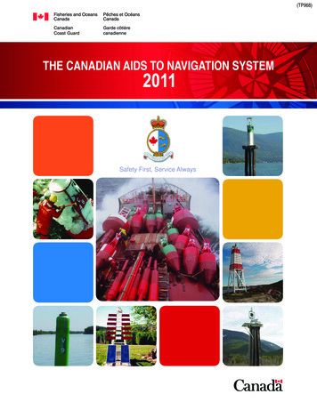
The principle of the VOR – Radials360MagneticNorth045315135º090270135225180
Principles of operation VORs broadcast 360 separate radialsemanating from the station in alldirections. VORs broadcast 2 signals- thereference (or 360-N) signal and therotating signal.
Inertial Navigation System Self-contained source of: Position, groundspeed, & heading Does not need a receiver Cannot be jammed Applies calibration correction after eachflight
Global Positioning System GPS System of 24 satellites, 4/5 of which are inview at all times Receiver uses 4 of these to determineposition of aircraft Each satellite transmits code which containssatellite position and GPS time Receiver, knowing how fast signal was sentand at what time, calculates position
System of 24 satellites, 4/5 are inview at all times
PART 2 The FAA’s newest NextGen andMetroplex systems and noise relatedissues.
INTRODUCING NEXTGEN The purpose is to improve airspace efficiency andreduce complexity Focus on major metropolitan areas Optimize flight paths and climb/descent profiles Institute collaborative teams to broadly proliferateexisting PBN* experience and expertise Promote RNAV “everywhere” and RNP (RequiredNavigational Performance) “where beneficial” Integrate airspace and procedure design Decouple operations arriving and departing adjacentairports *Performance Based Navigation is area navigation or RNAV. RNAV is amethod of navigation which permits aircraft operation on any desired flightpath within coverage of station-referenced navigation aids
Primary and secondary airports withinmulti-airport systems in the United States
Six NextGen Programs Reshaping operations in the NationalAirspace System (NAS):1. Automatic Dependent Surveillance–Broadcast(ADS-B)2. Data Communications (Data Comm)3. En Route Automation Modernization (ERAM)4. Terminal Automation Modernization andReplacement (TAMR)5. NAS Voice System (NVS)6. System Wide Information Management(SWIM)
1. Automatic DependentSurveillance–Broadcast Automatic Dependent Surveillance–Broadcast (ADS-B) is the successor to radarthat uses onboard avionics to broadcast anaircraft’s position, altitude and velocity to anetwork of ground stations, which relays theinformation to air traffic control displays andto nearby aircraft equipped to receive thedata via ADS-B In. ADS-B In provides operators of properlyequipped aircraft with traffic positioninformation delivered directly to the cockpit.Aircraft equipped with a Universal AccessTransceiver (UAT) will also receive weatherand Notices to Airmen (NOTAM) via theFlight Information Services–Broadcast (FISB) service.
2. Data Communications Data Communications (Data Comm) enablescontrollers and pilots to communicate withdigitally delivered messages, rather than relysolely on radio voice communications. With thepush of a button, controllers can electronicallysend routine instructions, such as departureclearances and weather avoiding reroutes,directly to the flight deck. Messages appear only on the cockpit display ofthe aircraft to which they apply, reducing thepotential for miscommunication that can occurfrom radio voice exchanges.
3. En Route AutomationModernization En Route Automation Modernization (ERAM) is one ofthe foundational programs of NextGen. It is a morecapable and flexible platform than the decades-oldHOST legacy system it replaces. ERAM is now onlineat the 20 en route traffic control centers in thecontiguous United States. It performs core functions at the FAA centers wherehigh-altitude air traffic is controlled. ERAM processesflight and surveillance radar data, enables efficientcontroller-pilot communications and generatesdetailed display data to air traffic controllers.
4. Terminal AutomationModernization and Replacement The Terminal Automation Modernization andReplacement (TAMR) program upgrades multiple airtraffic control technologies to a single, state-of-theart platform: the Standard Terminal AutomationReplacement System (STARS). STARS is afoundational NextGen technology that enablesAutomatic Dependent Surveillance–Broadcast(ADS-B) and other NextGen programs. Controllers use STARS to provide air traffic controlservices to pilots in terminal airspace — theairspace immediately surrounding major airports.
5. National Airspace System (NAS)Voice System (NVS) The National Airspace System (NAS) Voice System (NVS)will replace decades-old analog technology with secure,digital Voice over Intranet Protocol (VoIP) technology.Current point-to-point voice-switching technology allowscontrollers to speak to aircraft within range of theirnearby radio site. By contrast, NVS works over a secure FAA digitalnetwork and is not limited by geography. With the flip ofa switch, NVS will allow voice traffic to move from onelocation to another, anywhere in the country. Infrastructure (FTI) network. FTI’s multi-layered securityprevents unwanted access to the system while alsoproviding a NAS-wide connection for voice systems.
6. System Wide InformationManagement System Wide Information Management (SWIM) is thedigital data-sharing backbone of NextGen. SWIMinfrastructure enables air traffic management-relatedinformation sharing among diverse, qualified systems. The platform offers a single point of access for aviationdata, with producers of data publishing once and usersaccessing the information they need through a singleconnection. It enables increased common situational awarenessthroughout the National Airspace System (NAS) andimproves the FAA’s ability to securely deliver the rightinformation to the right people at the right time.
FAA’s NextGen Implementation PlanOur focus is on integration and executionAirport Development OEP Airports OEP Metro AreasAir Traffic Operations Initiate Trajectory-based Operations Increase Arrivals and Departuresat High Density Airports Increase Flexibility in the TerminalEnvironment Improve Collaborative Air TrafficManagement Reduce Weather Impact Improve Safety, Security andEnvironmental Performance Transform FacilitiesAircraft & Operator Requirements AvionicsImplementing NextGenFederal AviationAdministration2929
INTRODUCING METROPLEX Main purpose of Metroplex is toenhance efficiency in the SoCalMetroplex Reduce Complexity Provide Predictability Provide Flexibility
Southern California Metroplex Metroplex is an optimized approach to integratedairspace and procedures projects. Airspace andprocedures solutions are limited to those that canbe achieved without producing significant noiseincreases Noise impacts assessed and reported in anEnvironmental Assessment (EA) Draft EA will include a noise analysis andtrack/altitude information Years modeled: 2015 and 2020 forecastconditions Preliminary analysis shows no significant noiseincreases in the 65 DNL
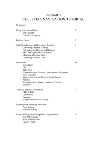
SoCal Metroplex Area of InterestThis figure shows the six primary airports including BUR, LAX, LGB,ONT, SAN and SNA along with CRQ, PSP, SMO and VNY
Crowded SoCal Airspace
SoCal Metroplex Airports The Southern California Metroplex consists ofairspace delegated to the SCT and ZLAInteractive operations at eight SCT airports wereexamined closely Los Angeles International Airport (LAX)San Diego International Airport (SAN)Bob Hope Airport (BUR)Ontario International Airport (ONT)John Wayne Airport – Orange County (SNA)Long Beach/Daugherty Field (LGB)Santa Monica Municipal Airport (SMO)Van Nuys Airport (VNY)
Example Arrival and Departureproceedures under consideration SID: Standard Instrument Departure STAR: Standard Terminal ArrivalRoute
SoCal Metroplex SIDs and STARs
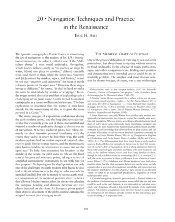
Interpreting the graphics LIGHT BLUE LINES are actual flight track, how the aircraft are flyingunder current procedures.DARK BLUE LINES (small jet) are the TARGETS fly abilityline. Meaning this is how we expect the aircraft (small jets) to fly theprocedure.LIGHT GREEN LINES (medium jets) are the TARGETS fly ability line.Meaning this is how we expect the aircraft (medium jets) to fly theprocedure.PURPLE LINES (small turboprops) are the TARGETS fly ability line.Meaning this is how we expect the aircraft (small turboprops) to fly theprocedure.ORANGE LINES (large turboprops) are the TARGETS fly ability line.Meaning this is how we expect the aircraft (large turboprops) to fly theprocedure.WHITE LINES are the TARGETS proposed design lines. They are areference for design only.BLACK LINES are the current TARGETS design lines. Again utilizedfor reference only
BUR OROSZ SID
BUR OROSZ STAR
Metroplex brings new noise issuesA “Metroplex” is a geographic area covering severalairports serving major metropolitan areas, such as theLos Angeles Basin. The project involves changing aircraft flight pathsand/or altitudes in certain areas. The new flight procedures, using satellite-basednavigation technology, are more precise and create anarrower flight path, resulting in a concentration offlights over certain areas. Residents in areas under the concentrated flight pathmay experience more noise, while those outside theflight path may experience less noise.
Culver City noise issues Culver City to Sue Over Flight Path ChangesAt its October 24, 2016 Council meeting, the City Council ofthe City of Culver City directed the City Attorney to file alawsuit against the Federal Aviation Administration (FAA)related to aircraft overflights. The FAA recently issued anEnvironmental Assessment of its So Cal Metroplex changingflight path procedures.Over the past several years, hundreds of Culver City residentshave come to City Council meetings, and over a thousandcomplaints were submitted to the FAA and LAX, regardingserious concerns about current noise and pollution impacts ofthe aircraft overflights. Recently, 300 residents signed apetition submitted to the City Council, requesting that theCouncil take legal action against the FAA to protect themagainst further impacts from the So Cal Metroplex project. Culver City in the News - 10/26/2016
Orange County noise issues Orange County criticizes flight changes Orange County has filed a petition in federal court to join NewportBeach in suing the Federal Aviation Administration with both trying toblock revised air traffic plans for planes coming in and out of JohnWayne Airport. The legal motion, filed Nov. 10, argued that the changescould lead to a significant increase in airplane noise for areassurrounding the county-owned-and-operated airport. The county’s Board of Supervisors filed the petition in the U.S. 9thCircuit Court of Appeals after a vote to join with the coastal city “inprotecting all of our communities,” said Supervisor Todd Spitzer. “Wehave an absolute duty to speak up for citizens who will be affected byairport noise, and Newport Beach has been so aggressive in doing that.We as a county need to be right alongside it,” said Spitzer, whorepresents Tustin and other areas of Orange County heavily affected bythe arrival of jets.The legal action targets an environmental impactreview conducted by the FAA to determine the effects of the SouthernCalifornia Metroplex project, which would replace outdated, groundbased air-traffic control procedures with a GPS-based system at 21regional airports, including John Wayne.Los Angeles Times 11/24/2016
Phoenix noise issues PHOENIX -- Phoenix residents disrupted for monthsby noise from new flight paths at Phoenix Sky HarborInternatio
ORANGE LINES (large turboprops) are the TARGETS fly ability line. Meaning this is how we expect the aircraft (large turboprops) to fly the procedure. WHITE LINES are the TARGETS proposed design lines. They are a reference for design only. BLACK LINES are the current TARGETS design lines