Transcription
U.S. DEPARTMENT OFENERGYEnergy Efficiency &Renewable EnergyADVANCED MANUFACTURING OFFICEImprovingCompressed AirSystem PerformanceA Sourcebook for IndustryThird EditionIMPROVING COMPRESSED AIR SYSTEM PERFORMANCE: A SOURCEBOOK FOR INDUSTRY
U.S. Department of EnergyEnergy Efficiency and Renewable EnergyBringing you a prosperous future where energy is clean,abundant, reliable, and affordableACKNOWLEDGEMENTSImproving Compressed Air System Performance: A Sourcebook for Industry is a cooperative effort of the U.S.Department of Energy’s Office of Energy Efficiency and Renewable Energy (EERE) Advanced Manufacturing Officeand the Compressed Air Challenge . EERE originally undertook this project as part of a series of sourcebookpublications on industrial systems. Other topics in this series include: pump systems; fan systems; motors; processheating; and steam systems. As work on the first edition progressed, the Compressed Air Challenge was formed,bringing together the extraordinary combined talents of compressed air system auditors, trade associations,equipment manufacturers and distributors, utilities, and government agencies in a collaborative effort to improvethe performance of industrial compressed air systems. The two programs joined forces in preparing the second andthis third edition. For more information about EERE and the Compressed Air Challenge , see Section 3: Where toFind Help.The Compressed Air Challenge , EERE’s Advanced Manufacturing Office, Lawrence Berkeley National Laboratory, andResource Dynamics Corporation wish to thank the staff at the many organizations who so generously assisted in thecollection of data for this sourcebook. The contributions of the following participants are appreciated:Ron Marshall, Manitoba HydroWilliam Scales, Scales Industrial Technologies, Inc.Gary Shafer, Shafer Consulting Services, Inc.Paul Shaw, Scales Industrial Technologies, Inc.Paul Sheaffer, Lawrence Berkeley National LabRick Stasyshan, Compressed Air and Gas InstituteH.P. Van Ormer, Air Power USAThe review and comment from the following participants is also appreciated: Niff Ambrosino, Scales IndustrialTechnologies, Inc.; Joseph Ghislain, Ford Motor Company; Thomas Hyde, Alcoa, Inc.; Tracey Kohler, CompressedAir Challenge; Doug Peace, Shaw Industries Group, Inc.; David Prator, Atlas Copco; Tom Osborn, BonnevillePower Administration; Bill Orthwein, U.S. Department of Energy, Dean Smith, Air Science Engineering, Inc.;Dusty Smith, Pneu-Logic Corp.; Jody Sutter, Ingersoll Rand; Tony Yanessa, Tennessee Valley Authority; JeffYarnall, Rogers Machinery Co.Finally, a special thanks to William Scales for his extraordinary assistance in developing this third edition and previouseditions.Prepared for:Compressed Air Challenge and theUnited States Department of EnergyPrepared by:Lawrence Berkeley National LaboratoryBerkeley, CAResource Dynamics CorporationMcLean, VAIMPROVING COMPRESSED AIR SYSTEM PERFORMANCE: A SOURCEBOOK FOR INDUSTRY
CONTENTSQUICK START GUIDESECTION 1. INTRODUCTION TO INDUSTRIAL COMPRESSED AIR SYSTEMSSECTION 2. PERFORMANCE IMPROVEMENT OPPORTUNITY ROADMAPFACT SHEET 1: ANALYZING COMPRESSED AIR NEEDS . 20FACT SHEET 2: POTENTIALLY INAPPROPRIATE USES OF COMPRESSED AIR . 24FACT SHEET 3: COMPRESSED AIR SYSTEM LEAKS . 28FACT SHEET 4: PRESSURE DROP AND CONTROLLING SYSTEM PRESSURE . 31FACT SHEET 5: COMPRESSED AIR SYSTEM CONTROLS . 34FACT SHEET 6: COMPRESSED AIR STORAGE . 43FACT SHEET 7: PROVEN OPPORTUNITIES AT THE COMPONENT LEVEL . 45FACT SHEET 8: MAINTENANCE OF COMPRESSED AIR SYSTEMS FOR PEAK PERFORMANCE . 51FACT SHEET 9: HEAT RECOVERY AND COMPRESSED AIR SYSTEMS. 58FACT SHEET 10: BASELINING COMPRESSED AIR SYSTEMS . 60FACT SHEET 11: DETERMINING YOUR COMPRESSED AIR SYSTEM ANALYSIS NEEDS . 62FACT SHEET 12: COMPRESSED AIR SYSTEM ECONOMICS AND SELLING PROJECTS TO MANAGEMENT. 65SECTION 3. WHERE TO FIND HELPADVANCED MANUFACTURING OFFICE . 70THE COMPRESSED AIR CHALLENGE. 71DIRECTORY OF CONTACTS . 73RESOURCES AND TOOLS . 74BOOKS AND REPORTS . 74EDUCATIONAL BROCHURES. 77ONLINE RESOURCES . 78DOE TIP SHEETS . 79DOE CASE STUDIES . 79PERIODICALS. 79SOFTWARE . 79VIDEOS . 80WORKSHOPS AND TRAINING COURSES. 80APPENDIX A: GLOSSARY OF BASIC COMPRESSED AIR SYSTEM TERMINOLOGY . 83APPENDIX B: PACKAGED COMPRESSOR EFFICIENCY RATINGS . 89APPENDIX C: CAGI COMPRESSOR AND DRYER DATA SHEETS . 91ROTARY COMPRESSOR. 92REFRIGERANT DRYERS . 93ROTARY VARIABLE FREQUENCY DRIVE COMPRESSOR . 94CENTRIFUGAL COMPRESSORS. 95IMPROVING COMPRESSED AIR SYSTEM PERFORMANCE: A SOURCEBOOK FOR INDUSTRY
APPENDIX D: THE COMPRESSED AIR SYSTEM MARKETPLACE . 96MARKET SIZE AND ENERGY CONSUMPTION . 96COMPRESSED AIR SYSTEM MARKETPLACE . 96THE MARKET FOR COMPRESSED AIR SYSTEM EFFICIENCY SERVICES . 100APPENDIX E: GUIDELINES FOR SELECTING A COMPRESSED AIR SYSTEM PROVIDER. 103WHAT TO LOOK FOR WHEN SELECTING A SERVICE PROVIDER . 103COMPRESSED AIR CHALLENGE . 104LEVELS OF ANALYSIS OF COMPRESSED AIR SYSTEMS. 104LEVELS OF ANALYSIS . 105IMPROVING COMPRESSED AIR SYSTEM PERFORMANCE: A SOURCEBOOK FOR INDUSTRY
FIGURESFigure 1.1 Components of a Typical Industrial Compressed Air System .4Figure 1.2 Compressor Family Tree 6Figure 2.1 Performance Opportunities . 19Figure 2.2 Simplified Compressed Air System Block Diagram . 22Figure 2.3 Pressure Profile at Single Point in Time 22Figure 2.4 Pressure Profile over a Defined Time Period . 23Figure 2.5 Effect of Receiver Capacity on Lubricant-Injected, Rotary Compressor with Load/Unload Capacity Control 40Figure 2.6 Lubricant-Injected Compressor with Inlet Valve Modulation . .41Figure 2.7 Lubricant-Injected Rotary Compressor Performance with Variable Displacement . 41Figure 2.8 Lubricant-Injected Rotary Compressor Performance with Variable Speed Control . 42Figure D-1. The Compressed Air System Marketplace . 97TABLESTable 1.1 Industrial Sector Uses of Compressed Air 16Table 1.2 Non-Manufacturing Sector Uses of Compressed Air 17IMPROVING COMPRESSED AIR SYSTEM PERFORMANCE: A SOURCEBOOK FOR INDUSTRY
QUICK START GUIDEThis sourcebook is designed to provide compressed airsystem users with a reference that outlines opportunities forsystem performance improvements. It is not intended tobe a comprehensive technical text on improvingcompressed air systems, but rather a document that makescompressed air system users aware of the performanceimprovement potential, details some of the significantopportunities, and directs users to additional sources ofassistance. The sourcebook is divided into the three mainsections outlined below.Section 1. Introduction to IndustrialCompressed Air SystemsThis section is intended for readers who want to gain anunderstanding of the basics of industrial compressed airsystems. The components of an industrial compressed airsystem are described and applications of compressed airsystems in different industries are characterized.Compressed air system users already familiar withcompressed air fundamentals may want to skip this section.Section 2. Performance ImprovementOpportunity RoadmapThis section consists of a series of fact sheets thatoutline specific opportunities for enhancing theperformance of a compressed air system. The factsheets address system-level opportunities such as usingheat recovery and fixing leaks as well as individualcomponent-level opportunities. The following factsheets are included.2.1—Analyzing Compressed Air Needs2.2—Potentially Inappropriate Uses of Compressed Air2.3—Compressed Air System Leaks2.4—Pressure Drop and Controlling System Pressure2.5—Compressed Air System Controls2.6—Compressed Air Storage2.7—Proven Opportunities at the Component Level2.8—Maintenance of Compressed Air Systems for PeakPerformance2.9—Heat Recovery and Compressed Air Systems2.10—Baselining Compressed Air Systems2.11—Compressed Air System Assessments and Audits andSelecting a Service Provider2.12—Compressed Air System Economics and SellingProjects to ManagementSection 3. Where to Find HelpThe third section of this sourcebook is a directory ofresources, tools, and information that are available tocompressed air systems users to help them improvetheir systems. It includes: A description of EERE’s Advanced ManufacturingOffice, a division of the U.S. Department of Energyaimed at improving the performance of industrialsystems A description of the Compressed Air Challenge , anational effort involving all compressed air marketstakeholders aimed at increasing the demand for highperformance compressed air systems, primarilythrough awareness building, education, and training A directory of association and other organizationcontacts involved in the compressed air systemmarket A listing and description of compressed air systemrelated resources and tools, including books,brochures, periodicals, software, videos, workshops,and training courses. Electric utility companies may be able to providesome assistance or referrals Financial assistance may be available from utilityrebates, energy efficiency grants and loans. A listingof available assistance by state is available atwww.dsireusa.org.AppendicesThe sourcebook also contains five appendices:A. A glossary defining terms used in thecompressed air industryB. Information on the Compressed Air and GasInstitute’s (CAGI) Packaged CompressorEfficiency RatingsC. Data sheets outlining a common format andstyle for reporting compressor and dryerperformanceD. Overview of the compressed air systemsmarketplaceIMPROVING COMPRESSED AIR SYSTEM PERFORMANCE: A SOURCEBOOK FOR INDUSTRY 1
QUICK START GUIDEE. Guidelines for Selecting a Compressed AirSystem Service Provider, a document that offersguidance for selecting a firm to provideintegrated services to improve compressed airsystem performance.The Systems ApproachImproving and maintaining peak compressed air systemperformance requires not only addressing individualcomponents, but also analyzing both the supply anddemand sides of the system and how they interact. Thispractice is often referred to as taking a “systemsapproach” because the focus is shifted away fromindividual components to total system performance.Applying the systems approach usually involves thefollowing types of interrelated actions: Establishing current conditions and operatingparameters, including baselining of inefficiencies Determining present and future processproduction needs Gathering and analyzing operating data anddeveloping load duty cycles Assessing alternative system designs andimprovements Determining the most technically andeconomically sound options, taking intoconsideration all of the sub-systems Implementing those options Assessing operations and energy consumptionand analyzing economics Continuing to monitor and optimize the system Continuing to operate and maintain the systemfor peak performance.IMPROVING COMPRESSED AIR SYSTEM PERFORMANCE: A SOURCEBOOK FOR INDUSTRY 2
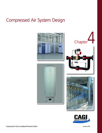
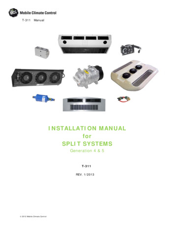
SECTION 1: INTRODUCTION TO COMPRESSED AIR SYSTEMSThis section of the sourcebook is intended for readerswho want to gain an understanding of the basics ofindustrial compressed air systems. A glossary of basicterminology is included in Appendix A for usersunfamiliar with the terms used in this chapter.Compressed air is widely used throughoutmanufacturing industries and is often considered the“fourth utility” at many facilities. Almost everyindustrial plant, from a small machine shop to animmense pulp and paper mill, has some type ofcompressed air system. In many cases, the compressedair system is so vital that the facility cannot operatewithout it. Plant air compressor systems can vary in sizefrom a small unit of 5 horsepower (hp) to huge systemswith more than 50,000 hp.In many industrial facilities, air compressors use moreelectricity than any other type of equipment.Inefficiencies in compressed air systems can besignificant. Energy savings from system improvementscan be substantial, resulting in thousands, or evenhundreds of thousands of dollars of potential annualsavings, depending on use. A properly managedcompressed air system can save energy, reducemaintenance, decrease downtime, increase productionthroughput, and improve product qualityCompressed air systems consist of a supply side and ademand side. The supply side includes compressors andair treatment (dryers and filters). The demand sideincludes distribution and end-use equipment. Aproperly managed supply side will result in clean,appropriately dried, stable air being delivered at theappropriate pressure in a dependable, cost-effectivemanner. A properly managed demand side minimizeswasted air and uses compressed air for appropriateapplications. Improving and maintaining peakcompressed air system performance requiresaddressing both the supply and demand sides of thesystem and how the two interact.Components of an IndustrialCompressed Air SystemA compressor is a machine that is used to increase thepressure of a gas. The earliest compressors werebellows, used by blacksmiths to intensify the heat intheir furnaces. The first industrial compressors weresimple, reciprocating piston-driven machines poweredby a water wheel.A modern industrial compressed air system is composedof several major sub-systems. Major sub-systemsinclude the compressor, prime mover, controls,treatment equipment and accessories, and thedistribution system. The compressor is the mechanicaldevice that takes in ambient air and increases itspressure. The prime mover powers the compressor.Controls serve to regulate the amount of compressedair being produced. The treatment equipment removescontaminants from the compressed air, and accessorieskeep the system operating properly. Distributionsystems are analogous to wiring in the electricalworld—they transport compressed air to where it isneeded. Compressed air storage can also serve toimprove system performance and efficiency. Figure 1.1shows a representative industrial compressed airsystem and its components.Compressor TypesMany modern industrial air compressors are sold“packaged” with the compressor, drive motor, andmany of the accessories mounted on a frame for ease ofinstallation. Provision for movement by forklift iscommon. Larger packages may require the use of anoverhead crane. An enclosure may be included forsound attenuation and aesthetics.IMPROVING COMPRESSED AIR SYSTEM PERFORMANCE: A SOURCEBOOK FOR INDUSTRY 3
INTRODUCTION TO COMPRESSED AIR SYSTEMSCompressorPackageEnclosureDryerAir InletFilterAir nd LubricantCoolerMotorControlPanelCompressorAir EndLubricant/AirSeparatorCondensateDrainFilter, RegulatorLubricatorFigure 1.1 Components of a Typical Industrial Compressed Air SystemIMPROVING COMPRESSED AIR SYSTEM PERFORMANCE: A SOURCEBOOK FOR INDUSTRY 4
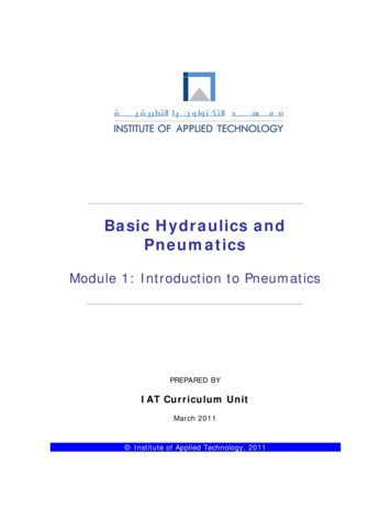
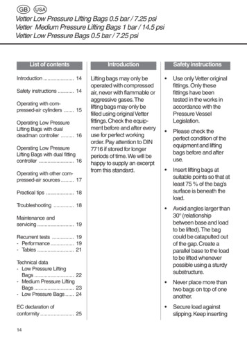
INTRODUCTION TO COMPRESSED AIR SYSTEMSAs shown in Figure 1.2, there are two basic compressortypes: positive-displacement and dynamic. In thepositive-displacement type, a given quantity of air orgas is trapped in a compression chamber and thevolume which it occupies is mechanically reduced,causing a corresponding rise in pressure prior todischarge. At constant speed, the air flow remainsessentially constant with variations in dischargepressure. Dynamic compressors impart velocity energyto continuously flowing air or gas by means of impellersrotating at very high speeds. The velocity energy ischanged into pressure energy both by the impellers andthe discharge volutes or diffusers. In the centrifugaltype dynamic compressors, the shape of the impellerblades determines the relationship between air flowand the pressure (or head) generated.Positive Displacement CompressorsThese compressors are available in two types:reciprocating and rotary. Reciprocating compressorswork like bicycle pumps with the exception that anelectric motor replaces the human energy source. Apiston, driven through a crankshaft and connecting rodby an electric motor, reduces the volume in the cylinderoccupied by the air or gas, compressing it to a higherpressure. Single- acting compressors have acompression stroke in only one direction, while doubleacting units provide a compression stroke as the pistonmoves in each direction. Large, industrial reciprocatingair compressors are double-acting and water-cooled.Multi-stage, double- acting compressors are the mostefficient compressors available, and are typically larger,noisier, and more costly than comparable rotary units.Reciprocating compressors are available in sizes fromless than 1 hp to more than 600 hp.Rotary compressors have gained popularity and arenow the “workhorse” of American industry. They aremost commonly used in sizes from about 10 to 500 hp.The most common type of rotary compressor is thehelical-twin, screw-type (also known as rotary screw orhelical-lobe). Male and female rotors mesh, trappingair, and reducing the volume of the air along the rotorsto the air discharge point. Rotary screw compressorshave low initial cost, compact size, low weight, and areeasy to maintain. Rotary screw compressors may be airor water-cooled. Less common rotary compressorsinclude sliding-vane, liquid-ring, and scroll-type.Single-Acting, Reciprocating Air CompressorsThis type of compressor is characterized by its“automotive” type piston driven through a connectingrod from the crankshaft. Compression takes place onthe top side of the piston on each revolution of thecrankshaft. Single-acting, reciprocating air compressorsare generally air-cooled. These may be single- stage,usually rated at discharge pressures from 25 to 125pounds per square inch gauge (psig), or two-stage,usually rated at discharge pressures from 125 psig to175 psig or higher.The most common air compressor in the fractional andsingle-digit hp sizes is the air-cooled, reciprocating aircompressor. Single-acting reciprocating compressorsabove 30 hp are much less common. Two-stage andmulti-stage designs include inter-stage air-cooling toreduce air temperatures to the second stage forimproved efficiency and durability.Pistons used in single-acting compressors are of the“automotive” or “full skirt” design, the underside of thepiston being exposed to the crankcase. Lubricatedversions have a combination of compression andlubricant-control piston rings, which seal thecompression chamber, control the lubricant to thecompression chamber, and act (in some designs) assupport for piston movement on the cylinder walls.Lubricant-free, or non-lube designs, do not allowlubricant in the compression chamber and use pistonsof self-lubricating materials or use heat resistant, nonmetallic guides and piston rings that are selflubricating. Some designs incorporate a distance pieceor crosshead to isolate the crankcase from thecompression chamber.Lubricant-less (or oil-less) designs have pistonarrangements similar to lubricant-free versions, but donot have lubricant in the crankcase. Generally thesehave greased pre-packed crankshafts and connectingrod bearings.IMPROVING COMPRESSED AIR SYSTEM PERFORMANCE: A SOURCEBOOK FOR INDUSTRY 5
INTRODUCTION TO COMPRESSED AIR SYSTEMSFigure 1.2 Compressor Family TreeCooling. Single-acting air compressors have differentarrangements for removing the heat of compression.Air-cooled versions have external finning for heatdissipation on the cylinder, cylinder head, and in somecases, the external heat exchanger. Air is drawn orblown across the fins and the compressor crankcase bya fan, which may be the spokes of the drivepulley/flywheel.Liquid-cooled compressors have jacketed cylinders,heads and heat exchangers, through which liquidcoolant is circulated to dissipate the heat ofcompression. Water, or an ethylene glycol mixture toprevent freezing, may be employed.Drives. The most common drive arrangement is a beltdrive from an electric motor. The compressor sheavealso acts as a flywheel to limit torque pulsations and itsspokes often are used for cooling air circulation. Beltdrives allow a great degree of flexibility in obtaining thedesired speed of rotation.Flange-mounted, or direct-coupled motor drivesprovide compactness and minimum drive maintenance.Belts and couplings must be properly shielded for safetyand to meet Occupational Safety & HealthAdministration (OSHA) requirements.Double-Acting, Reciprocating Air CompressorsDouble-acting reciprocating compressors use both sidesof the piston for air compression, almost doubling thecapacity for a given cylinder size. A piston rod isattached to the piston at one end and to a crosshead atthe other end. The crosshead ensures that the pistontravels concentrically within the cylinder. Thesecompressors may be single- or multi-stage, dependingon discharge pressure and hp size. These are generallyavailable in larger horsepower sizes.Cooling. Double-acting air compressors generally havecooling water jackets around the cylinder body and inthe cylinder head. This, combined with their relativelyslow speed of operation and water-cooled intercooling,results in excellent compression efficiency.Lubrication. Cylinder lubrication is generally by meansof a pressure or vacuum-feed cylinder lubricator, with afeed rate of several drops per minute, depending oncylinder size and piston speed and as specified by themanufacturer. Lubricant-free versions also are availablewith polytetrafluorethylene (PTFE) or similar materialsfor pistons, riders, and compression rings. A distancepiece is provided between the crankcase and thecylinder(s) to ensure that no part of the piston rod,IMPROVING COMPRESSED AIR SYSTEM PERFORMANCE: A SOURCEBOOK FOR INDUSTRY 6
INTRODUCTION TO COMPRESSED AIR SYSTEMSwhich enters the lubricated crankcase, can enter thelubricant-free cylinder area.Balance. Single- and two-cylinder compressors of thistype generally require a substantial foundation due tounbalanced reciprocating forces.Drives. Below 200 hp, belt drives and flange-mountedinduction motors are normally used. For motors largerthan 300 hp, flange-mounted, synchronous motors aresometimes used with a 1.0 power factor or 0.8 leadingpower factor to provide power factor correction to offset other induction-type electrical loads.Lubricant-Injected Rotary Screw CompressorsThe lubricant-injected rotary screw compressorpowered by an electric motor has become a dominanttype of industrial compressor for a wide variety ofapplications.Compression Principle. The lubricant-injected, rotaryscrew compressor consists of two intermeshing rotorsin a machined housing (Rotor Housing) having an inletport at one end and a discharge port at the other. Themale rotor has lobes formed helically along its lengthwhile the female rotor has corresponding helicalgrooves or flutes. The number of helical lobes andgrooves may vary in otherwise similar designs.Air flowing in through the inlet port fills the spacesbetween the lobes on each rotor. Rotation then causesthe air to be trapped between the lobes and the rotorhousing as the inter-lobe spaces pass beyond the inletport. As rotation continues, a lobe on one rotor rollsinto a groove on the other rotor and the point ofintermeshing moves progressively along the axial lengthof the rotors. This reduces the space occupied by theair, resulting in increased pressure. Compressioncontinues until the inter-lobe spaces are exposed to thedischarge port when the compressed air is discharged.Lubricant is injected into the compression chamberduring compression and serves three basic functions:1) lubrication for the intermeshing rotors andassociated bearings; 2) removal of the heat caused bycompression; and 3) seals the clearances between themeshing rotors and between rotors and rotor housing.Lubrication. The generic term “lubricant” has beenused instead of oil. The lubricant may be a hydrocarbonproduct, but most compressors now use cleaner andlonger life synthetic lubricants, including diesters,polyglycols, polyalphaolefins, polyol esters, and siliconebased lubricants. These newer products are suitable fora wider range of temperatures.A mixture of compressed air and injected lubricantleaves the air end and is passed to a sump/separatorwhere the lubricant is removed from the co
IMPROVING COMPRESSED AIR SYSTEM PERFORMANCE: A SOURCEBOOK FOR INDUSTRY . ACKNOWLEDGEMENTS . Improving Compressed Air System Performance: A Sourcebook for Industry is a cooperative effort of the U.S. Department of Energy's Office of Energy Efficiency and Renewable Energy (EERE) Advanced Manufacturing Office and the Compressed Air Challenge .