Transcription
ATLAS COPCOCOMPRESSED AIR MANUAL8th edition
COMPRESSEDAIR MANUAL8th edition
This Manual is published by:Atlas Copco Airpower NVBoomsesteenweg 957B-2610 WilrijkBelgiumReproduction of the contents of this publication,fully or in part, is forbidden in accordance withcopyright laws without prior written permissionfrom Atlas Copco Airpower NV. This applies toany form of reproduction through printing, duplication, photocopying, recording, etc.During the production of this material we havegratefully received pictures and contributionsfrom our customers and suppliers, of which wewould especially like to name: ABB, Siemens,Vattenfall and AGA.Atlas Copco Airpower NVISBN: 9789081535809 Atlas Copco Airpower NV, Belgium, 2015
WELCOME!Welcome to the universe of compressed air! This manual offers a comprehensive guidance toanyone who is looking forward to further explore and get insights in compressed air technology.Whether you are a business person, manufacturing expert, scientist, university student or technicalconsultant, we believe that the knowledge collected in the manual will prove very useful to you.The compressed air manual is unique of its kind and has been widely used and hugely appreciatedby many thousands of interested readers over the years. We are now proud to present the eightedition of the manual, several decades after the very first manual was introduced.A lot of the information in the manual has been gathered around the world and over many yearsby a number of leading compressed air technology engineers from Atlas Copco. By sharing theirknowledge with you, we want to ensure that efficiency gains can be realized faster and betterthroughout the many industries that depend on compressed air.As we all know, there will always be room for new technical improvements and better ways of doingthings. Our mission at Atlas Copco is to continuously deliver superior sustainable productivitythrough safer, cleaner, more energy-efficient cost effective compressed air solutions. To accomplishthis, we depend on the voice of our customers. We are very grateful for any suggestions or commentsthat you might have which can help to make this this manual even more complete.I wish you interesting readings and much success with your compressed air applications.Nico DelvauxPresident of Compressor TechniqueAtlas CopcoWe welcome your feedbackcompressedair@be.atlascopco.com
1 THEORY1.1 PHYSICS1.1.1 The structure of matter10101.1.2 The molecule and the differend statesof matter1.2 PHYSICAL UNITS271.6.5.3 Insulation class271.6.5.4 Protection classes271.6.5.5 Cooling methods271.6.5.6 Installation method281.6.5.7 Star (Y) and delta ( ) connections28101.6.5.8 Torque29112 COMPRESSORS ANDAUXILIARY EQUIPMENT1.2.1 Pressure111.2.2 Temperature111.2.3 Thermal capacity111.2.4 Work 131.2.5 Power131.2.6 Volume rate of flow131.3 THERMODYNAMICS1.6.5.2 Efficiency132.1 DISPLACEMENT COMPRESSORS322.1.1 Displacement compressors322.1.2 Piston compressors322.1.3 Oil-free piston compressors322.1.4 Diaphragm compressor342.1.5 Twin screw compressors341.3.1 Main principles132.1.5.1 Oil-free screw compressors1.3.2 Gas laws142.1.5.2 Liquid-injected screw compressors1.3.3 Heat transfer142.1.6 Tooth compressors1.3.4 Changes in state343737162.1.7 Scroll compressors381.3.4.1 Isochoric process161.3.4.2 Isobaric process162.1.8 Vane compressors401.3.4.3 Isothermal process172.1.9 Roots blowers401.3.4.4 Isentropic process171.3.4.5 Polytropic process172.2 DYNAMIC COMPRESSORS411.3.5 Gas flow through a nozzle182.2.1 Dynamic compressors in general1.3.6 Flow through pipes182.2.2 Centrifugal compressors411.3.7 Throttling182.2.3 Axial compressors431.4 AIR192.3 OTHER COMPRESSORS41431.4.1 Air in general192.3.1 Vacuum pumps1.4.2 Moist air192.3.2 Booster compressors432.3.3 Pressure intensifiers441.5 TYPES OF COMPRESSORS1.5.1 Two basic principles1.5.2 Positive displacement compressors2020201.5.3 The compressor diagram fordisplacement compressors43201.5.4 Dynamic compressors221.5.5 Compression in several stages231.5.6 Comparison: turbocompressor andpositive displacement231.6 ELECTRICITY242.4 TREATMENT OF COMPRESSED AIR2.4.1 Drying compressed air44442.4.1.1 After-cooler452.4.1.2 Refrigerant dryer462.4.1.3 Over-compression2.4.1.4 Absorption drying47472.4.1.5 Adsorption drying472.4.1.6 Membrane dryers502.4.2 Filters2.5 CONTROL AND REGULATION SYSTEMS50521.6.1 Basic terminology and definitions242.5.1 Regulation in general1.6.2 Ohm’s law for alternating current242.5.2 Regulation principles for displacement1.6.3 Three-phase system25compressors531.6.4 Power252.5.2.1 Pressure relief531.6.5 The electric motor272.5.2.2 Bypass541.6.5.1 Rotation speed2752
2.5.2.3 Throttling the inlet543.1.3.3 Power source712.5.2.4 Pressure relief with throttled inlet543.1.3.3.1 Dimensioning electric motors712.5.2.5 Start/stop543.1.3.3.2 Dimensioning IC engines713.2 AIR TREATMENT722.5.2.6 Speed regulation542.5.2.7 Variable discharge port552.5.2.8 Suction valve unloading553.2.1 General2.5.2.9 Load–unload–stop553.2.2 Water vapor in compressed air723.2.3 Oil in compressed air73742.5.3 Regulation principles for dynamic72compressors563.2.4 Micro-organisms in compressed air2.5.3.1 Inlet regulation563.2.5 Filters742.5.3.2 Outlet regulation563.2.6 After-cooler752.5.3.3 Load–unload–stop562.5.3.4 Speed regulation563.2.7 Water separator753.2.8 Oil / water separation753.2.9 Medical air762.5.4 Control and monitoring2.5.4.1 General57572.5.4.2 Load–unload–stop572.5.4.3 Speed control582.5.5 Data monitoring582.5.5.1 Temperature measurement582.5.5.2 Pressure measurement582.5.5.3 Monitoring2.5.6 Comprehensive control system2.5.6.1 Start sequence selector5960602.5.7 Central control612.5.8 Remote monitoring612.6 MOBILE COMPRESSORS632.6.1 General632.6.2 Noise level and exhaust emissions632.6.3 Operational flexibility643 DIMENSIONING ANDSERVICING COMPRESSORINSTALLATIONS3.1 DIMENSIONING COMPRESSORINSTALLATIONS3.1.1 General66663.1.1.1 Calculating the working pressure663.1.1.2 Calculating the air requirement673.1.1.3 Measuring the air requirement683.1.2 Centralization or decentralization3.1.2.1 General69693.1.2.2 Centralized compressorinstallations693.1.2.3 Decentralized compressorinstallations3.1.3 Dimensioning at high altitude69693.1.3.1 General693.1.3.2 The effect on a compressor703.3 COOLING SYSTEM3.3.1 Water-cooled compressors3.3.1.1 General7777773.3.1.2 Open system without circulatingwater773.3.1.3 Open system with circulatingwater3.3.1.4 Closed system3.3.2 Air cooled compressors3.4 ENERGY RECOVERY3.4.1 General77787879793.4.2 Calculation of the recovery potential813.4.3 Recovery methods823.4.3.1 General823.4.3.2 Air-cooled system823.4.3.3 Water-cooled system823.5 THE COMPRESSOR ROOM843.5.1 General843.5.2 Placement and design853.5.3 Foundation853.5.4 Intake air853.5.5 Compressor room ventilation863.6 COMPRESSED AIR DISTRIBUTION3.6.1 General3.6.1.1 Air receiver8989893.6.2 Design of the compressed air network903.6.3 Dimensioning the compressed air network903.6.4 Flow measurement933.7 ELECTRICAL INSTALLATION943.7.1 General943.7.2 Motors943.7.3 Starting methods94
5.3 COMPONENT SELECTION1153.7.4 Control voltage953.7.5 Short-circuit protection955.3.1 Dimensioning the compressor1153.7.6 Cables955.3.2 Final compressor selection1163.7.7 Phase compensation965.3.3 Dimensioning the air receiver volume1165.3.4 Dimensioning the dryer116965.3.5 Summary for continued calculation1173.8.1 General965.3.6 Checking calculations1173.8.2 Absorption973.8.3 Room Constant975.4 ADDITIONAL DIMENSIONING WORK1183.8.4 Reverberation975.4.1 Condensation quantity calculation1183.8 SOUND3.8.5 Relationship between sound powerlevel and sound pressure level5.4.2 Ventilation requirement in the983.8.6 Sound measurements983.8.7 Interaction of several sound sources993.8.8 Sound reduction993.8.9 Noise within compressor installations1004 ECONOMY4.1 COST4.1.1 Compressed air production cost1185.5 SPECIAL CASE: HIGH ALTITUDE1195.6 SPECIAL CASE: INTERMITTENT OUTPUT 1205.7 SPECIAL CASE: WATERBORNE ENERGYRECOVERY1025.7.1 Assumption1025.7.2 Calculation of the water flow in4.1.1.1 General1024.1.1.2 Cost allocation1034.2 OPPORTUNITIES FOR SAVING1034.2.1 Power requirementcompressor roomthe energy recovery circuit1211211225.7.3 Energy balance across therecovery heat exchanger5.7.4 Summary1221221034.2.2 Working pressure1034.2.3 Air consumption1044.2.4 Regulation method1054.2.5 Air quality1064.2.6 Energy recovery1074.2.7 Maintenance1085.8 SPECIAL CASE: PRESSURE DROP IN THEPIPING1236 APPENDICES4.2.7.1 Maintenance planning1086.1 THE SI SYSTEM1264.2.7.2 Auxiliary equipment1096.2 DRAWING SYMBOLS1286.3 DIAGRAMS AND TABLES1304.3 LIFE CYCLE COST1094.3.1 General1094.3.2 LCC calculation1105 CALCULATION EXAMPLE5.1 EXAMPLE OF DIMENSIONINGCOMPRESSED AIR INSTALLATIONS5.2 INPUT DATA1141145.2.1 Compressed Air Requirement1145.2.2 Ambient conditions for dimensioning1145.2.3 Additional specifications1146.4 COMPILATION OF APPLICABLESTANDARDS AND REGULATIONS1356.4.1 General 1356.4.2 Standards1356.4.3 Compilation1356.4.3.1 Machinery safety1356.4.3.2 Pressure equipment safety1356.4.3.3 Environment1366.4.3.4 Electrical safety1366.4.3.5 Medical devices – general1366.4.3.6 Standardization1366.4.3.7 Specifications and testing136
CHAPTER 1THEORYCHAPTER 2COMPRESSORS ANDAUXILIARY EQUIPMENTCHAPTER 3DIMENSIONING ANDSERVICING COMPRESSORINSTALLATIONSCHAPTER 4ECONOMYCHAPTER 5CALCULATION EXAMPLECHAPTER 6APPENDICES
1THEORY
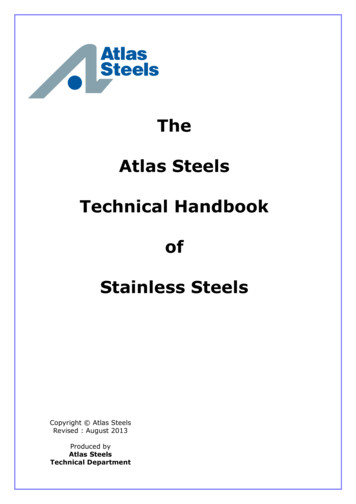
101.1 PHYSICS1.1.1 The structure of matterAll matter, be it in gaseous, liquid or solid form,is composed of atoms. Atoms are therefore thebasic building blocks of matter, though they nearlyalways appear as part of a molecule. A moleculeis a number of atoms grouped together with otheratoms of the same or a different kind. Atoms consist of a dense nucleus that is composed of protonsand neutrons surrounded by a number of small,lightweight and rapidly-spinning electrons. Otherbuilding blocks exist; however, they are not stable.All of these particles are characterized by fourproperties: their electrical charge, their rest mass,their mechanical momentum and their magneticmomentum. The number of protons in the nucleusis equal to the atom’s atomic number.The total number of protons and the number ofneutrons are approximately equal to the atom’s1:1 total mass, since electrons add nearly no mass.This information can be found on the periodicchart. The electron shell contains the same number of electrons as there are protons in the nucleus.This means that an atom is generally electricallyneutral.The Danish physicist, Niels Bohr, introduced abuild-up model of an atom in 1913. He demonstrated that atoms can only occur in a so calledstationary state and with a determined energy. Ifthe atom transforms from one energy state intoanother, a radiation quantum is emitted. This isknown as a photon.These different transitions are manifested in theform of light with different wavelengths. In aspectrograph, they appear as lines in the atom’sspectrum of lines.1.1.2 The molecule and the differentstates of matterAtoms held together by chemical bonding arecalled molecules. These are so small that 1 mm3 ofair at atmospheric pressure contains approx. 2.55 x10¹⁶ molecules.In principle, all matter can exist in four differentstates: the solid state, the liquid state, the gaseousstate and the plasma state. In the solid state, themolecules are tightly packed in a lattice structure with strong bonding. At temperatures aboveabsolute zero, some degree of molecular movement occurs. In the solid state, this is as vibrationaround a balanced position, which becomes faster1:2 neutronelectron protonThe electron shell gives elements their chemical properties. Hydrogen (top) has one electron in an electron shell.Helium (middle) has two electrons in an electron shell.Lithium (bottom) has a third electron in a second shell.A salt crystal such as common table salt NaCl has a cubicstructure. The lines represent the bonding between thesodium (red) and the chlorine (white) atoms.
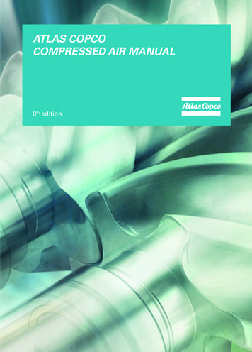
111:3Temperature C200super heatingevaporation at atmospheric pressure1000-20(steam)(water steam)ice melts(water)(ice)0100020003000kJ/kgHeat addedBy applying or removing thermal energy the physical state of a substance changes. This curve illustrates the effect forpure water.as the temperature rises. When a substance in asolid state is heated so much that the movement ofthe molecules cannot be prevented by the rigid lattice pattern, they break loose, the substance meltsand it is transformed into a liquid. If the liquid isheated further, the bonding of the molecules isentirely broken, and the liquid substance is transformed into a gaseous state, which expands in alldirections and mixes with the other gases in theroom.When gas molecules are cooled, they loose velocity and bond to each other again to produce condensation. However, if the gas molecules are heatedfurther, they are broken down into individualsub-particles and form a plasma of electrons andatomic nuclei.1 bar 1 x 10⁵ Pa. The higher you are above (orbelow) sea level, the lower (or higher) the atmospheric pressure.1.2 PHYSICAL UNITS1.2.3 Thermal capacity1.2.1 PressureThe force on a square centimeter area of an air column, which runs from sea level to the edge of theatmosphere, is about 10.13 N. Therefore, the absolute atmospheric pressure at sea level is approx.10.13 x 104 N per square meter, which is equal to10.13 x 104 Pa (Pascal, the SI unit for pressure).Expressed in another frequently used unit:1.2.2 TemperatureThe temperature of a gas is more difficult to defineclearly. Temperature is a measure of the kineticenergy in molecules. Molecules move more rapidly the higher the temperature, and movement completely ceases at a temperature of absolute zero.The Kelvin (K) scale is based on this phenomenon,but otherwise is graduated in the same manner asthe centigrade or Celsius (C) scale:T t 273.2T absolute temperature (K)t centigrade temperature (C)Heat is a form of energy, represented by the kineticenergy of the disordered molecules of a substance.The thermal capacity (also called heat capacity) ofan object refers to the quantity of heat required toproduce a unit change of temperature (1K), and isexpressed in J/K.The specific heat or specific thermal capacity of asubstance is more commonly used, and refers to thequantity of heat required to produce a unit change oftemperature (1K) in a unit mass of substance (1 kg).
121:4actual pressureeffective pressure(gauge pressure)bar (g) bar (e)absolutepressurebar (a)variable r (a)normalatmosphericpressure (a)vacuum bar (u)absolutepressurebar (a)zero pressure (perfect vacuum)Most pressure gauges register the difference between the pressure in a vessel and the local atmospheric pressure. Therefore to find the absolute pressure the value of the local atmospheric pressure must be added.1:5oC100water boils500water 0037335050absolute zero0This illustrates the relation between Celsius and Kelvinscales. For the Celsius scale 0 is set at the freezing pointof water; for the Kelvin scale 0 is set at absolute zero.Specific heat is expressed in J/(kg x K). Similarly,the molar heat capacity is dimensioned J/(mol x K).cp cV Cp CV specific heat at constant pressurespecific heat at constant volumemolar specific heat at constant pressuremolar specific heat at constant volumeThe specific heat at constant pressure is alwaysgreater than the specific heat at constant volume.The specific heat for a substance is not a constant,but rises, in general, as the temperature rises.For practical purposes, a mean value may be used.For liquids and solid substances cp cV c. To heata mass flow ( m) from temperature t1 to t2 will thenrequire:PmcT heat power (W)mass flow (kg/s)specific heat (J/kg x K)temperature (K)
13The explanation as to why cp is greater than cV isthe expansion work that the gas at a constant pressure must perform. The ratio between cp and cV iscalled the isentropic exponent or adiabatic exponent, К, and is a function of the number of atomsin the molecules of the substance.1.2.4 WorkMechanical work may be defined as the product ofa force and the distance over which the force operates on a body. Exactly as for heat, work is energythat is transferred from one body to another. Thedifference is that it is now a matter of force insteadof temperature.An illustration of this is gas in a cylinder beingcompressed by a moving piston. Compressiontakes place as a result of a force moving the piston.Energy is thereby transferred from the piston tothe enclosed gas. This energy transfer is work inthe thermodynamic sense of the word. The resultof work can have many forms, such as changes inthe potential energy, the kinetic energy or the thermal energy.The mechanical work associated with changes inthe volume of a gas mixture is one of the mostimportant processes in engineering thermodynamics. The SI unit for work is the Joule: 1 J 1Nm 1 Ws.1.2.5 PowerPower is work performed per unit of time. It is ameasure of how quickly work can be done. The SIunit for power is the Watt: 1 W 1 J/s.For example, the power or energy flow to a driveshaft on a compressor is numerically similar to theheat emitted from the system plus the heat appliedto the compressed gas.1.2.6 Volume rate of flowThe volumetric flow rate of a system is a measureof the volume of fluid flowing per unit of time.It may be calculated as the product of the crosssectional area of the flow and the average flowvelocity. The SI unit for volume rate of flow ism3/s.However, the unit liter/second (l/s) is also frequently used when referring to the volume rate offlow (also called the capacity) of a compressor. Itis either stated as Normal liter/second (Nl/s) or asfree air delivery (l/s).With Nl/s the air flow rate is recalculated to “thenormal state”, i.e. conventionally chosen as 1.013bar(a) and 0 C. The Normal unit Nl/s is primarilyused when specifying a mass flow.For free air delivery (FAD) the compressor’s output flow rate is recalculated to a free air volumerate at the standard inlet condition (inlet pressure1 bar(a) and inlet temperature 20 C). The relationbetween the two volume rates of flow is (note thatthe simplified formula below does not account forhumidity):qFAD qN TFAD T N pFAD pN Free Air Delivery (l/s)Normal volume rate of flow (Nl/s)standard inlet temperature (20 C)Normal reference temperature (0 C)standard inlet pressure (1.00 bar(a))Normal reference pressure(1.013 bar(a))1.3 THERMODYNAMICS1.3.1 Main principlesEnergy exists in various forms, such as thermal,physical, chemical, radiant (light etc.) and electrical energy. Thermodynamics is the study of thermal energy, i.e. of the ability to bring about changein a system or to do work.The first law of thermodynamics expresses theprinciple of conservation of energy. It says thatenergy can be neither created nor destroyed, andfrom this, it follows that the total energy in a closedsystem is always conserved, thereby remainingconstant and merely changing from one form into
14another. Thus, heat is a form of energy that can begenerated from or converted into work.The second law of Thermodynamics states thatthere is a tendency in nature to proceed towarda state of greater molecular disorder. Entropy isa measure of disorder: Solid crystals, the mostregularly structured form of matter, have very lowentropy values. Gases, which are more highly disorganized, have high entropy values.The potential energy of isolated energy systemsthat is available to perform work decreases withincreasing entropy. The Second Law of Thermodynamics states that heat can never of “its owneffort” transfer from a lower-temperature regionto a higher temperature region.This can be written:vp absolute pressure (Pa)v specific volume (m³/kg)T absolute temperature (K) individual gas constant J/ (kg x K)The individual gas constant R only depends on theproperties of the gas. If a mass m of the gas takesup the volume V, the relation can be written:1.3.2 Gas lawsBoyle’s law states that if the temperature is constant (isotherm), then the product of the pressureand volume are constant. The relation reads:p absolute pressure (Pa)V volume (m³)This means that if the volume is halved during compression, then the pressure is doubled, providedthat the temperature remains constant.Charles’s law says that at constant pressure (isobar), the volume of a gas changes in direct proportion to the change in temperature. The relationreads:V volume (m³)T absolute temperature (K)The general law of state for gases is a combination of Boyle’s and Charles’s laws. This states howpressure, volume and temperature will affect eachother. When one of these variables is changed, thisaffects at least one of the other two variables.pVnR T absolute pressure (Pa)volume (m³)number of molesuniversal gas constant8.314 (J/mol x K)absolute temperature (K)1.3.3 Heat transferAny temperature difference within a body orbetween different bodies or systems leads to thetransfer of heat, until a temperature equilibrium isreached. This heat transfer can take place in threedifferent ways: through conduction, convectionor radiation. In real situations, heat transfer takesplace simultaneously but not equally in all threeways.Conduction is the transfer of heat by direct contactof particles. It takes place between solid bodies orbetween thin layers of a liquid or gas. Vibratingatoms give off a part of their kinetic energy to theadjacent atoms that vibrate less.Q λ A t ΔTΔx heat transferred (J)thermal conductivity coefficient(W/m x K)heat flow area (m²)time (s) temperature difference (cold – hot) (K)distance (m)
15Convection is the transfer of heat between a hotsolid surface and the adjacent stationary or moving fluid (gas or liquid), enhanced by the mixingof one portion of the fluid with the other. It canoccur as free convection, by natural movement ina medium as a result of differences in density dueto temperature differences. It can also occur asforced convection with fluid movement caused bymechanical agents, for example a fan or a pump.Forced convection produces significantly higherheat transfer as a result of higher mixing velocities.Q h A t ΔTheat transferred (J)heat transfer coefficient (W/m² x K)contact area (m²)time (s) temperature difference (cold – hot) (K)Radiation is the transfer of heat through emptyspace. All bodies with a temperature above 0 Kemit heat by electro-magnetic radiation in alldirections. When heat rays hit a body, some of theenergy is absorbed and transformed to heat up thatbody. The rays that are not absorbed pass throughthe body or are reflected by it.In real situations, heat transmission is the sum ofthe simultaneous heat transfer through conduction,convection and radiation.Generally, the heat transmission relation belowapplies:Q k A t T total heat transmitted (J)total heat transfer coefficient (W/m² x K)area (m²)time (s)temperature difference (cold – hot) (K)Heat transfer frequently occurs between two bodiesthat are separated by a wall. The total heat transfercoefficient “k” depends on the heat transfer coefficient of both sides of the wall and on the coefficientof thermal conductivity for the wall itself.1:6This illustrates the temperature gradient in counter flow and in parallel flow heat exchangers.
16For a clean, flat wall the relation below applies:1.3.4.1 Isochoric process1:7α1 , α2 heat transfer coefficient oneach side of the wall (W/m² x K)d thickness of the wall (m)λ thermal conductivity for the wall (W/m x K)k total heat transfer coefficient (W/m² x K)The heat transmission in a heat exchanger is ateach point a function of the prevailing temperaturedifference and of the total heat transfer coefficient.It requires the use of a logarithmic mean temperature difference Өm instead of a linear arithmeticΔT.The logarithmic mean temperature difference isdefined as the relationship between the temperature differences at the heat exchanger’s two connection sides according to the expression:Өm logarithmic mean temperaturedifference (K)1.3.4 Changes in stateChanges in state for a gas can be followed fromone point to another in a p/V diagram. For reallife cases, three axes for the variables p, V and Tare required. With a change in state, we are movedalong a 3-dimensional curve on the surface in thep, V and T space.However, to simplify, we usually consider the projection of the curve in one of the three planes. Thisis usually the p/V plane. Five different changes instate can be considered:- Isochoric process (constant volume),- Isobaric process (constant pressure),- Isothermal process (constant temperature),- Isentropic process (without heat exchange withsurroundings),- Polytropic process (complete heat exchange withthe surroundings).pp2p T22q12 applied energy1p1 T1V1 V2VIsochoric change of state means that the pressure changes, while the volume is constant.Heating a gas in an enclosed container is an example of the isochoric process at constant volume.QmcVT quantity of heat (J)mass (kg)specific heat at constant volume (J/kg x K)absolute temperature (K)1.3.4.2 Isobaric process1:8pp1V1T1q 12 applied energy2V2T2VIsobaric change of state means that the volume changes,while the pressure is constant.
17Heating a gas in a cylinder with a constant load onthe piston is an example of the isobaric process atconstant pressure.1.3.4.4 Isentropic process1:10pQmcpT quantity of heat (J)mass (kg)specific heat at constant pressure (J/kg x K)absolute temperature (K)pp22isentropic1.3.4.3 Isothermal process1p11:9V2p2q quality of heat led off121p1V2V1VAn isentropic process exists if a gas is compressedin a fully-insulated cylinder without any heatexchange with the surroundings. It may also existif a gas is expanded through a nozzle so quicklythat no heat exchange with the surroundings hastime to occur.orIsothermal change of state means that the pressure andvolume are changed while the temperature remains constant.If a gas in a cylinder is compressed isothermally, aquantity of heat equal to the applied work must begradually removed. This is unpractical, as such aslow process cannot occur.p absolute pressure (Pa)V volume (m³)T absolute temperature (K)κ Cp / CV isentropic exponent1.3.4.5 Polytropic processQmRTVp VWhen the entropy in a gas being compressed or expanded is constant, no heat exchange with the surroundingstakes place. This change in state follows Poisson’s law.pp2V1quantity of heat (J)mass (kg)individual gas constant (J/kg x K)absolute temperature (K)volume (m³)absolute pressure (Pa)The isothermal process involves full heat exchangewith the surroundings and the isotropic processinvolves no heat exchange whatsoever. In reality,all processes occur somewhere in between theseextreme: the polytropic process. The relation forsuch a process is:pVnnnn constant absolute pressure (Pa) volume (m³) 0 for isobaric process 1 for isothermal process κ for isentropic process for isochoric process
181.3.5 Gas flow through a nozzleThe gas flow through a nozzle depends on thepressure ratio on the respective sides of the nozzle.If the pressure after the nozzle is lowered, the flowincreases. It only does so, however, until its pressure has reached half of the pressure before thenozzle. A further reduction of the pressure afterthe opening does not bring about an increase inflow.This is the critical pressure ratio and it is dependenton the isentropic exponent (κ) of the particular gas.The critical pressure ratio also occurs when theflow velocity is equal to the sonic velocity in thenozzle’s narrowest section.The flow becomes supercritical if the pressureafter the nozzle is reduced further, below the critical value. The relation for the flow through thenozzle is:QαψART1p1 mass flow (kg/s)nozzle coefficientflow coefficientminimum area (m²)individual gas constant (J/kg x K)absolute temperature before nozzle (K)absolute pressure before nozzle (Pa)1.3.6 Flow through pipesThe Reynolds number is a dimensionless ratiobetween inertia and friction in a flowing medium.It is defined as:in relation to each other in the proper order. Thevelocity distribution across the laminar layers isusually parabolic shaped.With Re 4000 the inertia forces dominate thebehavior of the flowing medium and the flowbecomes turbulent, with particles moving randomly across the flow. The velocity distribution acrossa layer with turbulent flow becomes diffuse.In the critical area, between Re 2000 andRe 4000, the flow conditions are undetermined,either laminar, turbulent or a mixture of the both.The conditions are governed by factors such as thesurface smoothness of the pipe or the presence ofother disturbances.To start a flow in a pipe requires a specific pressuredifference to overcome the friction in the pipe andthe couplings. The amount of the pressure difference depends on the diameter of the pipe, its lengthand form as well as the surface smoothness andReynolds number.1.3.7 ThrottlingWhen an ideal gas flows through a restrictor witha constant pressure before and after the restrictor, the temperature remains constant. However, apressure drop occurs across the restrictor, throughthe inner energy being transformed into kineticenergy. This is the reason for which the temperature falls. For real gases, this temperature changebecomes permanent, even though the energy content of the gas remains constant. This is called theJoule-Thomson effect. The temperature change isequal to the pressure change across the throttlingmultiplied by the Joule-Thomson coefficient.1:11D characteristic dimension(e.g. the pipe diameter) (m)w mean flow velocity (m/s)ρ density of the flowing medium (kg/m³)η medium dynamic viscosity (Pa . s)In principal, there are two types of flow in a pipe.With Re 2000 the viscous forces dominate inthe medium and the flow becomes l
8th edition Compressed Air Manual 8 th edition www.atlascopco.com Belgium, 2015, 9780 0380 11 CAM_cover_English_2014.indd 1 13/04/15 14:54. COMPRESSED . there will always be room for new technical improvements and better ways of doing things. Our mission at Atlas Copco is to continuously deliver superior sustainable productivity through safer .