Transcription
HVAC Control & Balancing DampersModels VCD, ICD, FBH, FBV, MBD and RBD Selection Construction PerformanceJanuary12018
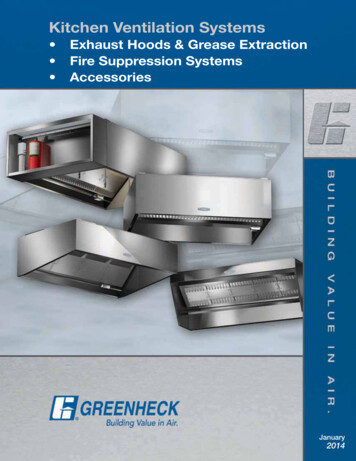
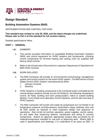
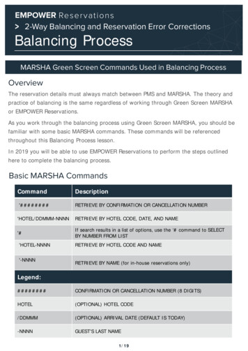
Design and ConstructionFeaturesBladeBearingShaftExtensionJamb Seal Commercial Control Dampers are used inbuildings to regulate the flow of air in anHVAC system. They can be used in intake,exhaust, or mixed air applications.There are two categories of controldampers: Balancing Volume ControlStandoffBracketAxleFrameBlade SealLinkageFrame - Tog-L-Loc AdvantageGreenheck control dampers utilize a 5 in. x 1 in. (127mm x 25mm) hat channel frame. Each frame is builtwith four separate pieces of material and joined by our Tog-L-Loc process.Rigid frame - The joint has an equivalent thickness of 10 ga. (3.5mm) steel.Increased corrosion resistance - The Tog-L-Loc process does not use heat, soGreenheck damper frames have greater corrosion resistance by retaining thegalvanized coating.Tog-L-Loc Reinforced CornerSquare frame for easier install - Using four separate frame components (top,bottom, and two sides), Greenheck’s Tog-L-Loc process results in four sturdy,90º joints. This ensures that each Greenheck damper is square and providesoptimum performance in the field.Frame OptionsThere are five frame options available: Channel (standard) - allows damper to beinsert mounted into an opening or duct Single flange or single reverse flange - canbe insert mounted or directly mountedto the wall or mating surfaces such as langeReverseplenum wall(actuator side)Flange Double flange - when you are not sure(opposite actuator)which side you need a flange Quick connect (VCD-43, -43V; ICD series) - designed to match up to a TDC, TDF, or Ductmate connectionMaximize Performance - Low Profile FrameOn dampers that are 17 in. (432mm) high or less, Greenheck uses a low profile topand bottom frame section to maximize free area which allows for lower pressuredrop and increases damper performance.2
Design and ConstructionFeatures Blades3V BladeSteel AirfoilBlade Fabricated from a singlethickness galvanized steel orstainless steel Three V-type grooves running thefull length of the blade to increasestrength Low to medium velocity andpressure applications Constructed of double-skingalvanized steel or stainless steel This blade design results inlower resistance to airflow andincreased strength High velocity and pressureapplicationsAluminum AirfoilBladeICD Blade Constructed of heavy gaugeextruded aluminum This blade design results inlower resistance to airflow andincreased strength High velocity and pressureapplications Extruded aluminum airfoil bladeswith thermal breaks and insulatedwith polyurethane foam Used in harsh environments/hightemperature differentialsVariable Symmetric Blade Design (VSB) - a Greenheck Exclusive!Airflow worksagainstactuatorAirflow rflowworks withactuatorUnbalanced BladeRequires Higher TorqueBalanced BladeRequires Less Torque Blades are symmetric about their axis Combination of 4, 5, 6, and 7 in. (102, 127, 152, and 178mm) bladewidths are used in a single damper Reduces the need for closure strips which optimize pressuredrop performances Damper can be mounted in either direction of flow Through extensive testing of our dampers, we have determined usingvarious blade sizes reduces required actuator torque which reducesthe size and quantity of actuators used on dampers. This reducesfirst costs for the building owner and on-going electrical powerconsumption.Parallel Versus Opposed Blade OperationGreenheck control dampers are offered with either parallel or opposed blades.Each style has distinguishing characteristics in regard to the type of operationrequired. Parallel blade operation - This configuration requires the damper blades torotate in the same direction, parallel to one another. Parallel blade orientationis typically used when the damper operates in two positions, open or closed. Opposed blade operation - Adjacent damper blades rotate opposite oneanother under opposed blade configuration. Opposed blade configuration istypically used on dampers that modulate airflow.ParallelBladesOpposedBladesSealsSeals are used for low leakage applications. Blade seals: Thermoplastic Elastomer (TPE) is standard. For extremetemperatures, select silicone seals. Sweep seals: Sweep seals are used on bottom of damper blades to eliminatethe use of closure strips (size dependent). Jamb seals: Jamb seals are constructed of 304SS jamb seal to help reduceleakage along the blade edges. The ICD series have silicone jamb sealsavailable for cold temperature applications.JambSeal3
Design and ConstructionFeatures LinkageGreenheck control dampers have blade linkages concealed in the frameto prevent additional pressure drop and unwanted noise. The linkage isengineered to accurately control each and every blade without need foradjustment.LinkageBearingsSynthetic - Standard on VCD series304SS - Optional, used for extreme temperatures or environment316SS - Used on SEVCD seriesICD series - Dual bearing with inner sleeve and flanged outer bearingfeatures no metal-to-metal or metal-to-plastic contactSynthetic304SSEnergy CodesThree common energy code standards that pertain to dampers are: ASHRAE Standard 90.1 - Energy Standard for Buildings except Low-Rise Residential Buildings California Title 24 IECC - International Energy Conservation CodeThe primary requirements for dampers based on each standard:ASHRAE Standard 90.1 (2013 edition) states that maximum damper leakage at 1 in. wg for a: non-motorized damper is 20 cfm/ft2 or motorized damper is 4 cfm/ft2 (see Table 6.4.3.4.3 from ASHRAE Standard 90.1)California Title 24 (2013 edition, section 140.4.4) states that the dampers shall be certified in accordancewith AMCA Publication 511 to have a maximum leakage of 10 cfm/ft2 at 1 in. wg. The dampers have beentested and are able to open and close against the rated airflow and pressure of the system after 60,000damper opening and closing cycles.IECC (2015, section C402.5.5) states that the outdoor air supply and exhaust opening be suppliedwith Class 1A motorized dampers with a maximum leakage rate of 4 cfm/ft2 at 1 in. wg when tested inaccordance with AMCA 500D.Greenheck’s volume control dampers meets the requirements of ASHRAE, California Title 24 and IECC.4
Air LeakagePerformance Air leakage is based on operation between 32 and 120 F (0 and 49 C).Tested for leakage in accordance with ANSI/AMCA Standard 500-D, Figure 5.5.Tested for air performance in accordance with ANSI/AMCA Standard 500-D, Figures 5.2, 5.3 and 5.5.TorqueData is based on a torque of 5.0 in-lb/ft² (0.56 N·m) applied to close and seat the damper during the test.VCD-23, SEVCD-23Leakage Class*MaximumDamper Width1 in. wg(0.25 kPa)4 in. wg(1 kPa)5 in. wg(1.2 kPa)48 in. (1219mm)1A11MaximumDamper Width1 in. wg(0.25 kPa)4 in. wg(1 kPa)8 in. wg(2 kPa)10 in. wg(2.5 kPa)60 in. (1524mm)1A111VCD-43Leakage Class*TorqueData is based on a torque of 7.0 in-lb/ft² (0.79 N·m) applied to close and seat the damper during the test.VCD-33, 34SEVCD-33Leakage Class*MaximumDamper Width1 in. wg(0.25 kPa)4 in. wg(1 kPa)8 in. wg(2 kPa)10 in. wg(2.5 kPa)60 in. (1524mm)1A111TorqueData is based on a torque of 9.0 in-lb/ft² (1.02 N·m) applied to close and seat the damper during the test.ICD-44, 45Leakage Class*MaximumDamper Width1 in. wg(0.25 kPa)4 in. wg(1 kPa)8 in. wg(2 kPa)10 in. wg(2.5 kPa)48 in. (1219mm)1A111*Leakage Class DefinitionsThe maximum allowable leakage is defined by AMCA as the following: Leakage Class 1A 3 cfm/ft2 @ 1 in. wg (Class 1A is only defined at 1 in. wg). Leakage Class 1 4 cfm/ft2 @ 1 in. wg8 cfm/ft2 @ 4 in. wg- 11 cfm/ft2 @ 8 in. wg- 12.6 cfm/ft2 @ 10 in. wgMaximum Leakagecfm/sq. ft. (cmh/sq.m)PressureModel@ 1 in. wg(0.25 kPa)@ 4 in. wg(1 kPa)VCD-23V, 43VClass 1AClass 1VCD-40Class 1AClass 1VCD-33, 42, 42VClass 1AClass 1VCDR-53Class 1Class 1VCDRM-53Class 1Class 15
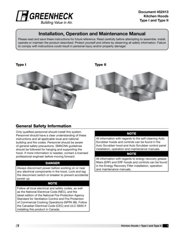
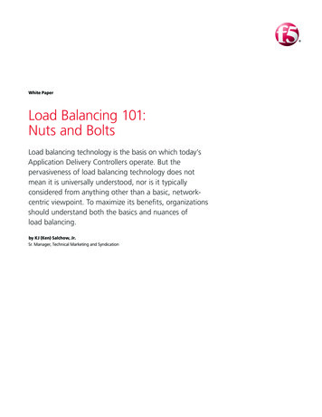
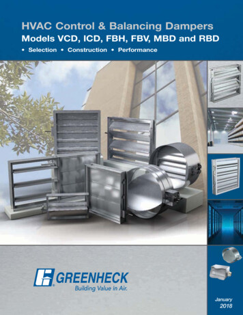
Pressure DropData Pressure Drop ComparisonGreenheck compared the AMCA licensed pressure drop data of a VCD-33 12 in. wide x 12 in. high(305mm x 305mm) versus a competitor’s equivalent 12 in. wide x 12 in. high (305mm x 305mm) damper.Both dampers were tested in a fully ducted system. The chart below shows the results at a velocity of2,000 ft./min. The results were dramatic!AMCA Licensed Pressure Drop DataPressure Drop (in. wg)10.0Competitor1.00.34 in. wgGreenheck VCD-330.10.08 in. wgAMCA Figure 5.312 in. x 12 in.Fabricated Airfoil Damper0.011,0002,00010,000Velocity (ft./min)To illustrate the cost saving benefits of a damper with lower pressure loss, we put our VCD-33 controldamper to the test. Greenheck’s VCD-33 requires 30% less energy consumption to achieve the same CFMas our competitor. Based on an energy rate of .10 kWh, continuous operation (24 hours per day, 365 daysper year) for one damper, a realized savings of 173.76 can be obtained.Revit The latest edition of ASHRAE 90.1 mandates specific fan power limits based on cfm. By usingGreenheck’s Revit models with the most accurate and lowest certified pressure loss performance in theindustry, engineers can analyze their designs to minimize system effects. Contact your local Greenheckrepresentative to calculate the actual pressure loss based on your cfm or velocity.6
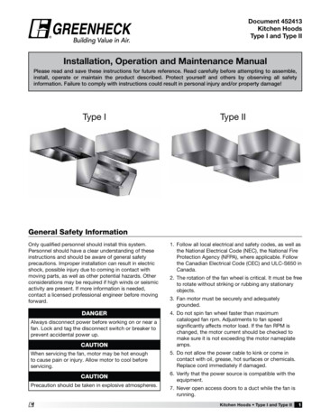
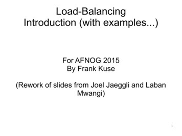
Pressure DropPerformance Pressure drop testing was conducted in accordance with AMCA Standard 500-D using the threeconfigurations shown. All data has been corrected to represent standard air at a density of3.075 lb/ft (1.2 kg/m3).Actual pressure drop found in an HVAC system is a combination of many factors. This pressure dropinformation, along with an analysis of other system influences should be used to estimate actual pressurelosses for a damper installed in an HVAC system.Figure 5.3 Illustrates a fully ducted damper. This configuration has the lowest pressure drop of the threetest configurations because entrance and exit losses are minimized by straight duct runs upstream anddownstream of the damper.Figure 5.2 Illustrates a ducted damper exhausting air into an open area. This configuration has a lowerpressure drop than Figure 5.5 because entrance losses are minimized by a straight duct run upstream ofthe damper.Figure 5.5 Illustrates a plenum mounted damper. This configuration has the highest pressure drop becauseof high entrance and exit losses due to the sudden changes of area in the system.5D6DFigure 5.35DD Duct lengthW Damper widthH Damper heightFigure 5.2Figure 5.5D 4 (W) (H)3.14Greenheck Fan Corporation certifies that themodel VCD-20 and VCD-40 shown herein arelicensed to bear the AMCA Seal. The ratingsshown are based on tests and proceduresperformed in accordance with AMCA Publication511 and comply with the requirements of theAMCA Certified Ratings Programs. The AMCACertified Ratings Seal applies to Air Performanceratings only.Greenheck Fan Corporation certifies that themodel VCD-23, 33, 34, 43, SEVCD-23 and 33shown herein are licensed to bear the AMCASeal. The ratings shown are based on tests andprocedures performed in accordance with AMCAPublication 511 and comply with the requirementsof the AMCA Certified Ratings Programs. TheAMCA Certified Ratings Seal applies to AirLeakage and Air Performance ratings.Greenheck Fan Corporation certifies that themodel ICD-44 and ICD-45 shown herein arelicensed to bear the AMCA Seal. The ratingsshown are based on tests and proceduresperformed in accordance with AMCA Publication511 and comply with the requirements of theAMCA Certified Ratings Programs. The AMCACertified Ratings Seal applies to Air Leakage, AirPerformance and Energy Efficiency ratings.7
Pressure Drop Data ICD-44 and ICD-45 Extruded aluminum airfoil blades with thermal breaks and insulated with polyurethane foam Extruded Frame (ICD-44) with thermal breaks (ICD-45)DimensioninchesAMCA t/min.)5.25.312x485.55.35.55.25.35.5Pressure Drop in. .02.432.982.301.033.70VCDR-50 and 53 Insert type round single blade Blade seals VCDR-53DimensioninchesAMCA sure Drop in. 60.23.09.563000.53.19.86.33.13.81VCDRM-50 and 53 Insert type round multi-blade Blade seals VCDRM-53DimensioninchesAMCA .3365.55.25.35.5Pressure Drop in. .181.231.58
Pressure Drop Data VCD-20, 23SEVCD-23 Galvanized 3V blade Blade and jamb seals VCD-23 316 stainless steel 3V blade 316 stainless steel construction Blade and jamb sealsDimensioninchesAMCA re Drop in. 7.392.01VCD-20V and 23V Vertical 3V blade Blade and jamb seals VCD-23VDimensioninchesAMCA re Drop in. 1000.05.03.13.03.02.
(actuator side) Single Reverse Flange (opposite actuator) Commercial Control Dampers are used in buildings to regulate the flow of air in an HVAC system. They can be used in intake, exhaust, or mixed air applications. There are two categories of control dampers: Balancing Volume Control Maximize Performance - Low Profile Frame On dampers that are 17 in. (432mm) high or less, Greenheck .