Transcription
Plant Design Using SolidWorks Together withSolution Partner Products and OtherStandard Industry ToolsDr. Vladimir Popov, CEO of SolidACE, Director, IN RE UABAndrej Jarmolajev, Technical Director, IN RE UAB
About IN RECAD/CAM/CAE/PDM Systems providerand CAD/CAE Software Developer inLithuania and Baltic‟s since 1996.DS SolidWorks VAR since 2004
About IN RE Since 1997 - SRAC (COSMOS/M) authorized representative inBaltic‟s. Since 2002 - SolidWorks reseller in Lithuania. Since 2004 authorized SolidWorks Corp representative inLithuania. 2005. IN RE staff members achieved Certified SolidWorksProfessional and Certified SolidWorks Support Technican status. 2005. IN RE signed SolidWorks Research AssociationAgreement. 2006. IN RE staff members achieved Certified COSMOS SupportTech. – Core qualification. 2006. IN RE staff members achieved SolidWorks CertifiedInstructor qualification. 2007. IN RE received Authorized Training, Testing & SupportCenter status.COSMOSWorksCertifiedSupportProviderCore
About SolidACECAD/CAE Software Developerfor SolidWorks since 2008CAD/CAM/CAE/PDM Systems providerand CAD/CAE Software Developer inLithuania and Baltic‟s since 1996.DS SolidWorks VAR since 2004Software Development Services providerfor CAD/CAM/CAE/PDM since 1999.Working for DS SolidWorks projectssince 2001
About SolidACE November 7, 2008; SolidACE, a new companydeveloping computer aided design and engineeringtools within the SolidWorks environment for theArchitectural, Building and Construction Engineering andPlant Engineering markets, was registered in Lithuania. SolidACE was created by experienced and dedicatedstructural steelwork software professionals from IN REand includes a development team in Dnepropetrovsk,Ukraine, which brings many years of SolidWorksdevelopment expertise to the team. November, 2008. SolidACE signed SolidWorks ResearchAssociation Agreement for BuiltWorks development. January, 2009. SolidACE – SolidWorks Solution Partner November 9, 2009; first commercial release ofBuiltWorks 2010 is announced January 25, 2010; BuiltWorks 2010 Release 1.1 isannounced
SOLIDWORKS IN PLANT ANDSTRUCTURAL DESIGNWORLD
Tasks for Plant Design An Industrial Plant facility is a multi disciplinary design task which includes 2D Schematic Model Design P&ID, PFD, Instrumentation, Electrical, etc. 3D plant Model Developing(Design & Analysis) Equipment Piping, Structural, Mechanical, etc. third level bullet Operation process design Construction simulation Review Maintenance & SupportTaken from Bentley Systems presentation
Plant components Equipment and Mechanical parts––––3D ModelingDrawings & B.O.M.Stress AnalysisFlow & Heat transfer Analysis Piping System Pipes, elbows, tees, reducers Instruments and control systems Supports, etc. Steel structures Building frameworks Pipeline trestles Equipment supports Service, staircases, handrails, etc.
Plant components Design of Equipment and Mechanical parts 3D Modeling Drawings & B.O.M. Stress Analysis Flow & Heat transfer Analysis Design of Piping System 3D Modeling (Routing) Drawings & B.O.M. Stress & Flow Analysis Data exchange with piping A&D systems Design of Steel structures 3D Modeling Drawings & B.O.M. Connection detailing Stress Analysis Data exchange with structural A&D systems
SOLIDWORKS FOR DESIGNOF EQUIPMENT ANDMECHANICAL PART
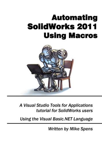
SolidWorks for Equipment modeling SolidWorks allows the application offull scale layouts and detailed designof plant equipment and it‟scomponents: Installation units and assemblies Production tools and accessories Process columns and towers Tanks and vessels Heat exchangers, boilers Piping components Pumps, valves, nozzles, fittings, Devices and instruments Supports and connections Mechanical parts and elementsARIONEX UAB, Kaunas
SolidWorks Simulation tools for equipment Analysis General FEM based Analysis of theequipment and it‟s components Stress – strain Buckling Fatigue Nonlinear Heat transfer Pressure vessels - code baseddesign ASME codes – „stresslinearing‟ Stress combinations of stressresults Flow and Heat transfer Analysis forprocess
SolidWorks Routing – part of SolidWorks Premium SolidWorks Routing - Piping Module allows pipeline routingbased on specification rules: Mixture of bends or elbows Focus on pipeline systemsand small facility design Piping assembliesfrom Design Library Auto-route segments Content per DIN, ISO,and ANSI standards Easy custom library creation Bend table for ManufacturingARIONEX UAB, Kaunas
SolidWorks future success in Plant industry Successful application of SolidWorks in Plantindustry depends not only on how effective,powerful and flexible are modeling, routing,and drawing tools, but also how theinformation created in SolidWorks andSolidWorks add-ins can be translated toCAD/CAE systems from PLANT industry. SolidWorks has really excellent kit of neutralexchange formats, but they are more typicalfor MECHANICAL (Equipment) rather then forPLANT industry generally. Let‟s take a look how SolidWorks can beintegrated with PLANT applications usingstandard PLANT exchange formats. .x t .sat .vda .iges .step.cis/2? .sdnf ?.dstv? .pcf
SOLIDWORKS IN INTEGRATEDPIPING DESIGN PROCESS
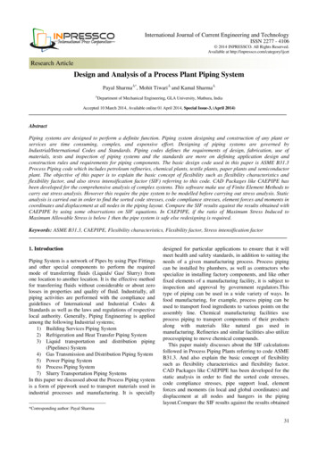
SolidWorks success in piping industry One of the key point of SolidWorkspopularity in PLANT area is thelevel of integration with PLANTindustry standard applications The is major requirement comingfrom EPC‟s and O/O‟s companiesis to establish continuous designworkflow of piping systems Modeling, Analysis, Generation ofISOGEN, Design Review Such integration level could beestablished by specific dataexchange formats which supportpiping geometry and intellectualinformation transfer through thedifferent PLANT applications
SolidWorks suscess in piping industry PCF – “de facto” industry standart forpipe exchange data. 80% of all plantdesign projects rely on Alias/Intergraphtechnology for their automated pipingisometric production (www.alias.co.uk). Using PCF file you can exchange datawith: Pipe Stress Analysis Software likeBentley AutoPIPE, CEASER II(now Intergraph!), ROHR2 andothers; Plant Design and Review Softwarelike SmartPlant 3D, PDMS,AutoPLANT, CADWorx (nowIntergraph!) and others; Piping fabrication software likeSPOOLGEN.
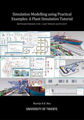
SolidWorks success in piping industryCAEReviewBOMSolidWorks RoutingAutomatedrawingPCF
What is PCF in Plant Design? PCF – Piping component file: Industry standard pipingdata exchange format Based on ISOGENstandard This is a simple text file Can be represented in 3Dusing SmartPlantIsometrics I-View,including element attributes
SolidWorks Routing PCF support To generate PCF file: Select „Export pipe/tube data‟ PCF file is stored with the SolidWorksassembly file Define CPont – connection point; Define RPoint – routing point; For many of components defineVertical axis and/or Axis ofRotation Define IsogenSkey properties More information about Isogen settingscan be learned from any ISOGENbased solutions documentation (I-Run,SmartPlant Isometrics)
SolidWorks Routing PCF support Every release of SolidWorks improves PCFsupport (for ex. SolidWorks 2010 nowsupports O-Lets), but full support of all components isnot available If you need just to transfer information tocutting machines, you have that possibility But if your task is to transfer data to pipinganalysis and other plant design systemsPCF generated by SolidWorks is notenough Using SolidWorks Routing there is noway to add miscellaneous componentslike supports, spindle directions, heat tracing,bolts, flow arrows, wall/floor symbols andetc. to ISOGEN PCF file.
Two ways to generate ISOGEN drawings of pipeline Use ALIAS I-Run to generate ISOGENdrawings Transfer piping data to I-Run for review Generate as is ISOGEN drawing
Two ways to generate ISOGEN drawings of pipeline Use ALIAS I-Run to generate ISOGENdrawings Transfer piping data to I-Run for review Generate as is ISOGEN drawing Use SmartPlant Isometrics to addadditional information and generateISOGEN drawings Transfer piping data to SmartPlantIsometrics to Add necessary information toPCF file then Generate complete ISOGENdrawing for different pipelinerepresenting style: Spool; Weld; Pipe-cut; Overview, check, etc
SolidWorks Routing PCF supportAlias eckSolidWorks RoutingSmartPlant Isometrics/SpoolgenAnalysis (AutoPIPE, CEASER II)
SOLIDWORKS IN INTEGRATEDSTRUCTURAL STEEL DESIGNPROCESS
SolidWorks application for steelwork designSteelwork for Industrial Facilities Building frameworks Pipelines trestles Equipment bearing andsupports Operating platforms Floor girders and grillages Roof structures, trusses, latticegirders, ledgers, purling Facades Wells, staircases and handrailsOKZ HOLDING Baltija UAB, Plungė
SolidWorks standart functionality SolidWorks has embedded tools forthe design of welded framestructures (Weldment) Weldment features in Part allow thecreation of frame elements (beams,columns, trusses) quickly working inthe same file. Using SolidWorks Weldment it isavailable to make detailed modeland produce design documentationfor second level structures like Pipelines small trestles Equipment bearing and supportsstructures Small maintenances platforms Staircases and handrails Trusses Containers, etc
SolidWorks standart functionality limitations All that structures are Mostly welded Not require analysis and designby Code Check requirements Working with main structures likebuildings, frameworks, operatingplatforms Weldment tools arelimited Model is more schematic ratherthan detailed (for mainequipment sitting, adjustmentvisualization) No easy way to get detaileddrawings or BOM
SolidWorks standart functionality limitations Big models of structural frameworksrequire have to be build in Assemblymode: To create big model Use multiplied elements Create connection details Generate detailed drawings and reports Link to Structural analysis and design(A&D), (not just FEA). SolidWorks Weldment can not supportsuch requirements. There are still a lot of “hand” work noautomation. Not possible to be linked to A&D Software
2 biggest SolidWorks standard functionality limitations There are two main direction to improve SolidWork productivity inStructural area1. To maintain modeling of large structures in Assembly modeworking with Weldments and other Structural Elements Add modeling capabilities for Structural Steel area in Assembly mode at thegeneral arrangement stage Add modeling capabilities for Structural Steel area at the connection detailingstage Support drawing generation conforming to Building and Structural Standards2. Integrate SolidWorks to Plant and Structural CAD/CAM/CAE/ world Aveva PDMS, Intergraph SmartPlant 3D, PDS, Bentley AutoPLANT, etc. TEKLA, ProSteel, StruCad, ProSteel, Bentley Structural, etc. Bentley STAAD.Pro, RAM Structural Systems, etc.
BuiltWorks 2010 for SolidWorks 2010 BuiltWorks is a software application for real-time steel design within the nativeSolidWorks environment, providing tools for 3D solid parametric modeling,analysis and design, connection detailing and automated generation of bothdrawings and BOMs
OKZ HOLDING Baltija UAB, PlungėBuiltWorks application areas Developed to meet the Architectural,Engineering, Construction and Plant(Process & Power) industries requirementsfor high performance flexible and versatiledesign tools Capable of maintaining an intelligent andtrue solid model-based, SolidWorks,architecture that enables the user to createan 3D real-world simulated structurecontaining all the information required forthe general and detailed design,fabrication and erection of steelworkstructures Flexible to enable external best of breedvertical market products to be linked toSolidWorks and hence creating an openenvironmentOKZ HOLDING Baltija UAB, Plungė
BuiltWorks General Concept Modeling and Detailing tools Parametric, physical 3D model of Structural framework within SW environment Connections detailing: alignment, cutting, endplates, bolted connections Structural general arrangement and detailed drawings and BOM Analysis tools SW Simulation (COSMOS) for FEM Analysis Bi-directional link to/from structural analysis package: STAAD.Pro/ SCAD Office, LIRA, Direct export/import to/from structural analysis package through STD format Integration tools Translators to other plant, structural or steel detailing and fabrication applications: SDNF, CIS/2, IFC import/export DSTV NC export
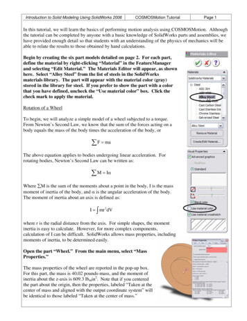
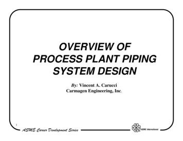
Product Philosophy7. Import/export via SDNF formats toBuilding Design Systems2. Analysis and Design3. ConnectionDetailing1. 3D Solid Parametric Modeling8. Export NC datain DSTV formats4. ConnectionsAnalysis and Design7. Import/export via SDNF formats toIndustrial Plant Design Systems6. Drawings& BOM
General Integrated workflow within SolidWorksenvironment. Common data model, common task contextmenu, intuitive user interface Native SolidWorks and embeddedBuiltWorks modelling tools to manipulatewith SolidWorks Structural elements (Weldment) inAssembly context mode BuiltWorks members (intellectual structuralobjects) both in Assembly and Part context Feature based modelling technology Model history is consistently written to aSolidWorks Feature tree which stores allinformation about structural elements anddetails, as well as their relations and attributes
Modeling BuiltWorks members areplaced, per user‟s choice, in thecontext of a parametric wireframe sketch, building grid axesor existing nodes and elementsand these are linked byassociation to the 3Drepresentation BuiltWorks has extendedInternational standard libraries ofsteel sections and materialsavailable while, in addition, theuser can create and storeelements of arbitrary shapes andparametric sections which canaccommodate for curved andtapered members.
Detailing BuiltWorks has connectionm
SolidWorks Routing –part of SolidWorks Premium SolidWorks Routing - Piping Module allows pipeline routing based on specification rules: Mixture of bends or elbows Focus on pipeline systems and small facility design Piping assemblies from Design Library Auto-route segments Content per DIN, ISO, and ANSI standards