Transcription
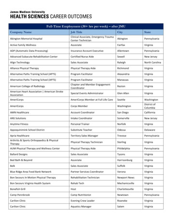
Surface DrawingSteven Schkolne Peter Schröder†Caltech Department of Computer ScienceTechnical Report CS-TR-99-03Figure 1: A guitar is Surface Drawn by forming its shape with the hand.Abstract1We present Surface Drawing, a medium which provides direct control over the creation of a wide range of intricate shapes. Surface Drawing addresses several key issues in creative expressionand perceptual thinking by providing a direct link between the motions of the hand and the forging of shapes. Surfaces are created bymoving a hand, instrumented with a special glove, through spacein a semi-immersive 3D display and interaction environment (theResponsive Workbench). This technique allows both novices andexperts to create intricate forms without the perceptual constraintsof a rigid mathematical structure, large toolset, or a reduction ofmodeling to editing. In Surface Drawing the design space can befreely explored during the modeling process without the need toplan the construction of the final shape. In particular it supports unconstrained erasing and buildup of new geometry. This is achievedthrough the use of a novel incremental construction method for triangulated meshes, the Cookie Cutter algorithm. It allows the userto freely grow, join, and erase surfaces based on hand motions. Wereport on our experiences with the system and present results created by artists and designers exploring problems in industrial design, character design, and fine art.The state of the art in three-dimensional modeling can representa variety of complex smooth surfaces. When artists and designers create shapes with these techniques, we observe that often themethod of surface representation restricts the ways in which a shapecan be modeled. Consider traditional spline-based modeling [8].While splines can represent many different shapes, a user often hasto think of the most efficient way to represent a shape before beginning the modeling process. Changing directions midway throughthe design process often requires such a drastic change in the underlying placement of patches that the user must return to the drawingboard, essentially starting from scratch [9].The traditional shape modeling approach of the graphics andCAGD communities is fundamentally different from the approachtaken by the artistic community. Consider the perhaps simplestof all modeling tools: the pencil. It is an extraordinarily effective conduit for artistic expression. Part of the reason for this isits simplicity. Another reason for its success is the close relationbetween an artist’s perception and action and the forms the pencilproduces. This link yields direct control over all aspects of form.Surface Drawing, which we introduce, provides direct control overthree-dimensional space in the same way a pencil commands twodimensional space.The key to Surface Drawing is the use of motions of the human ss@cs.caltech.edu† ps@cs.caltech.eduIntroduction
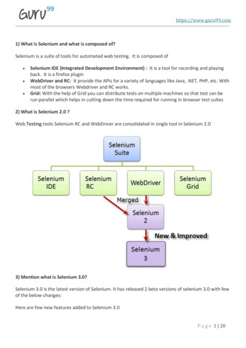
hand to describe shapes, as in Figures 1 and 4. As the hand is movedin a semi-immersive environment, a surface is grown by adding theshape of the hand at each sampling interval. The versatility andnatural understanding of the hand, combined with the simplicityof this process, allows for an intuitive modeling process in whichthe user can think perceptually about a shape while constructing it.While the resulting surface might not meet certain analytic criteria,such as curvature continuity, forms can be constructed with gestural, emotive qualities that are difficult to achieve with traditionalsurface modeling tools. This system has both the ease of use thatnovices expect and the control that experts demand. We emphasizethat the goal of our work is the creation of tools which support conceptual design and the artistic process. These methods are distinctfrom those focusing on exact specification of geometry, as neededin traditional CAD.To better understand why Surface Drawing works, we introducethe concept of perceptual thinking. This idea describes how thoughtand interface are intimately related. By reducing the distance between the actions of the modeling system and the perceptions andactions of a user, the cognitive overhead of a modeling system isgreatly reduced, freeing up resources to think about the form beingcreated.We represent our surfaces as meshes, and develop the CookieCutter algorithm for incrementally constructing a surface as it isbeing created.Our principal contributions are (a) the formulation of the principle of perceptual thinking, (b) the Surface Drawing method, whichleverages perceptual thinking, and (c) the Cookie Cutter incremental surface construction algorithm which we use in our implementation of the Surface Drawing method. These topics are presentedas follows: Section 2: Understanding modeling through perceptual thinking. Specific guidelines for creative perceptual thinking are presented. Previous work is evaluated using these guidelines. Section 3: The Surface Drawing paradigm is described in detail. Section 4: The Cookie Cutter algorithm, an interactive incremental surface construction technique, is presented. Section 5: Description of the ways in which the hand is sampledand the tools we provide for modeling. Section 6: Applications of Surface Drawing to industrial design, character design, and fine art are presented. Section 7: We discuss the benefits and shortcomings of thepresent work. Future areas of research are proposed.2Perceptual ThinkingIn his seminal text Visual Thinking [4], Arnheim describes the importance of perception in our thought processes:The cognitive operations called thinking are not the privilege of mental processes above and beyond perception,but the essential ingredients of perception itself.Arnheim finds vision to be the most important of the senses, andshows how thinking through images pervades society. McKim [17]applies the concept of visual thinking to the problem-solving process. He cites the difficulties of materials and techniques that drawattention away from the thinking process, and the need for directinteraction to support rapid ideation.Visual thinking can be expanded to include all of the senses (including proprioception) in what we call perceptual thinking. Perceptual thinking is a process in which understanding is achievedthrough direct perception, without being translated into a higherlinguistic or mathematical form. In a problem solving environment,application of perceptual thinking minimizes the distance betweenperception and the artifact being created.Consider the example of describing a set of points on a twodimensional grid for later display. A weak perceptual interface forthis task would be to write down coordinates for these points orenter them with a keyboard, only allowing the user to see themafter the input is complete. A strong perceptual interface would beto draw the points on a piece of paper, or allow the user to enterthem with a touch-sensitive computer display. The latter form ofinteraction gives the user a much stronger aesthetic control over thepoints being described.Applying these principles, we develop the following guidelinesfor an interactive modeling system:Invisible mathematical structure The behavior of the modeling system should be based upon simple physical interactions thatare understood via direct perception. The user should think primarily in terms of the model being created, instead of a structure thatmust be created to support that model. Any mathematical structurethat exists must support arbitrary changes in the model in a way thatis transparent to the user.Direct primitives Presenting an artist with a series of complexprimitives (sphere, cube, cone, etc.) forces thought in terms of theseprimitives. Unless the solution space inherently consists of theseprimitives (packing oranges or stacking bricks) they will only takethe user a step away from the form of a model. Primitives shouldbe the essential constituent parts of the modeling space.Full dimension The interface should make it easy for the userto observe the object being modeled in the number of dimensionsit has. The modeling tool should have easy control over all of itsdegrees of freedom.Small toolset The modeling operations should consist of a fewtools. If the number of such tools is large, thought must be used todecide which tool to use, instead of contemplating the object beingmodeled.Figure 2: Perceptual interaction with a surface in the semiimmersive environment of the Responsive Workbench.Direct creation Requiring an artist to create a simple object andthen edit it repeatedly to get the shape they desire forces many unnecessary intermediate perceptions which have little to do with thefinal product. We seek tools that are capable of sophisticated creation during the early stages of design.
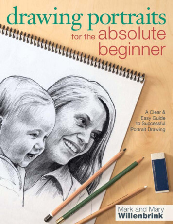
Sensory completeness The visual, haptic, and other sensesshould be used to better understand the model being created.2.1 Consider the PencilTo better understand what a perceptual, creative computer modeling tool might be, consider an exemplary traditional tool: the pencil.The movements of the hand across the page are closely tied to theresulting lines that are displayed. This single tool can be used tomake a range of shapes, from simple to intricate. The pencil doesnot require the user to work within a mathematical structure. Thepencil does not force images to be understood through primitivesthat are not related to the drawing task. The pencil allows highlycomplex shapes to be directly created without tedious editing. Thepencil allows the creation and viewing of drawings in their full dimension. Users are presented with direct control over the lines theyare making, and nothing more. The pencil is successful becauseit allows users to think perceptually about a drawing as it is beingconstructed.Even when presented with sophisticated modeling tools, artistsoften use pencils to think about models before specifying them withsoftware. This process forces a three-dimensional problem to bethought about in two dimensions. Since the object being created isthree-dimensional, this thought process would ideally take place inthree dimensions. We present such a solution in this paper.2.2 Related WorkModeling is one of the oldest problems in computer graphics [22].Most successful commercial systems for three-dimensional modeling are based on the use of tensor-product spline surfaces [8].These surfaces have nice curvature properties, but unfortunatelyrequire a very complex toolsuite for effective manipulation [2].Such techniques force artists to think in terms of mathematicalstructures which they often find counterintuitive. Once such complex systems are in place, it is difficult to make changes to partsof a model without restructuring. Current interfaces for splinebased modelers are typically based around two-dimensional viewsand two-dimensional input via a mouse. Consequently, the threedimensional structure of the product being created is not an inherentpart of the modeling process.Another well-studied modeling technique is the use of deformations. Global deformations, introduced by Barr [5], apply functions to deform space, and carry an underlying surface with them.Local deformations, such as the free-form deformations developedby Sederberg and Parry [21] allow users to make small, detailedchanges to an object. These techniques are limited because theyrequire users to start with simple shapes and work them into morecomplex forms. The sequence of changes is dictated by the underlying mathematics and is not an inherent part of the final form.Alternative methods of surface representation, such as Grimm’smanifold work [11], and Szeliski and Tonneson’s oriented particlesparadigm [23] are promising in their ability to represent a greatvariety of shapes, but their interactive potential for intricate shapeshas not been demonstrated.Some recent work has focused on different methods of interaction to solve some of the above problems. Zeleznik’s SKETCHparadigm [27] utilizes two-dimensional gestural input to describeand place objects in three-dimensional space. While SKETCHmakes efficient use of a two-dimensional input device, many of itscomplicated gesture sequences would not be necessary if the userhad a three-dimensional interface. SKETCH allows users to workprimarily in three orthogonal directions. While this is useful for thecreation of many manufactured parts, SKETCH does not immediately extend to intricate organic forms.Two-dimensional input is used to create three-dimensional figures in the work of Han [13] and van Overveld [25]. These visionbased techniques try to infer three-dimensional structure from a series of two-dimensional motions, requiring the user to think in twodimensions about a problem that is inherently three-dimensional.They do however provide means to leverage traditional drawing expertise.The HoloSketch work of Deering [6] and the 3-Draw system ofSachs et al. [19] allow users to work in three-dimensional space,but they allow only the placement of lines and, in Deering’s case,primitives such as transformed spheres. These approaches workwell for models that are made of theses primitives but do not readilyextend to the larger class of all surfaces.Finally, volume sculpting, as presented by Galyean [10] andWang [26] comes closest to meeting our guidelines. Their techniques are limited by the choice of initial volume which must contain the finished shape. Shapes must be formed by repeated subtraction steps which are somewhat indirect. In Surface Drawing weinstead opt for an additive process, providing for the direct creationof intricate geometry.Figure 3: An artist drawing a figure holds a pencil so that the regionof contact between the pencil and paper is a line.3Surface DrawingThe goal of the Surface Drawing approach is to extend the traditional system of drawing lines with a pencil to the creation offreeform surfaces. As discussed in Section 2.1 the pencil is an excellent tool for perceptual thinking. The key to understanding apencil is to analyze the way in which it is used by experts. Figure 3shows how a trained artist holds a pencil. Note that the contact between the pencil and the paper (two-dimensional space) is in theform of a line. Surface Drawing is an extension of this metaphorwhere the contact between the user and three-dimensional spaceis a plane. There is an interesting connection between this viewof drawing and manifold theory (see [1]). Drawing with a pencilis much like adding locally one-dimensional coordinate patches toa one-manifold. Modeling surfaces is the process of making twomanifolds, and Surface Drawing does this via the natural extensionof adding two-dimensional coordinate patches. In short, we viewdrawing as the development of a manifold with codimension one.We can summarize our paradigm with the following definition:Surface Drawing: A method for creating shape in which surfaces are created by moving a locally two-dimensional objectthrough three-dimensional space.A locally two-dimensional object that is very versatile and intimately entwined with human perception is the inside surface of thehand. Our implementation of Surface Drawing uses the motion ofthe hand to define portions of surfaces (see Figure 4). Notice thatthe hand is moving in the tangent plane of the surface being created,much as a pencil moves in the tangent line of a curve drawing. Afew hand motions can be combined rapidly to form a much moreelaborate surface, such as the guitar depicted in Figure 1.To realize these ideas, we need an interactive environmentwhich supports the sensing of an oriented plane at a point inthree-dimensional space. The traditional mouse/monitor interface
Figure 4: A simple drawing motion produces a small surface patch.scheme would not be fully dimensional. A system which does support five degrees of freedom on input and three-dimensional viewing of objects is the Responsive Workbench [15, 14] (see Figure 2).Its horizontal top surface (measuring 1.8 x 1.35 m) displays alternating left/right stereo images which are viewed through magnetically tracked shutter glasses. The position and orientation of the interface tools (stylus and glove) are also sensed with magnetic trackers. The hand configuration is sensed with a CyberGlove.In this fully dimensional environment, there is a perceptual connection between the form of the hand as it moves through space andthe surface that is generated. This perceptual creation, along withthe perceptual viewing of the model, allows shapes to be understoodat a deep level while they are created.Figure 6: An overview of the Cookie Cutter algorithm. A surfacepatch (shaded) near the new sample is identified. Then it is (a)projected onto R2 , (b) retriangulated, and (c) moved back to theoriginal mesh.Cutter technique avoids this overhead by retriangulating in two dimensions. An overview of the construction process is shown inFigure 6. To add a new sample to the mesh, the affected surfaceneighborhood is removed and retriangulated, taking the new datainto account. By adding the notion of orientability to our system,this algorithm also allows self-intersecting surfaces of high curvature to be formed.The following section describes this process in detail.4.1 The Cookie Cutter AlgorithmFigure 5: In the primary drawing mode, we sample position andorientation at five locations along the index finger and palm.4Surface ConstructionData from the tracker and glove is used to create a mesh of trianglesthat describes the surface being drawn. From the user’s perspective,the hand is acting as a guide for a plane. To construct a surfaceefficiently, we view the hand as a group of samples consisting ofposition and orientation (see Figure 5 for a depiction of the sampleswe use). Placing these samples as points in three space withoutconnecting them does not give a strong sense of the underlying surface being formed. We present a method, which we call the CookieCutter algorithm, that incrementally constructs a surface from thesesamples.This problem is similar to the well-studied surface reconstruction problem (for a review see [18]). Three key differences existbetween the traditional reconstruction setting and ours: Input Data: normal vectors, in addition to positions, are given; Locality: since the sample points are added interactively, globalinformation about the sample set cannot be used; Speed: the construction must be performed within tight delayand update limits to sustain the illusion of virtual reality.Approaches to reconstruction that use three-dimensional triangulation such as Edelsbrunner’s alpha shapes [7] and Amenta’s crustalgorithm [3] suffer from high computational costs. The CookieThe incremental Cookie Cutter algorithm takes an existing mesh ofsamples, edges, and triangles, M (S, E, T ), and changes it toreflect the addition of a new sample x. A sample is a position inR3 and a corresponding unit normal vector (direction), which wewrite x (xp , xd ). After receiving x, the Cookie Cutter algorithmperforms the following seven steps:1. Find neighborhood: identify a neighborhood of samples,Ns (x) S to which the new sample x should be added;2. Find surface region: the triangles Nt (x) T that correspond to this neighborhood, along with a number of boundary edges Ne (x) E describing the boundary of the surfaceregion being removed are identified;3. Ensuring non-degenerate projection: if any of the trianglesNt (x) will be flipped upon projection into the plane definedby xd , the neighborhood Ns (x) is reduced, and Nt (x) as wellas Ne (x) are updated;4. Cut: the triangles Nt (x) are removed from the mesh;5. Project: each sample in Ns (x) and each boundary edge inNe (x) are projected into the plane defined by xd ;6. Triangulate: the projection of Ns (x) is triangulated using atwo-dimensional Delaunay triangulation with some modifications;7. Unproject: each resulting Delaunay triangle is mapped backto R3 by the implicit association through Ns (x).Each of these seven steps is now described in detail.
Figure 7: A neighborhood (circled points) is taken around a newsample (in square). Using a simple dot product test, neighborhoodson (a) surfaces with high curvature and (b) intersecting or almosttouching surfaces can be formed correctly.Find neighborhood Given a new sample x, its sample neighborhood Ns (x) consists of all samples si that satisfy the followingtwo conditions:"xp sip " dmax and xd · sid cos(θmax )where " ·" is the standard Euclidean metric. Samples satisfyingthese conditions are shown as heavy dots in the example of Figure 8. In practice, we found dmax 5cm and θmax 60o towork well. These conditions choose a neighborhood that is near thenew sample both in terms of position and orientation. As shown inFigure 7, this mixed distance/orientation criterion allows us to dealeffectively with regions of high curvature or multiple surfaces intersecting. We can also handle surface parts with opposite orientationsthat are arbitrarily close to one another.Find surface region The triangle neighborhood Nt (x) consists of triangles whose vertices are all in Ns (x). Nt (x) (shadedin Figure 8) represent the set of triangles that might be changedwhen Ns (x) is retriangulated. While finding Nt (x), an array ofsigned edges, which we call boundary edges (denoted Ne (x)), isfilled with edges of triangles that contain only two points in Ns (x).Boundary edges are represented as arrows in Figure 8 (a). A boundary edge is a segment of the boundary between the surface neighborhood of x and the remainder of M , and the set of boundaryedges around a given sample forms our cookie cutter. We orienteach boundary edge using the third vertex of the triangle that wasfound to contain only two neighborhood samples. This orientationis used to prune triangles formed outside of the boundary in theretriangulation process and to ensure a non-degenerate projection.Ensure non-degenerate projection In cases of high curvature and sample noise, projection onto the tangent plane of x canflip triangles (see Figure 9). In practice, this situation occurs quiterarely. However, when it does happen, it causes a hole in our mesh.We check for this problem by storing an orientation tid for each triangle in T . Each triangle normal tid is chosen using the orientationof M . If tid · xd 0 for any triangle in T , dmax is reduced andNs (x), Nt (x), and Ne (x) are recomputed.Figure 8: A portion of the mesh is cut out and replaced by a meshregion that contains the new sample. (a) After the addition of a newsample, the samples in the neighborhood (heavy dots) and boundary edges (with arrows) are identified. The triangles in the neighborhood Nt (x) (shaded) are removed. (b) The sample neighborhood is retriangulated. (c) Triangles (shaded) that are neither onthe wrong side of a boundary edge, nor have large circumcircle, areidentified. (d) The identified triangles are added to the mesh.failure is dealt with by changing the orientation of the associatedboundary edge to ensure correct behavior.Triangulate Figure 8 (b) shows an example of a two-dimensional Delaunay triangulation [16, 12]. Note that it may contain triangles that are outside of a boundary edge (see Figure 8 (c)). Theseare removed to preserve the cookie cutter outline of the neighborhood that was originally removed from the mesh. After this cleanupthe triangles are ready to be reinserted into the original mesh (seeFigure 8 (d)). A problem with traditional Delaunay triangulations isCut The cutting step removes the triangles in Nt (x) from themesh M .Project After correctly calculating a neighborhood, the local surface region (cookie) is ready for retriangulation. Basis vectors onthe tangent plane of x are chosen, and each point in Ns (x) is givencoordinates in terms of these vectors. The edges Ne (x) that definethe boundary are also projected onto the tangent plane at x. The orientation of any boundary edge ei Ne (x) can flip upon projection,in a fashion similar to that of a triangle flipping. A dot product testsimilar to that for triangles is performed. However, this time testFigure 9: In this cross-section of a mesh, the triangle containing pand q is flipped when it is projected onto the tangent plane of thenew sample x
that the resulting triangulation is always convex. Users often makeplanar regions with concave boundaries which should be reflectedin the mesh. Removing triangles (such as the triangle in the lowerright-hand corner of Figure 8 (c)) whose associated circumcircleshave prohibitively large radii (in practice we used 2.5cm) allowsthe boundaries of meshes to be concave.Unproject The vertices of triangles in the retriangulation are allassociated with samples in the original mesh through the tangentplane projection. We map each of these samples back to their original locations in R3 , moving the new triangulation into the threedimensional space in which the user is working.4.2 DiscussionThe key elements of the Cookie Cutter approach are sample neighborhood construction and boundary computation. Using orientation information to prune the Euclidean neighborhood allows planar subsets to be found in many difficult regions, such as neighborhoods with intersecting or almost-touching surfaces. Storing aboundary allows a very efficient local retriangulation process. TheDelaunay triangulation is O(n log n) with a typically small n. Theother steps are all O(n) with the same small n. The constructionof the sample neighborhood Ns (x) is optimized with a regular gridspatial data structure.Unlike the surface reconstruction setting, where the data can beassumed to come from a clean surface, the Cookie Cutter algorithmhas to deal with “messy” samples. This is due to the inherent noisein the tracking system and the unsteadiness of users’ hands in thisenvironment. While the triangulation algorithm is provably correctin two dimensions (see [20]), this proof does not extend to the threedimensional case. Despite these issues, the algorithm manages toform clean surfaces the majority of the time. Holes and nonmanifold topology occur about one percent of the time (one bad vertexper 100 vertices). While these situations can be easily fixed by auser, automatic mending will be treated in future research. Noisealso causes the meshes to be quite bumpy at times. Thus, we applya simple Laplacian mesh smoother [24] as a post-process.finger and the palm of the inside surface of the hand (see Figure 5).Normals are taken as the normals of the outer surface of the hand.The user moves the hand as if running it across the object being created, in a direction perpendicular to the plane along which the fingerbends (see Figure 4). This allows the description of surfaces with aconsiderable range of curvature. With this system, drawing can beeasily started and stopped by pressing the thumb against the indexfinger (see Figure 10 (a)). Since the elastic tension in the CyberGlove naturally holds the thumb in the “off” position, users rarelydraw accidentally. We find that users learn this on/off mechanismquite readily.Eraser Users often want to correct or remove regions of a surface. Rather than introducing complex editing semantics, we provide the user with only a simple spherical eraser tool. It is movedthrough space, deleting geometry in its wake. We remove all thesamples and their associated triangles that are within the sphere ofthe eraser. The user switches from draw mode to erase mode bybending the metacarpophalangeal joints on the 4th and 5th fingerswhile keeping the other fingers straight (see Figure 10 (b)). Erasingis also activated pressing the thumb against the index finger. Sincegeometry can be added with ease, this simple means of editing issufficient.Manipulation The user frequently needs to work on the modelfrom different views, requiring the ability to translate and rotate. Ina 3D semi-immersive environment it is quite natural to accomplishthis with a virtual stick which can be “poked” into the object. Theobject then follows the position and orientation of the stick, providing a direct manipulation ability. In our implementation this wasaccomplished by providing a tracked stylus, which the user holdsin the subdominant hand while creating geometry with the dominant hand.Detail input Users often want to add small details to their models. Our current system allows users to add small pieces of surfacewith the tip of the index finger. This mode is accessed by bendingthe 3rd, 4th, and 5th fingers while keeping the index finger straight(see Figure 10(c)). We sample the hand as before but only use thesamples from the distal phalanx.5.1 DiscussionFigure 10: Three hand positions are identified: (a) the user drawswith the index finger and palm; (b) an eraser is placed at the endof the index and middle fingers; (c) fine details are added with thetip of the finger. In all three situations, the thumb is used to activateand deactivate the operation.In our experiments we found that this interface was learned quitereadily. One of the nice features of this system is that there is nostored interface state. The hand configuration affects how the drawing happens, and the user is never asked to perform a mode switching action requiring a movement away from the object. The manipulation task, which does not require high precision, is assignedto the subdominant hand. Moving geometry is necessary for bothdrawing and erasing, and this two-handed interface ensures that thestick is always accessible.65ImplementationThe interface to our Surface Drawing implementation consists oftwo methods for adding geometry, an eraser to remove geometry,and a simple manipulation tool. The three tools that affect geometryare accessed with three hand configurations (see Figure 10). Themanipulation tool is assigned to a magnetically tracked stylus.Primary input The choice of hand samples is important in allowing geometry to be placed effectively. We sample the indexResultsThe prototype sy
Two-dimensional input is used to create three-dimensional fig-ures in the work of Han [13] and van Overveld [25]. These vision-based techniques try to infer three-dimensional structure from a se-ries of two-dimensional motions, requiring the user to think in two dimensions about a problem that is inhere
![[ OPTIONAL ] CASE COLLATOR · 90667 LM3231 COMPLETE .](/img/4/91ga8yoa-ts.jpg)